Gas holder
A gas holder, or gasometer, is a large container in which natural gas or town gas is stored near atmospheric pressure at ambient temperatures. The volume of the container follows the quantity of stored gas, with pressure coming from the weight of a movable cap. Typical volumes for large gas holders are about 50,000 cubic metres (1,800,000 cu ft), with 60 metres (200 ft) diameter structures.

Gas holders now tend to be used for balancing purposes, to ensure gas pipes can be operated within a safe range of pressures, rather than for actually storing gas for later use.
Etymology
Antoine Lavoisier devised the gazomètre to assist his work in pneumatic chemistry.[1] These enabled him to weigh the gas in a pneumatic trough with the precision he required. He published his Traité Élémentaire de Chimie in 1789.
James Watt Junior had collaborated with Thomas Beddoes in constructing the pneumatic apparatus, a shortlived piece of medical equipment that incorporated a gazomètre. He then adapted the gazomètre for coal gas storage.[2] The anglicisation gasometer was adopted by William Murdoch, the inventor of gas lighting, in 1782, as the name for his gas holders.[3][4]
Despite the objections of Murdoch's associates that his so-called "gasometer" was not a meter but a container, the name was retained and came into general use. The term "gasometer" is discouraged for use in technical circles, where the term "gas holder" is preferred.[5] The British Ordnance Survey have marked gas holders on their large-scale maps, calling them gasometers. This term became used to label gas works, where there usually are several gas holders.
The spelling "gas holder" is used by the BBC, though the variant "gasholder" is commonly used by other publishers. The meter used to measure the flow of gas through a particular pipe is a gas meter.
History
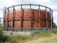
Before the mid-20th century, coal gas was produced in retorts by heating coal in the absence of air, the process being known as coal gasification. The coal gas was first used for municipal lighting, with the gas being passed through wooden or metal pipes from the retort to the lantern. The first public piped gas supply was to thirteen gas lamps installed along the length of Pall Mall, London, in 1807. The credit for this goes to the German inventor and entrepreneur Fredrick Winsor. Digging up streets to lay pipes required legislation, and this delayed the roll-out of street lighting and the installation of gas for domestic illumination, heating, and cooking.
Many people had experimented with coal distillation to produce a flammable gas. For instance Jean Tardin (1618), Clayton (1684) Jean-Pierre Minckelers, Leuven (1785) and Pickel (D)(1786). William Murdoch was successful. He had joined Boulton and Watt, at the Soho manufactory in Birmingham in 1777, and in 1792 he built a retort to heat coal to produce gas that illuminated his home and office in Redruth. The system, however, lacked a storage method. James Watt Junior adapted a Lavoisier gazomètre for this purpose. A gasometer was incorporated into the first small gasworks built for the Soho manufactory in 1798.[6]
William Murdoch and his pupil Samuel Clegg installed retorts in individual factories and work places. The earliest example was in 1805, at Lee and Phillips, Salford Twist Mill, where eight gas holders were installed.[7] This was shortly followed by one in Sowerby Bridge, constructed by Clegg for Henry Lodge. The first independent commercial gas works was built by the London and Westminster Gas Light and Coke Company in Great Peter Street, Westminster, in 1812, laying wooden pipes to illuminate Westminster Bridge with gas lights on New Year's Eve in 1813. Public gas lights were seen as a crime reduction measure, and as such, and until the 1840s, regulation lay with the police authority rather than the elected council.[8]
Safety concerns expressed by the Royal Society limited the size of gas holders to 6,000 cubic feet (170 m3) and saw them being enclosed in gasometer houses. This concern proved unfounded, and any small leak from an enclosed gas holder created a potentially explosive buildup of air and gas within the building, a far greater danger, and the practice discontinued. In the United States, however, where the gas needed to be protected from extreme weather, gasometer houses continued to be built and were architecturally decorative.[9]
By the 1850s, every small to medium-sized town and city had a gas plant to provide for street lighting. Private customers could also have piped lines to their houses. By this era, gas lighting became accepted. The advent of incandescent gas lighting in factories, homes and in the streets, replacing oil lamps and candles with steady clear light, almost matching daylight in its colour, turned night into day for many—making night shift work possible in industries where light was all important—in spinning, weaving, and making up garments, etc. Gas works were built in almost every town; main streets were brightly illuminated and gas was piped in the streets to the majority of urban households.
The telescopic gas holder was first invented as early as 1824. The cup and dip (grip) seal was patented by Hutchinson in 1833, and the first working example was built in Leeds. The benefits of the greatly increased storage the holders provided for local gas works were quickly appreciated, and gas holders were built all around the country in great numbers from the middle of the century. The first were the two-lift, column supported type; later they could have four lifts, being frame-guided, and be retrofitted with an additional flying lift. The large gas holders at King's Cross were built in the 1860s to provide gas storage for a large part of London.[10]
William Gadd of Gadd & Mason, from Manchester, invented the spirally-guided gas holder in 1890. Instead of the use of external columns or guide frames, his design operated with spiral rails. The first commercial design was built in Northwich, Cheshire, in the same year. By the end of the century, most towns in Britain had their own gas works and gas holders.[10]
The inter-war years were marked by the development of improvements in storage, especially the waterless gas holder, and in distribution, with the advent of 2-to-4-inch (50 to 100 mm) steel pipes to convey gas at up to 50 psi (340 kPa) as feeder mains to the traditional cast-iron pipes. Municipal gas works became superfluous in the latter 20th century, but gas holders and production plant were still in use in steel works in 2016.
Function
A gas holder provided storage for the purified, metered gas. It acted as a buffer, removing the need for continuous gas production. The weight of the gas holder lift (cap) controlled the pressure of the gas in the mains, and provided back pressure for the gas-making plant.
Gas holders hold a large advantage over other methods of storage. They are the only storage method which keeps the gas at district pressure (the pressure required in local gas mains). Once the district low pressure switch falls, and the booster fans come on, the gas in these holders can be at homes, being used, in a very short period of time. Gas is stored in the holder throughout the day, when little gas is being used. At about 5 pm there is a great demand for gas, and the holder will come down, supplying the service area.
However, where the distribution system is robust and contains regulators, the gas holder advantages are made redundant.
Types
There are two basic types of gas holder: the water-sealed and the rigid waterless.
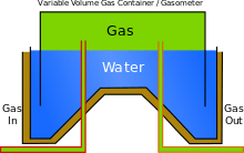
The water-sealed gas holder consists of a tank of water that rises and falls to take the gas. A watered gas holder consisted of two parts: a deep tank of water used to provide a seal, and a closed vessel (the lift) that rises above the water as the gas volume increased.[11]
Rigid waterless gas holders were a very early design that neither expanded or contracted. There are modern versions of the waterless gas holder, e.g. oil-sealed, grease-sealed and "dry seal" (membrane) types. They consist of a fixed cylinder capped by a moving piston.[12]
Water-sealed gas holders

The earliest Boulton and Watt gas holders had a single lift. The tank was above ground and was lined with wood; the lift was guided by tripods and cables. Pulleys and weights were supplied to regulate the gas pressure.[13] Brick tanks were introduced in 1818, when a gas holder would have a capacity of 20,000 cubic feet (570 m3). The engineer John Malam devised a tank with a central rod-and-tube guide system.
Telescoping holders fall into two subcategories. The earlier of the telescoping variety were column-guided variations and were built from 1824. To guide the telescoping walls, or "lifts", they have an external fixed frame, visible at a fixed height at all times. A refinement was the guide frame gas holder, where the heavy columns were replaced by a lighter and more extensive framework. Vertical girders (standards) were intersected by horizontal girders and cross-braced. This could be bolted onto an underground or above-ground tank. The Cutler patented guide frame dispensed with the horizontal girders using diagonal triangulated framing instead.[14] Cable-guided gas holders, invented by Pease in 1880, had a limited use, but were useful on unstable ground where the rigid systems could buckle and jam the lift.[14]
Spiral-guided gas holders were built in the UK from 1890 until 1983. These have no frame, and each lift is guided by the one below, rotating as it goes up as dictated by helical runners.[15]
Both telescoping types use the manometric property of water to provide a seal. The whole tank floats in a circular or annular water reservoir, held up by the roughly constant pressure of a varying volume of gas, the pressure determined by the weight of the structure, and the water providing the seal for the gas within the moving walls. Besides storing the gas, the tank's design serves to establish the pressure of the gas system. With telescoping (multiple-lift) tanks, the innermost tank has an approximately 1 ft × 2 ft (30 cm × 61 cm) lip around the outside of the bottom edge, called a cup, which picks up water as it rises above the reservoir water level. This immediately engages a downward lip on the inner rim of the next outer lift, called a dip or grip, and as this grip sinks into the cup, it preserves the water seal as the inner tank continues to rise until the grip grounds on the cup, whereupon further injection of gas will start to raise that lift as well. Holders were built with as many as four lifts.[16] An extra flying lift could be retrofitted into column or frame gas holders. This was an additional inner tank that extended above the standards, when the infrastructure would support the extra shear forces and weight. Though not exclusively, spiral guides were used.[15]
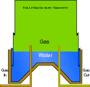 A two-lift telescopic gas holder, half raised
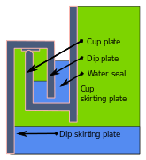 When the lift is engaged, it carries up with it a gas-tight seal of water.
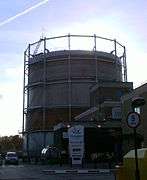 Column-guided gas holder at Cross Gates, Leeds. First of a former twin holder station built around 1900.
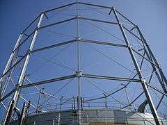 Another view of the gas holder at Cross Gates, Leeds
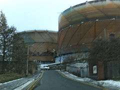
Dry-seal-type gas holder

Dry-seal gas holders have a static cylindrical shell, within which a piston rises and falls. As it moves, a grease seal, tar/oil seal or a sealing membrane which is rolled out and in from the piston keeps the gas from escaping. The MAN (Maschinenfabrik Augsburg-Nürnberg AG) was introduced in 1915: it was polygonal and used a tar/oil seal. The Klonne dry seal gas holder was circular: it used a grease seal. The Dry-seal Wiggins gas holder was patented in 1952: it used a flexible curtain that was suspended from the piston.[17] The largest low-pressure gas holders built was the Klonne gas holder built in 1938 in Gelsenkirchen. It was 147 metres (482 ft) high and 80 metres (260 ft) in diameter, which gave it a capacity of 594,000 cubic metres (21,000,000 cu ft). There was a MAN type, built in 1934 in Chicago with a capacity of 566,000 cubic metres (20,000,000 cu ft).[18]
By location
Europe
The pollution associated with gasworks and gas storage makes the land difficult to reclaim for other purposes, but some gas holders, notably in Vienna, have been converted into other uses such as living space and a shopping mall and historical archives for the city. Many sites, however, were never used for the production of 'town gas', therefore the land contamination is relatively low.
Gas holders have been a major part of the skylines of low-rise British cities for up to 200 years, due to their large distinctive shape and central location. They were originally used for balancing daily demand and generation of town gas. With the move to natural gas and construction of the national grid pipework, their use steadily diminished as the pipe network could both store gas under pressure, and eventually satisfy peak demand directly.[19] London, Manchester, Sheffield, Birmingham, Leeds, Newcastle, Salisbury and Glasgow (which has the largest gasometers in the UK[20]) are noted for having many gas holders.
Some of these gas holders have become listed buildings. The gas holders behind King's Cross station in London were specially dismantled when the new Channel Tunnel Rail Link was being created,[21] with Gas holder No 8 being re-erected on a nearby site behind St Pancras station as part of a housing development. It has been fashioned into a park.[22] Most gas holders are no longer used, and a program of dismantling is underway to release the land for reuse.[19]
A gasworks in South Lotts, Dublin, Ireland, was converted into apartments.[23]
In the past, holder stations would have an operator living on site controlling their movement. However, with the process control systems now used on these sites, such an operator is obsolete. The tallest gasometer in Europe is 117 metres (384 ft) tall and is located in Oberhausen.[24]
In the UK as well as other European countries, a movement to preserve classic gasometers has emerged in recent years, especially after Britain's National Grid announced in 2013 their plans to remove 76 gas holders, and soon afterwards, Southern and Scottish Gas networks announced that they would demolish 111 others. Christopher Costelloe, director of the Victorian Society, a leader in the campaign to preserve the gasometers said:
“Gasometers, by their very size and structure, cannot help but become landmarks. [They] are singularly dramatic structures for all their emptiness.”[25]
The gashouder in Amsterdam is notable for its Awakenings_feesten techno parties.
 The gas holders of Provan Gas Works, on the skyline in Glasgow; pipework and the booster house can also be seen.
 Gasometer of the MAN type in Stuttgart, Germany
- Four gas holders converted for residential and commercial use in Vienna
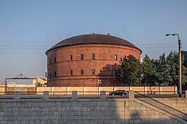 Gas holder in Saint Petersburg, Russia
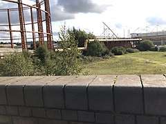 Two gas holders in Northam, Southampton. The gasworks is no longer standing
United States
.jpg)
Gasometers are comparatively rare in the United States. The most notable of these were erected in St. Louis by the Laclede Gas Light Company in the early 20th century. These gasometers remained in use until the early first decade of the 21st century, when the last one was decommissioned and abandoned in place. The most recently used gasometer in the United States was on the southeast side of Indianapolis, but it has been demolished along with adjoining the Citizens Energy Group coke plant. Another pair of holders at the Newtown Holder Station, in Elmhurst, Queens, in New York City, was a popular landmark for traffic reporters until they were demolished in 1996 and became Elmhurst Park. The demolition of two larger "Maspeth Tanks" in nearby Greenpoint, Brooklyn, was described by The New York Times at length.[26]
A large MAN-type gas holder was erected just east of Baltimore, Maryland, by Koppers Inc. in 1949 and operated by Baltimore Gas and Electric for thirty-two years. The 307-foot-tall (94 m), 170-foot-diameter (52 m) structure, which could hold 7 million cubic feet (200,000 m3), was a landmark due to its unusual marking scheme, which had a red-and-white checkerboard pattern from 200 feet (61 m) up. The structure was demolished in July 1984.
As of 2019, efforts were under way to save a gas holder building in Concord, New Hampshire. It is unusual because the cap is still in place.[27][28]
PG&E operated gas holders at its gasification plants in California before natural gas pipelines were built. The San Francisco Beach Street Plant was built in 1899; the gas plant operated until 1931, but its associated gas holder was used with natural gas into the 1950s, when the property was redeveloped.[29] Gas holders also previously existed at Chico (demolished 1951),[30] Daly City,[31] Eureka,[32] Fresno,[33] Merced,[34] Monterey,[35] Oakland,[36] Redding (gas holder demolished early 1960s),[37] Redwood City (gas holder built early 1900s, demolished 1959),[38] Salinas,[39] San Francisco Potrero Plant,[40] Santa Rosa,[41] St. Helena,[42] Stockton,[43] Vallejo,[44] Willows;[45] and likely existed at their other gasification plants in Colusa, Hollister, Lodi, Madera, Marysville, Modesto, Napa, Oakdale, Oroville, Red Bluff, Sacramento, San Luis Obispo, Santa Cruz, Selma, Tracy, Turlock, Watsonville and Woodland.[46]
Australia
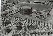
Gasholders, though once common, have become rare in Australia. Most gasworks within the country were demolished or repurposed, and few gasometers remain because of this. A good example of a largely intact gasometer is located at the Launceston Gasworks site in Tasmania. Though the gas bell has been removed, all other components are intact. The remains of two older 1860s gasometers are also visible on site but only the foundations remain.
Gasworks Newstead is a commercial, residential, and retail development adjoining the river at Newstead, Brisbane, Queensland, Australia, opening in 2013, built around a now heritage listed 1887 gas holder. Only the frame remains, inside of which is a plaza used as a public recreation zone and for occasional special events such as markets or concerts. At dusk each day a dynamic lighting display illuminates the frame. The former industrial site on the inner-city fringe became an urban renewal zone for upmarket housing centred on the Gasworks zone.
For many years, a huge gasholder towered over the Arden Street Oval, the home ground of the North Melbourne Football Club in the Victorian Football League. Television coverage of Australian Rules football matches played at the famous ground showed the gasholder dominating the landscape. It was demolished in late 1977/early 1978.
Other storage systems
Gas more recently was stored in large underground reservoirs such as salt caverns. In modern times, however, line-packing is the preferred method.
Throughout the 1960s and 1970s it was thought that gas holders could be replaced with high-pressure bullets (a cylindrical pressure vessel with hemispherical ends). However, regulations brought in meant that all new bullets must be built several miles out of towns and cities, and the security of storing large amounts of high-pressure natural gas above ground made them unpopular with local people and councils. Bullets are gradually being decommissioned. It is also possible to store natural gas in liquid form, and this is widely practised throughout the world.
See also
- Gasometer Oberhausen
- Gashouse District
- Natural gas storage
- Water tower, similar utility storage structures
- Gasværket - a theatre in Copenhagen which was formerly a huge gas holder
References
- Notes
- Thomas 2014, slides 5-7.
- Thomas 2014, slide 10.
- Thomas 2014, slide 8.
- Luigi Fiorinoa; Raffaele Landolfob; Federico Massimo Mazzolani (2014). "The refurbishment of gasometers as a relevant witness of industrial archaeology". Engineering Structures. 84: 252–265. doi:10.1016/j.engstruct.2014.11.035.
- Ram, Ed (9 February 2015). "Will the UK's gas holders be missed? BBC News". Magazine. BBC News. Retrieved 24 May 2016.CS1 maint: ref=harv (link)
- Thomas 2014, slides 8, 10-11.
- Thomas 2014, slide 11.
- "Greater Manchester Gazetteer". Greater Manchester County Record Office. Places names – M to N. Archived from the original on 11 February 2011. Retrieved 9 July 2007.
- Thomas 2014, slides 17.
- "Gasometers: a brief history".
- Thomas 2014, slide 12.
- Super User. "Gasholder types". motherwellbridge.com. Archived from the original on 4 December 2008. Retrieved 5 July 2015.
- Thomas 2010, p. 1.
- Thomas 2010, p. 8.
- Thomas 2010, p. 9.
- Thomas 2010, p. 11.
- Thomas 2014, p. 27.
- Thomas 2014, p. 10.
- "Will the UK's gas holders be missed?".
- "archiseek: The Gasworks, Dublin" (PDF).
- "St Pancras Gasometers". scribd.com. Retrieved 5 July 2015.
- "Historic Gasholder No8 at King's Cross". King's Cross. Retrieved 5 July 2015.
- "National Grid Gasholder Demolition Case Study". Archived from the original on 2012-07-23.
- "Gasometer Oberhausen".
- Sean O'Hagan, Gasworks wonders..., The Guardian, 14 June 2015.
- Newman, Andy (July 9, 2001). "Last Days for Brooklyn's Giants; Twin Tanks Carry a Love-Hate Reputation to the End". Archived from the original on 2014-05-29. Retrieved 2014-05-27.
- Concord Monitor: "Collapse of entrance roof at historic gasholder building reflects its problems" (March 29, 2016
- Concord Monitor: "Gasholder future still uncertain" (Jan. 6, 2019)
- "Former Beach Street Manufactured Gas Plant–San Francisco". www.pge.com. Retrieved 23 Jan 2019.
- "Former Colusa manufactured gas plant". www.pge.com. Retrieved 23 Jan 2019.
- "Former Daly City manufactured gas plant". www.pge.com. Retrieved 23 Jan 2019.
- "Former Eureka manufactured gas plant". www.pge.com. Retrieved 23 Jan 2019.
- "Former Fresno - 1 Manufactured Gas Plant". www.pge.com. Retrieved 23 Jan 2019."Former Fresno-2 Manufactured Gas Plant". www.pge.com. Retrieved 23 Jan 2019.
- "Former Merced manufactured gas plant". www.pge.com. Retrieved 23 Jan 2019.
- "Former Monterey manufactured gas plant". www.pge.com. Retrieved 23 Jan 2019.
- "Former Oakland manufactured gas plant". www.pge.com. Retrieved 23 Jan 2019.
- "Former Redding manufactured gas plant". www.pge.com. Retrieved 23 Jan 2019.
- "Former Redwood City gas holder". www.pge.com. Retrieved 23 Jan 2019.
- "Former Salinas manufactured gas plant". www.pge.com. Retrieved 23 Jan 2019.
- "Former Potrero Power Plant". www.pge.com. Retrieved 23 Jan 2019.
- "Former Santa Rosa manufactured gas plant". www.pge.com. Retrieved 23 Jan 2019.
- "Former St. Helena manufactured gas plant". www.pge.com. Retrieved 23 Jan 2019.
- "Former Stockton manufactured gas plant". www.pge.com. Retrieved 23 Jan 2019.
- "Former Vallejo manufactured gas plant". www.pge.com. Retrieved 23 Jan 2019.
- "Former Willows manufactured gas plant". www.pge.com. Retrieved 23 Jan 2019.
- "PG&E's manufactured gas plant program". www.pge.com. Retrieved 23 Jan 2019.
- Bibliography
- Thomas, Russell (2010). "Gasholders and their tanks" (PDF). Retrieved 25 May 2016.CS1 maint: ref=harv (link)
- Thomas, Russell (2014). "History of the Gasholder-a Powerpoint Presentation" (PDF). Retrieved 25 May 2016.CS1 maint: ref=harv (link)
Further reading
- "Steel making provides energy solution". newsteelconstruction.com. Retrieved 5 July 2015.
External links
| Wikimedia Commons has media related to Gasometers. |
| Wikimedia Commons has media related to Gasometer. |
- Use of gasometers in Oil & Gas industry
- Condemned: The great gasometer from BBC News, January 28, 1999
- Gasometer Augsburg in Germany and a list of many Gasometers in Europe
- Gasometer Schlieren, Switzerland
- "The rise and fall of gasometers" Extrageographic magazine
- Gasholders and their tanks
- Early London Gas Industry
- Visits_to_Works 1894_Institution_of_Mechanical_Engineers: including Manchester and Salford Gas Works
