Polarization (waves)
Polarization (also polarisation) is a property applying to transverse waves that specifies the geometrical orientation of the oscillations.[1][2][3][4][5] In a transverse wave, the direction of the oscillation is perpendicular to the direction of motion of the wave.[4] A simple example of a polarized transverse wave is vibrations traveling along a taut string (see image); for example, in a musical instrument like a guitar string. Depending on how the string is plucked, the vibrations can be in a vertical direction, horizontal direction, or at any angle perpendicular to the string. In contrast, in longitudinal waves, such as sound waves in a liquid or gas, the displacement of the particles in the oscillation is always in the direction of propagation, so these waves do not exhibit polarization. Transverse waves that exhibit polarization include electromagnetic waves such as light and radio waves, gravitational waves,[6] and transverse sound waves (shear waves) in solids.

An electromagnetic wave such as light consists of a coupled oscillating electric field and magnetic field which are always perpendicular to each other; by convention, the "polarization" of electromagnetic waves refers to the direction of the electric field. In linear polarization, the fields oscillate in a single direction. In circular or elliptical polarization, the fields rotate at a constant rate in a plane as the wave travels. The rotation can have two possible directions; if the fields rotate in a right hand sense with respect to the direction of wave travel, it is called right circular polarization, while if the fields rotate in a left hand sense, it is called left circular polarization.
Light or other electromagnetic radiation from many sources, such as the sun, flames, and incandescent lamps, consists of short wave trains with an equal mixture of polarizations; this is called unpolarized light. Polarized light can be produced by passing unpolarized light through a polarizer, which allows waves of only one polarization to pass through. The most common optical materials do not affect the polarization of light, however, some materials—those that exhibit birefringence, dichroism, or optical activity—affect light differently depending on its polarization. Some of these are used to make polarizing filters. Light is also partially polarized when it reflects from a surface.
According to quantum mechanics, electromagnetic waves can also be viewed as streams of particles called photons. When viewed in this way, the polarization of an electromagnetic wave is determined by a quantum mechanical property of photons called their spin.[7][8] A photon has one of two possible spins: it can either spin in a right hand sense or a left hand sense about its direction of travel. Circularly polarized electromagnetic waves are composed of photons with only one type of spin, either right- or left-hand. Linearly polarized waves consist of photons that are in a superposition of right and left circularly polarized states, with equal amplitude and phases synchronized to give oscillation in a plane.[8]
Polarization is an important parameter in areas of science dealing with transverse waves, such as optics, seismology, radio, and microwaves. Especially impacted are technologies such as lasers, wireless and optical fiber telecommunications, and radar.
Introduction
Wave propagation and polarization
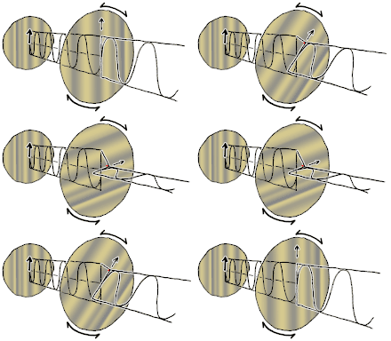
Most sources of light are classified as incoherent and unpolarized (or only "partially polarized") because they consist of a random mixture of waves having different spatial characteristics, frequencies (wavelengths), phases, and polarization states. However, for understanding electromagnetic waves and polarization in particular, it is easier to just consider coherent plane waves; these are sinusoidal waves of one particular direction (or wavevector), frequency, phase, and polarization state. Characterizing an optical system in relation to a plane wave with those given parameters can then be used to predict its response to a more general case, since a wave with any specified spatial structure can be decomposed into a combination of plane waves (its so-called angular spectrum). Incoherent states can be modeled stochastically as a weighted combination of such uncorrelated waves with some distribution of frequencies (its spectrum), phases, and polarizations.
Transverse electromagnetic waves

Electromagnetic waves (such as light), traveling in free space or another homogeneous isotropic non-attenuating medium, are properly described as transverse waves, meaning that a plane wave's electric field vector E and magnetic field H are in directions perpendicular to (or "transverse" to) the direction of wave propagation; E and H are also perpendicular to each other. By convention, the "polarization" direction of an electromagnetic wave is given by its electric field vector. Considering a monochromatic plane wave of optical frequency f (light of vacuum wavelength λ has a frequency of f = c/λ where c is the speed of light), let us take the direction of propagation as the z axis. Being a transverse wave the E and H fields must then contain components only in the x and y directions whereas Ez = Hz = 0. Using complex (or phasor) notation, the instantaneous physical electric and magnetic fields are given by the real parts of the complex quantities occurring in the following equations. As a function of time t and spatial position z (since for a plane wave in the +z direction the fields have no dependence on x or y) these complex fields can be written as:
and
where λ = λ0/n is the wavelength in the medium (whose refractive index is n) and T = 1/f is the period of the wave. Here ex, ey, hx, and hy are complex numbers. In the second more compact form, as these equations are customarily expressed, these factors are described using the wavenumber and angular frequency (or "radian frequency") . In a more general formulation with propagation not restricted to the +z direction, then the spatial dependence kz is replaced by where is called the wave vector, the magnitude of which is the wavenumber.
Thus the leading vectors e and h each contain up to two nonzero (complex) components describing the amplitude and phase of the wave's x and y polarization components (again, there can be no z polarization component for a transverse wave in the +z direction). For a given medium with a characteristic impedance , h is related to e by:
and
- .
In a dielectric, η is real and has the value η0/n, where n is the refractive index and η0 is the impedance of free space. The impedance will be complex in a conducting medium. Note that given that relationship, the dot product of E and H must be zero:
indicating that these vectors are orthogonal (at right angles to each other), as expected.
So knowing the propagation direction (+z in this case) and η, one can just as well specify the wave in terms of just ex and ey describing the electric field. The vector containing ex and ey (but without the z component which is necessarily zero for a transverse wave) is known as a Jones vector. In addition to specifying the polarization state of the wave, a general Jones vector also specifies the overall magnitude and phase of that wave. Specifically, the intensity of the light wave is proportional to the sum of the squared magnitudes of the two electric field components:
however the wave's state of polarization is only dependent on the (complex) ratio of ey to ex. So let us just consider waves whose |ex|2 + |ey|2 = 1; this happens to correspond to an intensity of about .00133 watts per square meter in free space (where ). And since the absolute phase of a wave is unimportant in discussing its polarization state, let us stipulate that the phase of ex is zero, in other words ex is a real number while ey may be complex. Under these restrictions, ex and ey can be represented as follows:
where the polarization state is now fully parameterized by the value of Q (such that −1 < Q < 1) and the relative phase .
Non-transverse waves
In addition to transverse waves, there are many wave motions where the oscillation is not limited to directions perpendicular to the direction of propagation. These cases are far beyond the scope of the current article which concentrates on transverse waves (such as most electromagnetic waves in bulk media), however one should be aware of cases where the polarization of a coherent wave cannot be described simply using a Jones vector, as we have just done.
Just considering electromagnetic waves, we note that the preceding discussion strictly applies to plane waves in a homogeneous isotropic non-attenuating medium, whereas in an anisotropic medium (such as birefringent crystals as discussed below) the electric or magnetic field may have longitudinal as well as transverse components. In those cases the electric displacement D and magnetic flux density B still obey the above geometry but due to anisotropy in the electric susceptibility (or in the magnetic permeability), now given by a tensor, the direction of E (or H) may differ from that of D (or B). Even in isotropic media, so-called inhomogeneous waves can be launched into a medium whose refractive index has a significant imaginary part (or "extinction coefficient") such as metals; these fields are also not strictly transverse.[9]:179–184[10]:51–52 Surface waves or waves propagating in a waveguide (such as an optical fiber) are generally not transverse waves, but might be described as an electric or magnetic transverse mode, or a hybrid mode.
Even in free space, longitudinal field components can be generated in focal regions, where the plane wave approximation breaks down. An extreme example is radially or tangentially polarized light, at the focus of which the electric or magnetic field respectively is entirely longitudinal (along the direction of propagation).[11]
For longitudinal waves such as sound waves in fluids, the direction of oscillation is by definition along the direction of travel, so the issue of polarization is not normally even mentioned. On the other hand, sound waves in a bulk solid can be transverse as well as longitudinal, for a total of three polarization components. In this case, the transverse polarization is associated with the direction of the shear stress and displacement in directions perpendicular to the propagation direction, while the longitudinal polarization describes compression of the solid and vibration along the direction of propagation. The differential propagation of transverse and longitudinal polarizations is important in seismology.
Polarization state

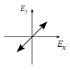
Polarization is best understood by initially considering only pure polarization states, and only a coherent sinusoidal wave at some optical frequency. The vector in the adjacent diagram might describe the oscillation of the electric field emitted by a single-mode laser (whose oscillation frequency would be typically 1015 times faster). The field oscillates in the x-y plane, along the page, with the wave propagating in the z direction, perpendicular to the page. The first two diagrams below trace the electric field vector over a complete cycle for linear polarization at two different orientations; these are each considered a distinct state of polarization (SOP). Note that the linear polarization at 45° can also be viewed as the addition of a horizontally linearly polarized wave (as in the leftmost figure) and a vertically polarized wave of the same amplitude in the same phase.



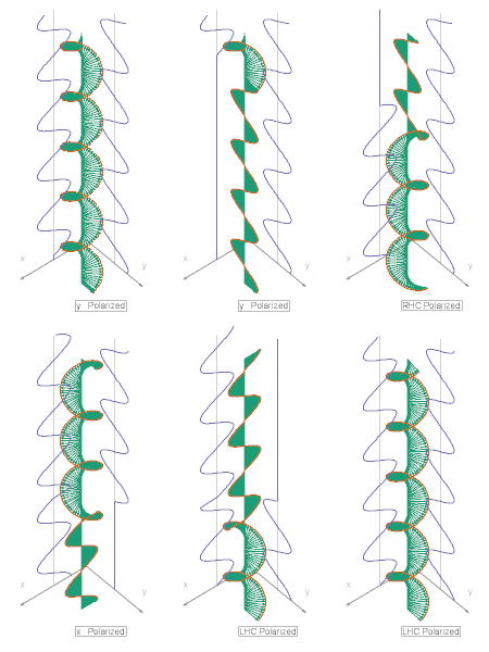
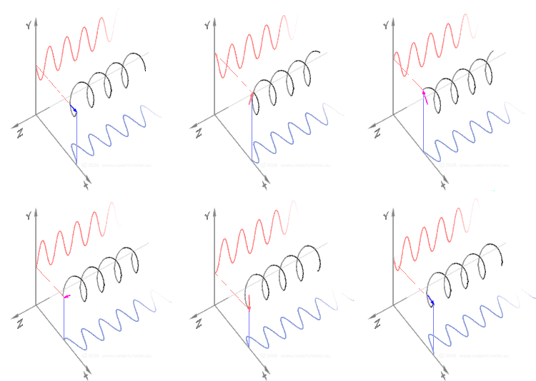
Now if one were to introduce a phase shift in between those horizontal and vertical polarization components, one would generally obtain elliptical polarization[12] as is shown in the third figure. When the phase shift is exactly ±90°, then circular polarization is produced (fourth and fifth figures). Thus is circular polarization created in practice, starting with linearly polarized light and employing a quarter-wave plate to introduce such a phase shift. The result of two such phase-shifted components in causing a rotating electric field vector is depicted in the animation on the right. Note that circular or elliptical polarization can involve either a clockwise or counterclockwise rotation of the field. These correspond to distinct polarization states, such as the two circular polarizations shown above.
Of course the orientation of the x and y axes used in this description is arbitrary. The choice of such a coordinate system and viewing the polarization ellipse in terms of the x and y polarization components, corresponds to the definition of the Jones vector (below) in terms of those basis polarizations. One would typically choose axes to suit a particular problem such as x being in the plane of incidence. Since there are separate reflection coefficients for the linear polarizations in and orthogonal to the plane of incidence (p and s polarizations, see below), that choice greatly simplifies the calculation of a wave's reflection from a surface.
Moreover, one can use as basis functions any pair of orthogonal polarization states, not just linear polarizations. For instance, choosing right and left circular polarizations as basis functions simplifies the solution of problems involving circular birefringence (optical activity) or circular dichroism.
Polarization ellipse
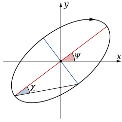
Consider a purely polarized monochromatic wave. If one were to plot the electric field vector over one cycle of oscillation, an ellipse would generally be obtained, as is shown in the figure, corresponding to a particular state of elliptical polarization. Note that linear polarization and circular polarization can be seen as special cases of elliptical polarization.
A polarization state can then be described in relation to the geometrical parameters of the ellipse, and its "handedness", that is, whether the rotation around the ellipse is clockwise or counter clockwise. One parameterization of the elliptical figure specifies the orientation angle ψ, defined as the angle between the major axis of the ellipse and the x-axis[13] along with the ellipticity ε=a/b, the ratio of the ellipse's major to minor axis.[14][15][16] (also known as the axial ratio). The ellipticity parameter is an alternative parameterization of an ellipse's eccentricity , or the ellipticity angle, χ = arctan b/a= arctan 1/ε as is shown in the figure.[13] The angle χ is also significant in that the latitude (angle from the equator) of the polarization state as represented on the Poincaré sphere (see below) is equal to ±2χ. The special cases of linear and circular polarization correspond to an ellipticity ε of infinity and unity (or χ of zero and 45°) respectively.
Jones vector
Full information on a completely polarized state is also provided by the amplitude and phase of oscillations in two components of the electric field vector in the plane of polarization. This representation was used above to show how different states of polarization are possible. The amplitude and phase information can be conveniently represented as a two-dimensional complex vector (the Jones vector):
Here and denote the amplitude of the wave in the two components of the electric field vector, while and represent the phases. The product of a Jones vector with a complex number of unit modulus gives a different Jones vector representing the same ellipse, and thus the same state of polarization. The physical electric field, as the real part of the Jones vector, would be altered but the polarization state itself is independent of absolute phase. The basis vectors used to represent the Jones vector need not represent linear polarization states (i.e. be real). In general any two orthogonal states can be used, where an orthogonal vector pair is formally defined as one having a zero inner product. A common choice is left and right circular polarizations, for example to model the different propagation of waves in two such components in circularly birefringent media (see below) or signal paths of coherent detectors sensitive to circular polarization.
Coordinate frame
Regardless of whether polarization state is represented using geometric parameters or Jones vectors, implicit in the parameterization is the orientation of the coordinate frame. This permits a degree of freedom, namely rotation about the propagation direction. When considering light that is propagating parallel to the surface of the Earth, the terms "horizontal" and "vertical" polarization are often used, with the former being associated with the first component of the Jones vector, or zero azimuth angle. On the other hand, in astronomy the equatorial coordinate system is generally used instead, with the zero azimuth (or position angle, as it is more commonly called in astronomy to avoid confusion with the horizontal coordinate system) corresponding to due north.
s and p designations
Another coordinate system frequently used relates to the plane of incidence. This is the plane made by the incoming propagation direction and the vector perpendicular to the plane of an interface, in other words, the plane in which the ray travels before and after reflection or refraction. The component of the electric field parallel to this plane is termed p-like (parallel) and the component perpendicular to this plane is termed s-like (from senkrecht, German for perpendicular). Polarized light with its electric field along the plane of incidence is thus denoted p-polarized, while light whose electric field is normal to the plane of incidence is called s-polarized. P polarization is commonly referred to as transverse-magnetic (TM), and has also been termed pi-polarized or tangential plane polarized. S polarization is also called transverse-electric (TE), as well as sigma-polarized or sagittal plane polarized.
Unpolarized and partially polarized light
Definition
Natural light, like most other common sources of visible light, is incoherent: radiation is produced independently by a large number of atoms or molecules whose emissions are uncorrelated and generally of random polarizations. In this case the light is said to be unpolarized. This term is somewhat inexact, since at any instant of time at one location there is a definite direction to the electric and magnetic fields, however it implies that the polarization changes so quickly in time that it will not be measured or relevant to the outcome of an experiment. A so-called depolarizer acts on a polarized beam to create one which is actually fully polarized at every point, but in which the polarization varies so rapidly across the beam that it may be ignored in the intended applications.
Unpolarized light can be described as a mixture of two independent oppositely polarized streams, each with half the intensity.[17][18] Light is said to be partially polarized when there is more power in one of these streams than the other. At any particular wavelength, partially polarized light can be statistically described as the superposition of a completely unpolarized component and a completely polarized one.[19]:330 One may then describe the light in terms of the degree of polarization and the parameters of the polarized component. That polarized component can be described in terms of a Jones vector or polarization ellipse, as is detailed above. However, in order to also describe the degree of polarization, one normally employs Stokes parameters (see below) to specify a state of partial polarization.[19]:351,374–375
Motivation
The transmission of plane waves through a homogeneous medium are fully described in terms of Jones vectors and 2×2 Jones matrices. However, in practice there are cases in which all of the light cannot be viewed in such a simple manner due to spatial inhomogeneities or the presence of mutually incoherent waves. So-called depolarization, for instance, cannot be described using Jones matrices. For these cases it is usual instead to use a 4×4 matrix that acts upon the Stokes 4-vector. Such matrices were first used by Paul Soleillet in 1929, although they have come to be known as Mueller matrices. While every Jones matrix has a Mueller matrix, the reverse is not true. Mueller matrices are then used to describe the observed polarization effects of the scattering of waves from complex surfaces or ensembles of particles, as shall now be presented.[19]:377–379
Coherency matrix
The Jones vector perfectly describes the state of polarization and phase of a single monochromatic wave, representing a pure state of polarization as described above. However any mixture of waves of different polarizations (or even of different frequencies) do not correspond to a Jones vector. In so-called partially polarized radiation the fields are stochastic, and the variations and correlations between components of the electric field can only be described statistically. One such representation is the coherency matrix:[20]:137–142
where angular brackets denote averaging over many wave cycles. Several variants of the coherency matrix have been proposed: the Wiener coherency matrix and the spectral coherency matrix of Richard Barakat measure the coherence of a spectral decomposition of the signal, while the Wolf coherency matrix averages over all time/frequencies.
The coherency matrix contains all second order statistical information about the polarization. This matrix can be decomposed into the sum of two idempotent matrices, corresponding to the eigenvectors of the coherency matrix, each representing a polarization state that is orthogonal to the other. An alternative decomposition is into completely polarized (zero determinant) and unpolarized (scaled identity matrix) components. In either case, the operation of summing the components corresponds to the incoherent superposition of waves from the two components. The latter case gives rise to the concept of the "degree of polarization"; i.e., the fraction of the total intensity contributed by the completely polarized component.
Stokes parameters
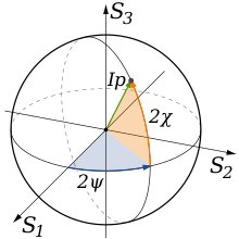
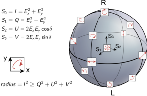
The coherency matrix is not easy to visualize, and it is therefore common to describe incoherent or partially polarized radiation in terms of its total intensity (I), (fractional) degree of polarization (p), and the shape parameters of the polarization ellipse. An alternative and mathematically convenient description is given by the Stokes parameters, introduced by George Gabriel Stokes in 1852. The relationship of the Stokes parameters to intensity and polarization ellipse parameters is shown in the equations and figure below.
Here Ip, 2ψ and 2χ are the spherical coordinates of the polarization state in the three-dimensional space of the last three Stokes parameters. Note the factors of two before ψ and χ corresponding respectively to the facts that any polarization ellipse is indistinguishable from one rotated by 180°, or one with the semi-axis lengths swapped accompanied by a 90° rotation. The Stokes parameters are sometimes denoted I, Q, U and V.
Poincaré sphere
Neglecting the first Stokes parameter S0 (or I), the three other Stokes parameters can be plotted directly in three-dimensional Cartesian coordinates. For a given power in the polarized component given by
the set of all polarization states are then mapped to points on the surface of the so-called Poincaré sphere (but of radius P), as shown in the accompanying diagram.
Often the total beam power is not of interest, in which case a normalized Stokes vector is used by dividing the Stokes vector by the total intensity S0:
The normalized Stokes vector then has unity power () and the three significant Stokes parameters plotted in three dimensions will lie on the unity-radius Poincaré sphere for pure polarization states (where ). Partially polarized states will lie inside the Poincaré sphere at a distance of from the origin. When the non-polarized component is not of interest, the Stokes vector can be further normalized to obtain
When plotted, that point will lie on the surface of the unity-radius Poincaré sphere and indicate the state of polarization of the polarized component.
Any two antipodal points on the Poincaré sphere refer to orthogonal polarization states. The overlap between any two polarization states is dependent solely on the distance between their locations along the sphere. This property, which can only be true when pure polarization states are mapped onto a sphere, is the motivation for the invention of the Poincaré sphere and the use of Stokes parameters, which are thus plotted on (or beneath) it.
Note that the IEEE defines RHCP and LHCP the opposite as those used by Physicists. The IEEE 1979 Antenna Standard will show RHCP on the South Pole of the Poincare Sphere. The IEEE defines RHCP using the right hand with thumb pointing in the direction of transmit, and the fingers showing the direction of rotation of the E field with time. The rationale for the opposite conventions used by Physicists and Engineers is that Astronomical Observations are always done with the incoming wave traveling toward the observer, where as for most engineers, they are assumed to be standing behind the transmitter watching the wave traveling away from them. This article is not using the IEEE 1979 Antenna Standard and is not using the +t convention typically used in IEEE work.
Implications for reflection and propagation
Polarization in wave propagation
In a vacuum, the components of the electric field propagate at the speed of light, so that the phase of the wave varies in space and time while the polarization state does not. That is, the electric field vector e of a plane wave in the +z direction follows:
where k is the wavenumber. As noted above, the instantaneous electric field is the real part of the product of the Jones vector times the phase factor . When an electromagnetic wave interacts with matter, its propagation is altered according to the material's (complex) index of refraction. When the real or imaginary part of that refractive index is dependent on the polarization state of a wave, properties known as birefringence and polarization dichroism (or diattenuation) respectively, then the polarization state of a wave will generally be altered.
In such media, an electromagnetic wave with any given state of polarization may be decomposed into two orthogonally polarized components that encounter different propagation constants. The effect of propagation over a given path on those two components is most easily characterized in the form of a complex 2×2 transformation matrix J known as a Jones matrix:
The Jones matrix due to passage through a transparent material is dependent on the propagation distance as well as the birefringence. The birefringence (as well as the average refractive index) will generally be dispersive, that is, it will vary as a function of optical frequency (wavelength). In the case of non-birefringent materials, however, the 2×2 Jones matrix is the identity matrix (multiplied by a scalar phase factor and attenuation factor), implying no change in polarization during propagation.
For propagation effects in two orthogonal modes, the Jones matrix can be written as
where g1 and g2 are complex numbers describing the phase delay and possibly the amplitude attenuation due to propagation in each of the two polarization eigenmodes. T is a unitary matrix representing a change of basis from these propagation modes to the linear system used for the Jones vectors; in the case of linear birefringence or diattenuation the modes are themselves linear polarization states so T and T−1 can be omitted if the coordinate axes have been chosen appropriately.
Birefringence
In media termed birefringent, in which the amplitudes are unchanged but a differential phase delay occurs, the Jones matrix is a unitary matrix: |g1| = |g2| = 1. Media termed diattenuating (or dichroic in the sense of polarization), in which only the amplitudes of the two polarizations are affected differentially, may be described using a Hermitian matrix (generally multiplied by a common phase factor). In fact, since any matrix may be written as the product of unitary and positive Hermitian matrices, light propagation through any sequence of polarization-dependent optical components can be written as the product of these two basic types of transformations.
In birefringent media there is no attenuation, but two modes accrue a differential phase delay. Well known manifestations of linear birefringence (that is, in which the basis polarizations are orthogonal linear polarizations) appear in optical wave plates/retarders and many crystals. If linearly polarized light passes through a birefringent material, its state of polarization will generally change, unless its polarization direction is identical to one of those basis polarizations. Since the phase shift, and thus the change in polarization state, is usually wavelength-dependent, such objects viewed under white light in between two polarizers may give rise to colorful effects, as seen in the accompanying photograph.
Circular birefringence is also termed optical activity, especially in chiral fluids, or Faraday rotation, when due to the presence of a magnetic field along the direction of propagation. When linearly polarized light is passed through such an object, it will exit still linearly polarized, but with the axis of polarization rotated. A combination of linear and circular birefringence will have as basis polarizations two orthogonal elliptical polarizations; however, the term "elliptical birefringence" is rarely used.
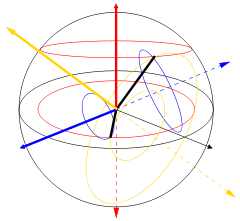
One can visualize the case of linear birefringence (with two orthogonal linear propagation modes) with an incoming wave linearly polarized at a 45° angle to those modes. As a differential phase starts to accrue, the polarization becomes elliptical, eventually changing to purely circular polarization (90° phase difference), then to elliptical and eventually linear polarization (180° phase) perpendicular to the original polarization, then through circular again (270° phase), then elliptical with the original azimuth angle, and finally back to the original linearly polarized state (360° phase) where the cycle begins anew. In general the situation is more complicated and can be characterized as a rotation in the Poincaré sphere about the axis defined by the propagation modes. Examples for linear (blue), circular (red), and elliptical (yellow) birefringence are shown in the figure on the left. The total intensity and degree of polarization are unaffected. If the path length in the birefringent medium is sufficient, the two polarization components of a collimated beam (or ray) can exit the material with a positional offset, even though their final propagation directions will be the same (assuming the entrance face and exit face are parallel). This is commonly viewed using calcite crystals, which present the viewer with two slightly offset images, in opposite polarizations, of an object behind the crystal. It was this effect that provided the first discovery of polarization, by Erasmus Bartholinus in 1669.
Dichroism
Media in which transmission of one polarization mode is preferentially reduced are called dichroic or diattenuating. Like birefringence, diattenuation can be with respect to linear polarization modes (in a crystal) or circular polarization modes (usually in a liquid).
Devices that block nearly all of the radiation in one mode are known as polarizing filters or simply "polarizers". This corresponds to g2=0 in the above representation of the Jones matrix. The output of an ideal polarizer is a specific polarization state (usually linear polarization) with an amplitude equal to the input wave's original amplitude in that polarization mode. Power in the other polarization mode is eliminated. Thus if unpolarized light is passed through an ideal polarizer (where g1=1 and g2=0) exactly half of its initial power is retained. Practical polarizers, especially inexpensive sheet polarizers, have additional loss so that g1 < 1. However, in many instances the more relevant figure of merit is the polarizer's degree of polarization or extinction ratio, which involve a comparison of g1 to g2. Since Jones vectors refer to waves' amplitudes (rather than intensity), when illuminated by unpolarized light the remaining power in the unwanted polarization will be (g2/g1)2 of the power in the intended polarization.
Specular reflection
In addition to birefringence and dichroism in extended media, polarization effects describable using Jones matrices can also occur at (reflective) interface between two materials of different refractive index. These effects are treated by the Fresnel equations. Part of the wave is transmitted and part is reflected; for a given material those proportions (and also the phase of reflection) are dependent on the angle of incidence and are different for the s and p polarizations. Therefore, the polarization state of reflected light (even if initially unpolarized) is generally changed.
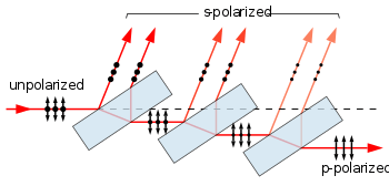
Any light striking a surface at a special angle of incidence known as Brewster's angle, where the reflection coefficient for p polarization is zero, will be reflected with only the s-polarization remaining. This principle is employed in the so-called "pile of plates polarizer" (see figure) in which part of the s polarization is removed by reflection at each Brewster angle surface, leaving only the p polarization after transmission through many such surfaces. The generally smaller reflection coefficient of the p polarization is also the basis of polarized sunglasses; by blocking the s (horizontal) polarization, most of the glare due to reflection from a wet street, for instance, is removed.[19]:348–350
In the important special case of reflection at normal incidence (not involving anisotropic materials) there is no particular s or p polarization. Both the x and y polarization components are reflected identically, and therefore the polarization of the reflected wave is identical to that of the incident wave. However, in the case of circular (or elliptical) polarization, the handedness of the polarization state is thereby reversed, since by convention this is specified relative to the direction of propagation. The circular rotation of the electric field around the x-y axes called "right-handed" for a wave in the +z direction is "left-handed" for a wave in the -z direction. But in the general case of reflection at a nonzero angle of incidence, no such generalization can be made. For instance, right-circularly polarized light reflected from a dielectric surface at a grazing angle, will still be right-handed (but elliptically) polarized. Linear polarized light reflected from a metal at non-normal incidence will generally become elliptically polarized. These cases are handled using Jones vectors acted upon by the different Fresnel coefficients for the s and p polarization components.
Measurement techniques involving polarization
Some optical measurement techniques are based on polarization. In many other optical techniques polarization is crucial or at least must be taken into account and controlled; such examples are too numerous to mention.
Measurement of stress
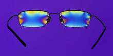
In engineering, the phenomenon of stress induced birefringence allows for stresses in transparent materials to be readily observed. As noted above and seen in the accompanying photograph, the chromaticity of birefringence typically creates colored patterns when viewed in between two polarizers. As external forces are applied, internal stress induced in the material is thereby observed. Additionally, birefringence is frequently observed due to stresses "frozen in" at the time of manufacture. This is famously observed in cellophane tape whose birefringence is due to the stretching of the material during the manufacturing process.
Ellipsometry
Ellipsometry is a powerful technique for the measurement of the optical properties of a uniform surface. It involves measuring the polarization state of light following specular reflection from such a surface. This is typically done as a function of incidence angle or wavelength (or both). Since ellipsometry relies on reflection, it is not required for the sample to be transparent to light or for its back side to be accessible.
Ellipsometry can be used to model the (complex) refractive index of a surface of a bulk material. It is also very useful in determining parameters of one or more thin film layers deposited on a substrate. Due to their reflection properties, not only are the predicted magnitude of the p and s polarization components, but their relative phase shifts upon reflection, compared to measurements using an ellipsometer. A normal ellipsometer does not measure the actual reflection coefficient (which requires careful photometric calibration of the illuminating beam) but the ratio of the p and s reflections, as well as change of polarization ellipticity (hence the name) induced upon reflection by the surface being studied. In addition to use in science and research, ellipsometers are used in situ to control production processes for instance.[21]:585ff[22]:632
Geology

The property of (linear) birefringence is widespread in crystalline minerals, and indeed was pivotal in the initial discovery of polarization. In mineralogy, this property is frequently exploited using polarization microscopes, for the purpose of identifying minerals. See optical mineralogy for more details.[23]:163–164
Sound waves in solid materials exhibit polarization. Differential propagation of the three polarizations through the earth is a crucial in the field of seismology. Horizontally and vertically polarized seismic waves (shear waves)are termed SH and SV, while waves with longitudinal polarization (compressional waves) are termed P-waves.[24]:48–50[25]:56–57
Chemistry
We have seen (above) that the birefringence of a type of crystal is useful in identifying it, and thus detection of linear birefringence is especially useful in geology and mineralogy. Linearly polarized light generally has its polarization state altered upon transmission through such a crystal, making it stand out when viewed in between two crossed polarizers, as seen in the photograph, above. Likewise, in chemistry, rotation of polarization axes in a liquid solution can be a useful measurement. In a liquid, linear birefringence is impossible, however there may be circular birefringence when a chiral molecule is in solution. When the right and left handed enantiomers of such a molecule are present in equal numbers (a so-called racemic mixture) then their effects cancel out. However, when there is only one (or a preponderance of one), as is more often the case for organic molecules, a net circular birefringence (or optical activity) is observed, revealing the magnitude of that imbalance (or the concentration of the molecule itself, when it can be assumed that only one enantiomer is present). This is measured using a polarimeter in which polarized light is passed through a tube of the liquid, at the end of which is another polarizer which is rotated in order to null the transmission of light through it.[19]:360–365[26]
Astronomy
In many areas of astronomy, the study of polarized electromagnetic radiation from outer space is of great importance. Although not usually a factor in the thermal radiation of stars, polarization is also present in radiation from coherent astronomical sources (e.g. hydroxyl or methanol masers), and incoherent sources such as the large radio lobes in active galaxies, and pulsar radio radiation (which may, it is speculated, sometimes be coherent), and is also imposed upon starlight by scattering from interstellar dust. Apart from providing information on sources of radiation and scattering, polarization also probes the interstellar magnetic field via Faraday rotation.[27]:119,124[28]:336–337 The polarization of the cosmic microwave background is being used to study the physics of the very early universe.[29][30] Synchrotron radiation is inherently polarised. It has been suggested that astronomical sources caused the chirality of biological molecules on Earth.[31]
Applications and examples
Polarized sunglasses

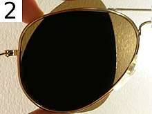
Unpolarized light, after being reflected by a specular (shiny) surface, generally obtains a degree of polarization. This phenomenon was observed in 1808 by the mathematician Étienne-Louis Malus, after whom Malus's law is named. Polarizing sunglasses exploit this effect to reduce glare from reflections by horizontal surfaces, notably the road ahead viewed at a grazing angle.
Wearers of polarized sunglasses will occasionally observe inadvertent polarization effects such as color-dependent birefringent effects, for example in toughened glass (e.g., car windows) or items made from transparent plastics, in conjunction with natural polarization by reflection or scattering. The polarized light from LCD monitors (see below) is very conspicuous when these are worn.
Sky polarization and photography

Polarization is observed in the light of the sky, as this is due to sunlight scattered by aerosols as it passes through the earth's atmosphere. The scattered light produces the brightness and color in clear skies. This partial polarization of scattered light can be used to darken the sky in photographs, increasing the contrast. This effect is most strongly observed at points on the sky making a 90° angle to the sun. Polarizing filters use these effects to optimize the results of photographing scenes in which reflection or scattering by the sky is involved.[19]:346–347[32]:495–499
Sky polarization has been used for orientation in navigation. The Pfund sky compass was used in the 1950s when navigating near the poles of the Earth's magnetic field when neither the sun nor stars were visible (e.g., under daytime cloud or twilight). It has been suggested, controversially, that the Vikings exploited a similar device (the "sunstone") in their extensive expeditions across the North Atlantic in the 9th–11th centuries, before the arrival of the magnetic compass from Asia to Europe in the 12th century. Related to the sky compass is the "polar clock", invented by Charles Wheatstone in the late 19th century.[33]:67–69
Display technologies
The principle of liquid-crystal display (LCD) technology relies on the rotation of the axis of linear polarization by the liquid crystal array. Light from the backlight (or the back reflective layer, in devices not including or requiring a backlight) first passes through a linear polarizing sheet. That polarized light passes through the actual liquid crystal layer which may be organized in pixels (for a TV or computer monitor) or in another format such as a seven-segment display or one with custom symbols for a particular product. The liquid crystal layer is produced with a consistent right (or left) handed chirality, essentially consisting of tiny helices. This causes circular birefringence, and is engineered so that there is a 90 degree rotation of the linear polarization state. However, when a voltage is applied across a cell, the molecules straighten out, lessening or totally losing the circular birefringence. On the viewing side of the display is another linear polarizing sheet, usually oriented at 90 degrees from the one behind the active layer. Therefore, when the circular birefringence is removed by the application of a sufficient voltage, the polarization of the transmitted light remains at right angles to the front polarizer, and the pixel appears dark. With no voltage, however, the 90 degree rotation of the polarization causes it to exactly match the axis of the front polarizer, allowing the light through. Intermediate voltages create intermediate rotation of the polarization axis and the pixel has an intermediate intensity. Displays based on this principle are widespread, and now are used in the vast majority of televisions, computer monitors and video projectors, rendering the previous CRT technology essentially obsolete. The use of polarization in the operation of LCD displays is immediately apparent to someone wearing polarized sunglasses, often making the display unreadable.
In a totally different sense, polarization encoding has become the leading (but not sole) method for delivering separate images to the left and right eye in stereoscopic displays used for 3D movies. This involves separate images intended for each eye either projected from two different projectors with orthogonally oriented polarizing filters or, more typically, from a single projector with time multiplexed polarization (a fast alternating polarization device for successive frames). Polarized 3D glasses with suitable polarizing filters ensure that each eye receives only the intended image. Historically such systems used linear polarization encoding because it was inexpensive and offered good separation. However circular polarization makes separation of the two images insensitive to tilting of the head, and is widely used in 3-D movie exhibition today, such as the system from RealD. Projecting such images requires screens that maintain the polarization of the projected light when viewed in reflection (such as silver screens); a normal diffuse white projection screen causes depolarization of the projected images, making it unsuitable for this application.
Although now obsolete, CRT computer displays suffered from reflection by the glass envelope, causing glare from room lights and consequently poor contrast. Several anti-reflection solutions were employed to ameliorate this problem. One solution utilized the principle of reflection of circularly polarized light. A circular polarizing filter in front of the screen allows for the transmission of (say) only right circularly polarized room light. Now, right circularly polarized light (depending on the convention used) has its electric (and magnetic) field direction rotating clockwise while propagating in the +z direction. Upon reflection, the field still has the same direction of rotation, but now propagation is in the −z direction making the reflected wave left circularly polarized. With the right circular polarization filter placed in front of the reflecting glass, the unwanted light reflected from the glass will thus be in very polarization state that is blocked by that filter, eliminating the reflection problem. The reversal of circular polarization on reflection and elimination of reflections in this manner can be easily observed by looking in a mirror while wearing 3-D movie glasses which employ left- and right-handed circular polarization in the two lenses. Closing one eye, the other eye will see a reflection in which it cannot see itself; that lens appears black. However the other lens (of the closed eye) will have the correct circular polarization allowing the closed eye to be easily seen by the open one.
Radio transmission and reception
All radio (and microwave) antennas used for transmitting or receiving are intrinsically polarized. They transmit in (or receive signals from) a particular polarization, being totally insensitive to the opposite polarization; in certain cases that polarization is a function of direction. Most antennas are nominally linearly polarized, but elliptical and circular polarization is a possibility. As is the convention in optics, the "polarization" of a radio wave is understood to refer to the polarization of its electric field, with the magnetic field being at a 90 degree rotation with respect to it for a linearly polarized wave.
The vast majority of antennas are linearly polarized. In fact it can be shown from considerations of symmetry that an antenna that lies entirely in a plane which also includes the observer, can only have its polarization in the direction of that plane. This applies to many cases, allowing one to easily infer such an antenna's polarization at an intended direction of propagation. So a typical rooftop Yagi or log-periodic antenna with horizontal conductors, as viewed from a second station toward the horizon, is necessarily horizontally polarized. But a vertical "whip antenna" or AM broadcast tower used as an antenna element (again, for observers horizontally displaced from it) will transmit in the vertical polarization. A turnstile antenna with its four arms in the horizontal plane, likewise transmits horizontally polarized radiation toward the horizon. However, when that same turnstile antenna is used in the "axial mode" (upwards, for the same horizontally-oriented structure) its radiation is circularly polarized. At intermediate elevations it is elliptically polarized.
Polarization is important in radio communications because, for instance, if one attempts to use a horizontally polarized antenna to receive a vertically polarized transmission, the signal strength will be substantially reduced (or under very controlled conditions, reduced to nothing). This principle is used in satellite television in order to double the channel capacity over a fixed frequency band. The same frequency channel can be used for two signals broadcast in opposite polarizations. By adjusting the receiving antenna for one or the other polarization, either signal can be selected without interference from the other.
Especially due to the presence of the ground, there are some differences in propagation (and also in reflections responsible for TV ghosting) between horizontal and vertical polarizations. AM and FM broadcast radio usually use vertical polarization, while television uses horizontal polarization. At low frequencies especially, horizontal polarization is avoided. That is because the phase of a horizontally polarized wave is reversed upon reflection by the ground. A distant station in the horizontal direction will receive both the direct and reflected wave, which thus tend to cancel each other. This problem is avoided with vertical polarization. Polarization is also important in the transmission of radar pulses and reception of radar reflections by the same or a different antenna. For instance, back scattering of radar pulses by rain drops can be avoided by using circular polarization. Just as specular reflection of circularly polarized light reverses the handedness of the polarization, as discussed above, the same principle applies to scattering by objects much smaller than a wavelength such as rain drops. On the other hand, reflection of that wave by an irregular metal object (such as an airplane) will typically introduce a change in polarization and (partial) reception of the return wave by the same antenna.
The effect of free electrons in the ionosphere, in conjunction with the earth's magnetic field, causes Faraday rotation, a sort of circular birefringence. This is the same mechanism which can rotate the axis of linear polarization by electrons in interstellar space as mentioned below. The magnitude of Faraday rotation caused by such a plasma is greatly exaggerated at lower frequencies, so at the higher microwave frequencies used by satellites the effect is minimal. However medium or short wave transmissions received following refraction by the ionosphere are strongly affected. Since a wave's path through the ionosphere and the earth's magnetic field vector along such a path are rather unpredictable, a wave transmitted with vertical (or horizontal) polarization will generally have a resulting polarization in an arbitrary orientation at the receiver.

Polarization and vision
Many animals are capable of perceiving some of the components of the polarization of light, e.g., linear horizontally polarized light. This is generally used for navigational purposes, since the linear polarization of sky light is always perpendicular to the direction of the sun. This ability is very common among the insects, including bees, which use this information to orient their communicative dances.[33]:102–103 Polarization sensitivity has also been observed in species of octopus, squid, cuttlefish, and mantis shrimp.[33]:111–112 In the latter case, one species measures all six orthogonal components of polarization, and is believed to have optimal polarization vision.[34] The rapidly changing, vividly colored skin patterns of cuttlefish, used for communication, also incorporate polarization patterns, and mantis shrimp are known to have polarization selective reflective tissue. Sky polarization was thought to be perceived by pigeons, which was assumed to be one of their aids in homing, but research indicates this is a popular myth.[35]
The naked human eye is weakly sensitive to polarization, without the need for intervening filters. Polarized light creates a very faint pattern near the center of the visual field, called Haidinger's brush. This pattern is very difficult to see, but with practice one can learn to detect polarized light with the naked eye.[33]:118
Angular momentum using circular polarization
It is well known that electromagnetic radiation carries a certain linear momentum in the direction of propagation. In addition, however, light carries a certain angular momentum if it is circularly polarized (or partially so). In comparison with lower frequencies such as microwaves, the amount of angular momentum in light, even of pure circular polarization, compared to the same wave's linear momentum (or radiation pressure) is very small and difficult to even measure. However it was utilized in an experiment to achieve speeds of up to 600 million revolutions per minute.[36][37]
See also
References
Cited references
- Shipman, James; Wilson, Jerry D.; Higgins, Charles A. (2015). An Introduction to Physical Science, 14th Ed. Cengage Learning. p. 187. ISBN 978-1-305-54467-3.
- Muncaster, Roger (1993). A-level Physics. Nelson Thornes. pp. 465–467. ISBN 0-7487-1584-3.
- Singh, Devraj (2015). Fundamentals of Optics, 2nd Ed. PHI Learning Pvt. Ltd. p. 453. ISBN 978-8120351462.
- Avadhanulu, M. N. (1992). A Textbook of Engineering Physics. S. Chand Publishing. pp. 198–199. ISBN 8121908175.
- Desmarais, Louis (1997). Applied Electro Optics. Pearson Education. pp. 162–163. ISBN 0-13-244182-9.
- Le Tiec, A.; Novak, J. (July 2016). "Theory of Gravitational Waves". An Overview of Gravitational Waves. pp. 1–41. arXiv:1607.04202. doi:10.1142/9789813141766_0001. ISBN 978-981-314-175-9.
- Lipson, Stephen G.; Lipson, Henry; Tannhauser, David Stefan (1995). Optical Physics. Cambridge University Press. pp. 125–127. ISBN 978-0-521-43631-1.
- Waldman, Gary (2002). Introduction to Light: The Physics of Light, Vision, and Color. Courier Corporation. pp. 79–80. ISBN 978-0-486-42118-6.
- Griffiths, David J. (1998). Introduction to Electrodynamics (3rd ed.). Prentice Hall. ISBN 0-13-805326-X.
- Geoffrey New (7 April 2011). Introduction to Nonlinear Optics. Cambridge University Press. ISBN 978-1-139-50076-0.
- Dorn, R.; Quabis, S. & Leuchs, G. (Dec 2003). "Sharper Focus for a Radially Polarized Light Beam". Physical Review Letters. 91 (23): 233901. Bibcode:2003PhRvL..91w3901D. doi:10.1103/PhysRevLett.91.233901. PMID 14683185.
- Chandrasekhar, Subrahmanyan (1960). Radiative Transfer. Dover. p. 27. ISBN 0-486-60590-6. OCLC 924844798.
- Sletten, Mark A.; Mc Laughlin, David J. (2005-04-15). "Radar Polarimetry". In Chang, Kai (ed.). Encyclopedia of RF and Microwave Engineering. John Wiley & Sons, Inc. doi:10.1002/0471654507.eme343. ISBN 978-0-471-65450-6.
- Schrank, Helmut E.; Evans, Gary E.; Davis, Daniel (1990). "6 Reflector Antennas" (PDF). In Skolnik, Merrill Ivan (ed.). Radar Handbook (PDF). McGraw-Hill. pp. 6.30, Fig 6.25. ISBN 978-0-07-057913-2.
- Ishii, T. Koryu, ed. (1995). Handbook of Microwave Technology. Vol 2: Applications. Elsevier. p. 177. ISBN 978-0-08-053410-7.
- Volakis, John (2007). Antenna Engineering Handbook, Fourth Edition. McGraw-Hill. Sec. 26.1: Note: in contrast with other authors, this source initially defines ellipticity reciprocally, as the minor-to-major-axis ratio, but then goes on to say that "Although [it] is less than unity, when expressing ellipticity in decibels, the minus sign is frequently omitted for convenience", which essentially reverts back to the definition adopted by other authors.
- Prakash, Hari; Chandra, Naresh (1971). "Density Operator of Unpolarized Radiation". Physical Review A. 4 (2): 796–799. Bibcode:1971PhRvA...4..796P. doi:10.1103/PhysRevA.4.796.
- Chandrasekhar, Subrahmanyan (2013). Radiative transfer. Courier. p. 30.
- Hecht, Eugene (2002). Optics (4th ed.). United States of America: Addison Wesley. ISBN 0-8053-8566-5.
- Edward L. O'Neill (January 2004). Introduction to Statistical Optics. Courier Dover Publications. ISBN 978-0-486-43578-7.
- Dennis Goldstein; Dennis H. Goldstein (3 January 2011). Polarized Light, Revised and Expanded. CRC Press. ISBN 978-0-203-91158-7.
- Masud Mansuripur (2009). Classical Optics and Its Applications. Cambridge University Press. ISBN 978-0-521-88169-2.
- Randy O. Wayne (16 December 2013). Light and Video Microscopy. Academic Press. ISBN 978-0-12-411536-1.
- Peter M. Shearer (2009). Introduction to Seismology. Cambridge University Press. ISBN 978-0-521-88210-1.
- Seth Stein; Michael Wysession (1 April 2009). An Introduction to Seismology, Earthquakes, and Earth Structure. John Wiley & Sons. ISBN 978-1-4443-1131-0.
- Vollhardt, K. Peter C.; Schore, Neil E. (2003). Organic Chemistry: Structure and Function (4th ed.). W. H. Freeman. pp. 169–172. ISBN 978-0-7167-4374-3.
- Vlemmings, W. H. T. (Mar 2007). "A review of maser polarization and magnetic fields". Proceedings of the International Astronomical Union. 3 (S242): 37–46. arXiv:0705.0885. Bibcode:2007IAUS..242...37V. doi:10.1017/s1743921307012549.
- Hannu Karttunen; Pekka Kröger; Heikki Oja (27 June 2007). Fundamental Astronomy. Springer. ISBN 978-3-540-34143-7.
- Boyle, Latham A.; Steinhardt, PJ; Turok, N (2006). "Inflationary predictions for scalar and tensor fluctuations reconsidered". Physical Review Letters. 96 (11): 111301. arXiv:astro-ph/0507455. Bibcode:2006PhRvL..96k1301B. doi:10.1103/PhysRevLett.96.111301. PMID 16605810.
- Tegmark, Max (2005). "What does inflation really predict?". Journal of Cosmology and Astroparticle Physics. 0504 (4): 001. arXiv:astro-ph/0410281. Bibcode:2005JCAP...04..001T. doi:10.1088/1475-7516/2005/04/001.
- Clark, S. (1999). "Polarised starlight and the handedness of Life". American Scientist. 97 (4): 336–43. Bibcode:1999AmSci..87..336C. doi:10.1511/1999.4.336.
- Bekefi, George; Barrett, Alan (1977). Electromagnetic Vibrations, Waves, and Radiation. USA: MIT Press. ISBN 0-262-52047-8.
- J. David Pye (13 February 2001). Polarised Light in Science and Nature. CRC Press. ISBN 978-0-7503-0673-7.
- Sonja Kleinlogel; Andrew White (2008). "The secret world of shrimps: polarisation vision at its best". PLoS ONE. 3 (5): e2190. arXiv:0804.2162. Bibcode:2008PLoSO...3.2190K. doi:10.1371/journal.pone.0002190. PMC 2377063. PMID 18478095.
- Nuboer, J. F. W.; Coemans, M. a. J. M.; Vos Hzn, J. J. (1995-02-01). "No evidence for polarization sensitivity in the pigeon electroretinogram". Journal of Experimental Biology. 198 (2): 325–335. ISSN 0022-0949. PMID 9317897.
- "'Fastest spinning object' created". BBC News. 2013-08-28. Retrieved 2019-08-27.
- Dholakia, Kishan; Mazilu, Michael; Arita, Yoshihiko (August 28, 2013). "Laser-induced rotation and cooling of a trapped microgyroscope in vacuum". Nature Communications. 4: 2374. Bibcode:2013NatCo...4.2374A. doi:10.1038/ncomms3374. hdl:10023/4019. PMC 3763500. PMID 23982323.
General references
- Principles of Optics, 7th edition, M. Born & E. Wolf, Cambridge University, 1999, ISBN 0-521-64222-1.
- Fundamentals of polarized light: a statistical optics approach, C. Brosseau, Wiley, 1998, ISBN 0-471-14302-2.
- Polarized Light, second edition, Dennis Goldstein, Marcel Dekker, 2003, ISBN 0-8247-4053-X
- Field Guide to Polarization, Edward Collett, SPIE Field Guides vol. FG05, SPIE, 2005, ISBN 0-8194-5868-6.
- Polarization Optics in Telecommunications, Jay N. Damask, Springer 2004, ISBN 0-387-22493-9.
- Polarized Light in Nature, G. P. Können, Translated by G. A. Beerling, Cambridge University, 1985, ISBN 0-521-25862-6.
- Polarised Light in Science and Nature, D. Pye, Institute of Physics, 2001, ISBN 0-7503-0673-4.
- Polarized Light, Production and Use, William A. Shurcliff, Harvard University, 1962.
- Ellipsometry and Polarized Light, R. M. A. Azzam and N. M. Bashara, North-Holland, 1977, ISBN 0-444-87016-4
- Secrets of the Viking Navigators—How the Vikings used their amazing sunstones and other techniques to cross the open oceans, Leif Karlsen, One Earth Press, 2003.
External links
- Feynman's lecture on polarization
- Polarized Light in Nature and Technology
- Polarized Light Digital Image Gallery: Microscopic images made using polarization effects
- Polarization by the University of Colorado Physics 2000: Animated explanation of polarization
- MathPages: The relationship between photon spin and polarization
- A virtual polarization microscope
- Polarization angle in satellite dishes.
- Using polarizers in photography
- Molecular Expressions: Science, Optics and You — Polarization of Light: Interactive Java tutorial
- SPIE technical group on polarization
- Antenna Polarization
- Animations of Linear, Circular and Elliptical Polarizations on YouTube