Digital antenna array
Digital antenna array (DAA) is smart antenna with multi channels digital beamforming, usually by using fast Fourier transform (FFT). The development and practical realization of digital antenna arrays theory started in 1962 under the guidance of Vladimir Varyukhin (USSR).
Digital beamforming
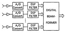
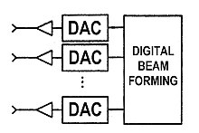
The main approach to digital signal processing in DAA is the "digital beamforming" after Analog-to-digital converters (ADC) of receiver channels or before Digital-to-analog converters (DAC) by transmission.
Digital beamforming of DAA has a big lot of advantages because in this case the digital signals massive can be transformed and combined in a few possible ways in parallel, to get different output signals. The signals from every direction can be estimated simultaneously and integrated for a longer time to increasing of signals energy when detecting far-off objects and simultaneously integrated for a shorter time to detecting fast-moving close objects.[2]
Before digital beamforming operation should be used a correction of channels characteristics by a special test source or using the heterodyne signal[3][4][5]. Such correction can be used not only for receiving channels but also in transmission channels of active DAA[6].
Limitations on the accuracy of estimation of direction of arrival signals and depth of suppression of interferences in digital antenna arrays are associated with jitter ADCs and DACs[7][8].
Maximum likelihood beamformer
In maximum likelihood beamformer (DML), the noise is modeled as a stationary Gaussian white random processes while the signal waveform as deterministic (but arbitrary) and unknown.
Bartlett beamformer
The Bartlett beamformer is a natural extension of conventional spectral analysis (spectrogram) to the DAA. Its spectral power is represented by
.

The angle that maximizes this power is an estimation of the angle of arrival.
Capon beamformer
Capon beamformer, also known as the Minimum Variance Distortionless Response (MVDR) beamforming algorithm,[9] has a power given by
.

Though the MVDR/Capon beamformer can achieve better resolution than the conventional (Bartlett) approach, but this algorithm has higher complexity due to the full-rank matrix inversion. Technical advances in GPU computing have begun to narrow this gap and make real-time Capon beamforming possible.[10]
MUSIC beamformer
MUSIC (MUltiple SIgnal Classification) beamforming algorithm starts with decomposing the covariance matrix for both the signal part and the noise part. The eigen-decomposition of is represented by
.

MUSIC uses the noise sub-space of the spatial covariance matrix in the denominator of the Capon algorithm
.

Therefore MUSIC beamformer is also known as subspace beamformer. Compared to the Capon beamformer, it gives much better DOA estimation. As an alternative approach can be used ESPRIT algorithm as well.
DAA Examples
Radars
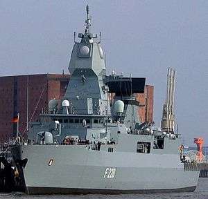 F220 Hamburg with SMART-L
 SMART-L onboard F221 Hessen
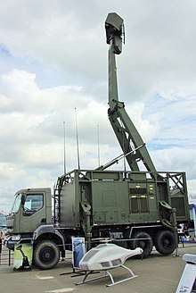 Giraffe AMB, 2007.
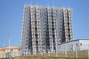 Voronezh-M radar, Lekhtusi.
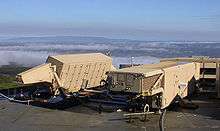
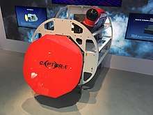 CAPTOR-E, DSEI-2019
MIMO systems
DAA use to improve the performance of radio communications in MIMO[6] (Massive MIMO) systems.
Sonars and ultrasound sensors
DAA was implemented in a big lot of sonars and medical ultrasound sensors[10].
References
- Vadym Slyusar. New Matrix Operations for DSP (Lecture). April 1999. - DOI: 10.13140/RG.2.2.31620.76164/1
- Systems Aspects of Digital Beam Forming Ubiquitous Radar, Merrill Skolnik, 2002,
- Slyusar, V. I. Correction of characteristics of receiving channels in a digital antenna array by a test source in the near zone// Radioelectronics and Communications Systems. – 2003, VOL 46; PART 1, pages 30-35.
- Slyusar, V.I. The way of correction of DAA receiving channels characteristics using the heterodyne signal// Proceedings of the III International Conference on Antenna Theory and Techniques, 8-11 September 1999, Sevastopol, pages 244 - 245.
- Slyusar, V. I., Titov I.V. Correction of smart antennas receiving channels characteristics for 4G mobile communication// Рroceedings of the IV-th International Conference on Antenna Theory and Techniques, 9-12 September 2003. Sevastopol, Pp. 374 – 375.
- Slyusar, V. I. Titov, I. V. Correction of characteristics of transmitting channels in an active digital antenna array// Radioelectronics and Communications Systems. – 2004, VOL 47; PART 8, pages 9 - 13.
- Bondarenko M.V., Slyusar V.I. "Limiting depth of jammer's suppression in a digital antenna array in conditions of ADC jitter.// 5th International Scientific Conference on Defensive Technologies, OTEH 2012. - 18 - 19 September, 2012. - Belgrade, Serbia. - Pp. 495 - 497" (PDF).
- M. Bondarenko and V.I. Slyusar. "Influence of jitter in ADC on precision of direction-finding by digital antenna arrays. // Radioelectronics and Communications Systems. - Volume 54, Number 8, 2011.- Pp. 436 - 445.-" (PDF).
- J. Capon, “High–Resolution Frequency–Wavenumber Spectrum Analysis,” Proceedings of the IEEE, 1969, Vol. 57, pp. 1408–1418
- Asen, Jon Petter; Buskenes, Jo Inge; Nilsen, Carl-Inge Colombo; Austeng, Andreas; Holm, Sverre (2014). "Implementing capon beamforming on a GPU for real-time cardiac ultrasound imaging". IEEE Transactions on Ultrasonics, Ferroelectrics, and Frequency Control. 61: 76. doi:10.1109/TUFFC.2014.6689777.
Further reading
- The estimation and tracking of frequency, Quinn and Hannan, Cambridge University Press 2001.