Liquid-propellant rocket
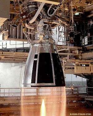
A liquid-propellant rocket or liquid rocket utilizes a rocket engine that uses liquid propellants. Liquids are desirable because they have a reasonably high density and high specific impulse (Isp). This allows the volume of the propellant tanks to be relatively low. It is also possible to use lightweight centrifugal turbopumps to pump the propellant from the tanks into the combustion chamber, which means that the propellants can be kept under low pressure. This permits the use of low-mass propellant tanks, resulting in a high mass ratio for the rocket.
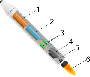
1. Liquid rocket fuel.
2. Oxidizer.
3. Pumps carry the fuel and oxidizer.
4. The combustion chamber mixes and burns the two liquids.
5. The hot exhaust is choked at the throat, which, among other things, dictates the amount of thrust produced.
6. Exhaust exits the rocket.
An inert gas stored in a tank at a high pressure is sometimes used instead of pumps in simpler small engines to force the propellants into the combustion chamber. These engines may have a lower mass ratio, but are usually more reliable, and are therefore used widely in satellites for orbit maintenance. [1]
Liquid rockets can be monopropellant rockets using a single type of propellant, or bipropellant rockets using two types of propellant. Tripropellant rockets using three types of propellant are rare. Some designs are throttleable for variable thrust operation and some may be restarted after a previous in-space shutdown. Liquid propellants are also used in hybrid rockets, with some of the advantages of a solid rocket.
History

The idea of liquid rocket as understood in the modern context first appears in the book The Exploration of Cosmic Space by Means of Reaction Devices,[2] by the Russian school teacher Konstantin Tsiolkovsky. This seminal treatise on astronautics was published in May 1903, but was not distributed outside Russia until years later, and Russian scientists paid little attention to it.[3]
The first flight of a liquid-propellant rocket took place on March 16, 1926 at Auburn, Massachusetts, when American professor Dr. Robert H. Goddard launched a vehicle using liquid oxygen and gasoline as propellants.[4] The rocket, which was dubbed "Nell", rose just 41 feet during a 2.5-second flight that ended in a cabbage field, but it was an important demonstration that rockets utilizing liquid propulsion were possible. Goddard proposed liquid propellants about fifteen years earlier and began to seriously experiment with them in 1921. The German-Romanian Hermann Oberth published a book in 1922 suggesting the use of liquid propellants.
In Germany, engineers and scientists became enthralled with liquid propulsion, building and testing them in the early 1930s in a field near Berlin.[5] This amateur rocket group, the VfR, included Wernher von Braun, who became the head of the army research station that designed the V-2 rocket weapon for the Nazis.
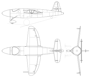
By the late 1930s, use of rocket propulsion for manned flight began to be seriously experimented with, as Germany's Heinkel He 176 made the first manned rocket-powered flight using a liquid rocket engine, designed by German aeronautics engineer Hellmuth Walter on June 20, 1939.[6] The only production rocket-powered combat aircraft ever to see military service, the Me 163 Komet in 1944-45, also used a Walter-designed liquid rocket engine, the Walter HWK 109-509, which produced up to 1,700 kgf (16.7 kN) thrust at full power.
After World War II the American government and military finally seriously considered liquid-propellant rockets as weapons and began to fund work on them. The Soviet Union did likewise, and thus began the Space Race.
Types
Liquid rockets have been built as monopropellant rockets using a single type of propellant, bipropellant rockets using two types of propellant, or more exotic tripropellant rockets using three types of propellant. Bipropellant liquid rockets generally use a liquid fuel, such as liquid hydrogen or a hydrocarbon fuel such as RP-1, and a liquid oxidizer, such as liquid oxygen. The engine may be a cryogenic rocket engine, where the fuel and oxidizer, such as hydrogen and oxygen, are gases which have been liquefied at very low temperatures.
Liquid-propellant rockets can be throttled (thrust varied) in realtime, and have control of mixture ratio (ratio at which oxidizer and fuel are mixed); they can also be shut down, and, with a suitable ignition system or self-igniting propellant, restarted.
Hybrid rockets apply a liquid or gaseous oxidizer to a solid fuel.[1] :354–356
Principle of operation
All liquid rocket engines have tankage and pipes to store and transfer propellant, an injector system, a combustion chamber which is very typically cylindrical, and one (sometimes two or more) rocket nozzles. Liquid systems enable higher specific impulse than solids and hybrid rocket motors and can provide very high tankage efficiency.
Unlike gases, a typical liquid propellant has a density similar to water, approximately 0.7–1.4g/cm³ (except liquid hydrogen which has a much lower density), while requiring only relatively modest pressure to prevent vaporization. This combination of density and low pressure permits very lightweight tankage; approximately 1% of the contents for dense propellants and around 10% for liquid hydrogen (due to its low density and the mass of the required insulation).
For injection into the combustion chamber, the propellant pressure at the injectors needs to be greater than the chamber pressure; this can be achieved with a pump. Suitable pumps usually use centrifugal turbopumps due to their high power and light weight, although reciprocating pumps have been employed in the past. Turbopumps are usually extremely lightweight and can give excellent performance; with an on-Earth weight well under 1% of the thrust. Indeed, overall rocket engine thrust to weight ratios including a turbopump have been as high as 155:1 with the SpaceX Merlin 1D rocket engine and up to 180:1 with the vacuum version [7]
Alternatively, instead of pumps, a heavy tank of a high-pressure inert gas such as helium can be used, and the pump forgone; but the delta-v that the stage can achieve is often much lower due to the extra mass of the tankage, reducing performance; but for high altitude or vacuum use the tankage mass can be acceptable.
The major components of a rocket engine are therefore the combustion chamber (thrust chamber), pyrotechnic igniter, propellant feed system, valves, regulators, the propellant tanks, and the rocket engine nozzle. In terms of feeding propellants to the combustion chamber, liquid-propellant engines are either pressure-fed or pump-fed, and pump-fed engines work in either a gas-generator cycle, a staged-combustion cycle, or an expander cycle.
A liquid rocket engine can be tested prior to use, whereas for a solid rocket motor a rigorous quality management must be applied during manufacturing to ensure high reliability.[8] A Liquid rocket engine can also usually be reused for several flights, as in the Space Shuttle and Falcon 9 series rockets, although reuse of solid rocket motors was also effectively demonstrated during the shuttle program.
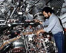
Use of liquid propellants can be associated with a number of issues:
- Because the propellant is a very large proportion of the mass of the vehicle, the center of mass shifts significantly rearward as the propellant is used; one will typically lose control of the vehicle if its center mass gets too close to the center of drag/pressure.
- When operated within an atmosphere, pressurization of the typically very thin-walled propellant tanks must guarantee positive gauge pressure at all times to avoid catastrophic collapse of the tank.
- Liquid propellants are subject to slosh, which has frequently led to loss of control of the vehicle. This can be controlled with slosh baffles in the tanks as well as judicious control laws in the guidance system.
- They can suffer from pogo oscillation where the rocket suffers from uncommanded cycles of acceleration.
- Liquid propellants often need ullage motors in zero-gravity or during staging to avoid sucking gas into engines at start up. They are also subject to vortexing within the tank, particularly towards the end of the burn, which can also result in gas being sucked into the engine or pump.
- Liquid propellants can leak, especially hydrogen, possibly leading to the formation of an explosive mixture.
- Turbopumps to pump liquid propellants are complex to design, and can suffer serious failure modes, such as overspeeding if they run dry or shedding fragments at high speed if metal particles from the manufacturing process enter the pump.
- Cryogenic propellants, such as liquid oxygen, freeze atmospheric water vapor into ice. This can damage or block seals and valves and can cause leaks and other failures. Avoiding this problem often requires lengthy chilldown procedures which attempt to remove as much of the vapor from the system as possible. Ice can also form on the outside of the tank, and later fall and damage the vehicle. External foam insulation can cause issues as shown by the Space Shuttle Columbia disaster. Non-cryogenic propellants do not cause such problems.
- Non-storable liquid rockets require considerable preparation immediately before launch. This makes them less practical than solid rockets for most weapon systems.
Propellants
Thousands of combinations of fuels and oxidizers have been tried over the years. Some of the more common and practical ones are:
Cryogenic
- Liquid oxygen (LOX, O2) and liquid hydrogen (LH2, H2) – Space Shuttle main engines, Ariane 5 main stage and the Ariane 5 ECA second stage, the BE-3 of Blue Origin's New Shepard, the first and second stage of the Delta IV, the upper stages of the Ares I, Saturn V's second and third stages, Saturn IB, and Saturn I as well as Centaur rocket stage, the first stage and second stage of the H-II, H-IIA, H-IIB, and the upper stage of the GSLV Mk-II and GSLV Mk-III. The main advantages of this mixture are a clean burn (water vapor is the only combustion product) and high performance. [9]
- Liquid oxygen (LOX) and liquid methane (CH4, Liquefied natural gas, LNG) – the in-development Raptor (SpaceX) and BE-4 (Blue Origin) engines. (See also Propulsion Cryogenics & Advanced Development project of NASA, and Project Morpheus.)
One of the most efficient mixtures, oxygen and hydrogen, suffers from the extremely low temperatures required for storing liquid hydrogen (around 20 K or −253.2 °C or −423.7 °F) and very low fuel density (70 kg/m3 or 4.4 lb/cu ft, compared to RP-1 at 820 kg/m3 or 51 lb/cu ft), necessitating large tanks that must also be lightweight and insulating. Lightweight foam insulation on the Space Shuttle external tank led to the Space Shuttle Columbia's destruction, as a piece broke loose, damaged its wing and caused it to break up on atmospheric reentry.
Liquid methane/LNG has several advantages over LH2. Its performance (max. specific impulse) is lower than that of LH2 but higher than that of RP1 (Kerosene) and solid propellants, and its higher density provides higher thrust to volume ratios than LH2, similar to other hydrocarbon fuels such as RP1. This makes it specially attractive for reusable launch systems because higher density allows for smaller motors, propellant tanks and associated systems. [10] LNG is less expensive, being readily available in large quantities. It can be stored for more prolonged periods of time, and is less explosive than LH2.
Semi-cryogenic
- Liquid oxygen (LOX) and RP-1 – Saturn V's first stage, Zenit rocket, R-7-derived vehicles including Soyuz, Delta, Saturn I, and Saturn IB first stages, Titan I and Atlas rockets, Falcon 1 and Falcon 9
- Liquid oxygen (LOX) and alcohol (ethanol, C2H5OH) – early liquid rockets, like German (World War II) A4, aka V-2, and Redstone
- Liquid oxygen (LOX) and gasoline – Robert Goddard's first liquid rocket
- Liquid oxygen (LOX) and carbon monoxide (CO) – proposed for a Mars hopper vehicle (with a specific impulse of approximately 250 s), principally because carbon monoxide and oxygen can be straightforwardly produced by Zirconia electrolysis from the Martian atmosphere without requiring use of any of the Martian water resources to obtain Hydrogen.[11]
Non-cryogenic/storable/hypergolic
Many non-cryogenic bipropellants are hypergolic (self igniting).
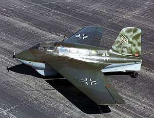
- T-Stoff (80% hydrogen peroxide, H2O2 as the oxidizer) and C-Stoff (methanol, CH3OH, and hydrazine hydrate, N2H4•n(H2O) as the fuel) – used for the Hellmuth-Walter-Werke HWK 109-509A, -B and -C engine family used on the Messerschmitt Me 163B Komet, an operational rocket fighter plane of World War II, and Ba 349 Natter manned VTO interceptor prototypes.
- Nitric acid (HNO3) and kerosene – Soviet BI-1 and MiG I-270 rocket fighter prototypes, Scud-A, aka SS-1 SRBM
- Inhibited red fuming nitric acid (IRFNA, HNO3 + N2O4) and unsymmetric dimethyl hydrazine (UDMH, (CH3)2N2H2) – Soviet Scud-C, aka SS-1-c,-d,-e
- Nitric acid 73% with dinitrogen tetroxide 27% (AK27) and kerosene/gasoline mixture (TM-185) – various Russian (USSR) cold-war ballistic missiles (R-12, Scud-B,-D), Iran: Shahab-5, North Korea: Taepodong-2
- High-test peroxide (H2O2) and kerosene – UK (1970s) Black Arrow, USA Development (or study): BA-3200
- Hydrazine (N2H4) and red fuming nitric acid – MIM-3 Nike Ajax Antiaircraft Rocket
- Unsymmetric dimethylhydrazine (UDMH) and dinitrogen tetroxide (N2O4) – Proton, Rokot, Long March 2 (used to launch Shenzhou crew vehicles.)
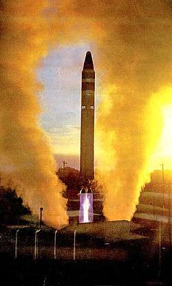 Titan II
- Aerozine 50 (50% UDMH, 50% hydrazine) and dinitrogen tetroxide (N2O4) – Titans 2–4, Apollo lunar module, Apollo service module, interplanatary probes (Such as Voyager 1 and Voyager 2)
- Monomethylhydrazine (MMH, (CH3)HN2H2) and dinitrogen tetroxide (N2O4) – Space Shuttle orbiter's Orbital maneuvering system (OMS) engines and Reaction control system (RCS) thrusters. SpaceX's Draco and SuperDraco engines for the Dragon spacecraft.
For storable ICBMs and most spacecraft, including crewed vehicles, planetary probes, and satellites, storing cryogenic propellants over extended periods is unfeasible. Because of this, mixtures of hydrazine or its derivatives in combination with nitrogen oxides are generally used for such applications, but are toxic and carcinogenic. Consequently, to improve handling, some crew vehicles such as Dream Chaser and Space Ship Two plan to use hybrid rockets with non-toxic fuel and oxidizer combinations.
Injectors
The injector implementation in liquid rockets determines the percentage of the theoretical performance of the nozzle that can be achieved. A poor injector performance causes unburnt propellant to leave the engine, giving poor efficiency.
Additionally, injectors are also usually key in reducing thermal loads on the nozzle; by increasing the proportion of fuel around the edge of the chamber, this gives much lower temperatures on the walls of the nozzle.
Types of injectors
Injectors can be as simple as a number of small diameter holes arranged in carefully constructed patterns through which the fuel and oxidizer travel. The speed of the flow is determined by the square root of the pressure drop across the injectors, the shape of the hole and other details such as the density of the propellant.
The first injectors used on the V-2 created parallel jets of fuel and oxidizer which then combusted in the chamber. This gave quite poor efficiency.
Injectors today classically consist of a number of small holes which aim jets of fuel and oxidizer so that they collide at a point in space a short distance away from the injector plate. This helps to break the flow up into small droplets that burn more easily.
The main types of injectors are
- Shower head
- Self-impinging doublet
- Cross-impinging triplet
- Centripetal or swirling
- Pintle
The pintle injector permits good mixture control of fuel and oxidizer over a wide range of flow rates. The pintle injector was used in the Apollo Lunar Module engines (Descent Propulsion System) and the Kestrel engine, it is currently used in the Merlin engine on Falcon 9 and Falcon Heavy rockets.
The RS-25 engine designed for the Space Shuttle uses a system of fluted posts, which use heated hydrogen from the preburner to vaporize the liquid oxygen flowing through the center of the posts[12] and this improves the rate and stability of the combustion process; previous engines such as the F-1 used for the Apollo program had significant issues with oscillations that led to destruction of the engines, but this was not a problem in the RS-25 due to this design detail.
Valentin Glushko invented the centripetal injector in the early 1930s, and it has been almost universally used in Russian engines. Rotational motion is applied to the liquid (and sometimes the two propellants are mixed), then it is expelled through a small hole, where it forms a cone-shaped sheet that rapidly atomizes. Goddard's first liquid engine used a single impinging injector. German scientists in WWII experimented with impinging injectors on flat plates, used successfully in the Wasserfall missile.
Combustion stability
To avoid instabilities such as chugging, which is a relatively low speed oscillation, the engine must be designed with enough pressure drop across the injectors to render the flow largely independent of the chamber pressure. This pressure drop is normally achieved by using at least 20% of the chamber pressure across the injectors.
Nevertheless, particularly in larger engines, a high speed combustion oscillation is easily triggered, and these are not well understood. These high speed oscillations tend to disrupt the gas side boundary layer of the engine, and this can cause the cooling system to rapidly fail, destroying the engine. These kinds of oscillations are much more common on large engines, and plagued the development of the Saturn V, but were finally overcome.
Some combustion chambers, such as those of the RS-25 engine, use Helmholtz resonators as damping mechanisms to stop particular resonant frequencies from growing.
To prevent these issues the RS-25 injector design instead went to a lot of effort to vaporise the propellant prior to injection into the combustion chamber. Although many other features were used to ensure that instabilities could not occur, later research showed that these other features were unnecessary, and the gas phase combustion worked reliably.
Testing for stability often involves the use of small explosives. These are detonated within the chamber during operation, and causes an impulsive excitation. By examining the pressure trace of the chamber to determine how quickly the effects of the disturbance die away, it is possible to estimate the stability and redesign features of the chamber if required.
Engine cycles
For liquid-propellant rockets, four different ways of powering the injection of the propellant into the chamber are in common use.[13]
Fuel and oxidizer must be pumped into the combustion chamber against the pressure of the hot gasses being burned, and engine power is limited by the rate at which propellant can be pumped into the combustion chamber. For atmospheric or launcher use, high pressure, and thus high power, engine cycles are desirable to minimize gravity drag. For orbital use, lower power cycles are usually fine.
- Pressure-fed cycle
- The propellants are forced in from pressurised (relatively heavy) tanks. The heavy tanks mean that a relatively low pressure is optimal, limiting engine power, but all the fuel is burned, allowing high efficiency. The pressurant used is frequently helium due to its lack of reactivity and low density. Examples: AJ-10, used in the Space Shuttle OMS, Apollo SPS, and the second stage of the Delta II.
- Electric pump-fed
- It uses an electric motor, generally a brushless DC electric motor, to drive the pumps. The electric motor is powered by a battery pack. It is relatively simple to implement and reduces the complexity of the turbomachinery design, but at the expense of the extra dry mass of the battery pack. Example engine is the Rutherford.
- Gas-generator cycle
- A small percentage of the propellants are burnt in a preburner to power a turbopump and then exhausted through a separate nozzle, or low down on the main one. This results in a reduction in efficiency since the exhaust contributes little or no thrust, but the pump turbines can be very large, allowing for high power engines. Examples: Saturn V's F-1 and J-2, Delta IV's RS-68, Ariane 5's HM7B, Falcon 9's Merlin.
- Tap-off cycle
- Takes hot gases from the main combustion chamber of the rocket engine and routes them through engine turbopump turbines to pump propellant, then is exhausted. Since not all propellant flows through the main combustion chamber, the tap-off cycle is considered an open-cycle engine. Examples include the J-2S and BE-3.
- Expander cycle
- Cryogenic fuel (hydrogen, or methane) is used to cool the walls of the combustion chamber and nozzle. Absorbed heat vaporizes and expands the fuel which is then used to drive the turbopumps before it enters the combustion chamber, allowing for high efficiency, or is bled overboard, allowing for higher power turbopumps. The limited heat available to vaporize the fuel constrains engine power. Examples: RL10 for Atlas V and Delta IV second stages (closed cycle), H-II's LE-5 (bleed cycle).
- Staged combustion cycle
- A fuel- or oxidizer-rich mixture is burned in a preburner and then drives turbopumps, and this high-pressure exhaust is fed directly into the main chamber where the remainder of the fuel or oxidizer undergoes combustion, permitting very high pressures and efficiency. Examples: SSME, RD-191, LE-7.
Engine cycle tradeoffs
Selecting an engine cycle is one of the earlier steps to rocket engine design. A number of tradeoffs arise from this selection, some of which include:
| Cycle type | ||||
|---|---|---|---|---|
| Gas generator | Expander cycle | Staged-combustion | Pressure-fed | |
| Advantages | Simple; low dry mass; allows for high power turbopumps for high thrust | High specific impulse; fairly low complexity | High specific impulse; high combustion chamber pressures allowing for high thrust | Simple; no turbopumps; low dry mass; high specific impulse |
| Disadvantages | Lower specific impulse | Must use cryogenic fuel; heat transfer to the fuel limits available power to the turbine and thus engine thrust | Greatly increased complexity | Tank pressure limits combustion chamber pressure and thrust; heavy tanks and associated pressurization hardware |
Cooling
Injectors are commonly laid out so that a fuel-rich layer is created at the combustion chamber wall. This reduces the temperature there, and downstream to the throat and even into the nozzle and permits the combustion chamber to be run at higher pressure, which permits a higher expansion ratio nozzle to be used which gives a higher ISP and better system performance.[14] A liquid rocket engine often employs regenerative cooling, which uses the fuel or less commonly the oxidizer to cool the chamber and nozzle.
Ignition
Ignition can be performed in many ways, but perhaps more so with liquid propellants than other rockets a consistent and significant ignitions source is required; a delay of ignition (in some cases as small as) a few tens of milliseconds can cause over-pressure of the chamber due to excess propellant. A hard start can even cause an engine to explode.
Generally, ignition systems try to apply flames across the injector surface, with a mass flow of approximately 1% of the full mass flow of the chamber.
Safety interlocks are sometimes used to ensure the presence of an ignition source before the main valves open; however reliability of the interlocks can in some cases be lower than the ignition system. Thus it depends on whether the system must fail safe, or whether overall mission success is more important. Interlocks are rarely used for upper, unmanned stages where failure of the interlock would cause loss of mission, but are present on the RS-25 engine, to shut the engines down prior to liftoff of the Space Shuttle. In addition, detection of successful ignition of the igniter is surprisingly difficult, some systems use thin wires that are cut by the flames, pressure sensors have also seen some use.
Methods of ignition include pyrotechnic, electrical (spark or hot wire), and chemical. Hypergolic propellants have the advantage of self igniting, reliably and with less chance of hard starts. In the 1940s, the Russians began to start engines with hypergols, then switch over to the primary propellants after ignition. This was also used on the American F-1 rocket engine on the Apollo program.
Ignition with a Pyrophoric Agent - Triethylaluminium ignites on contact with air and will ignite and/or decompose on contact with water, and with any other oxidizer—it is one of the few substances sufficiently pyrophoric to ignite on contact with cryogenic liquid oxygen. The enthalpy of combustion, ΔcH°, is −5,105.70 ± 2.90 kJ/mol (−1,220.29 ± 0.69 kcal/mol). Its easy ignition makes it particularly desirable as a rocket engine ignitor. May be used in conjunction with Triethylborane to create triethylaluminum-triethylborane, better known as TEA-TEB.
See also
- Comparison of orbital launch systems
- Comparison of orbital launchers families
- Comparison of orbital rocket engines
- Comparison of solid-fuelled orbital launch systems
- List of space launch system designs
- List of missiles
- List of orbital launch systems
- List of sounding rockets
- List of military rockets
References
- Sutton, George P. (1963). Rocket Propulsion Elements, 3rd edition. New York: John Wiley & Sons. p. 25, 186, 187.
- Russian title Issledovaniye mirovykh prostranstv reaktivnymi priborami (Исследование мировых пространств реактивными приборами)
- Thirupathi, M.; Madhavi, N.; Naidu, K.Simhachalam (June 2015). "Design and Analysis of a Fuel Injector of a Liquid Rocket Engine" (PDF). International Journal of Engineering and Advanced Technology (IJEAT). 4 (5): 223.
- "Re-Creating History". NASA. Archived from the original on 2007-12-01.
- Magazines, Hearst (1 May 1931). Popular Mechanics. Hearst Magazines. p. 716 – via Internet Archive.
Popular Mechanics 1931 curtiss.
- Volker Koos, Heinkel He 176 – Dichtung und Wahrheit, Jet&Prop 1/94 p. 17–21
- "Thomas Mueller's answer to Is SpaceX's Merlin 1D's thrust-to-weight ratio of 150+ believable? - Quora". www.quora.com.
- NASA:Liquid rocket engines, 1998, Purdue University
- https://global.jaxa.jp/projects/engineering/components/lng/index.html
- https://global.jaxa.jp/projects/engineering/components/lng/index.html
- Landis (2001). "Mars Rocket Vehicle Using In Situ Propellants". Journal of Spacecraft and Rockets. 38 (5): 730–735. Bibcode:2001JSpRo..38..730L. doi:10.2514/2.3739.
- Sutton, George P. and Biblarz, Oscar, Rocket Propulsion Elements, 7th ed., John Wiley & Sons, Inc., New York, 2001.
- "Sometimes, Smaller is Better". Archived from the original on 2012-04-14. Retrieved 2010-06-01.
- Rocket Propulsion elements - Sutton Biblarz, section 8.1
