Photolithography
Photolithography, also called optical lithography or UV lithography, is a process used in microfabrication to pattern parts on a thin film or the bulk of a substrate (also called a wafer). It uses light to transfer a geometric pattern from a photomask (also called an optical mask) to a photosensitive (that is, light-sensitive) chemical photoresist on the substrate. A series of chemical treatments then either etches the exposure pattern into the material or enables deposition of a new material in the desired pattern upon the material underneath the photoresist. In complex integrated circuits, a CMOS wafer may go through the photolithographic cycle as many as 50 times.
Photolithography shares some fundamental principles with photography in that the pattern in the photoresist etching is created by exposing it to light, either directly (without using a mask) or with a projected image using a photomask. This procedure is comparable to a high precision version of the method used to make printed circuit boards. Subsequent stages in the process have more in common with etching than with lithographic printing. This method can create extremely small patterns, down to a few tens of nanometers in size. It provides precise control of the shape and size of the objects it creates and can create patterns over an entire surface cost-effectively. Its main disadvantages are that it requires a flat substrate to start with, it is not very effective at creating shapes that are not flat, and it can require extremely clean operating conditions. Photolithography is the standard method of printed circuit board (PCB) and microprocessor fabrication. Directed self-assembly is being evaluated as an alternative to photolithography.[1]
History
The root words photo, litho, and graphy all have Greek origins, with the meanings 'light', 'stone' and 'writing' respectively. As suggested by the name compounded from them, photolithography is a printing method (originally based on the use of limestone printing plates) in which light plays an essential role. In the 1820s, Nicephore Niepce invented a photographic process that used Bitumen of Judea, a natural asphalt, as the first photoresist. A thin coating of the bitumen on a sheet of metal, glass or stone became less soluble where it was exposed to light; the unexposed parts could then be rinsed away with a suitable solvent, baring the material beneath, which was then chemically etched in an acid bath to produce a printing plate. The light-sensitivity of bitumen was very poor and very long exposures were required, but despite the later introduction of more sensitive alternatives, its low cost and superb resistance to strong acids prolonged its commercial life into the early 20th century. In 1940, Oskar Süß created a positive photoresist by using diazonaphthoquinone, which worked in the opposite manner: the coating was initially insoluble and was rendered soluble where it was exposed to light.[2] In 1954, Louis Plambeck Jr. developed the Dycryl polymeric letterpress plate, which made the platemaking process faster.[3]
In 1952, the U.S. military assigned Jay W. Lathrop and James R. Nall at the National Bureau of Standards (later the U.S. Army Diamond Ordnance Fuze Laboratory, which eventually merged to form the now-present Army Research Laboratory) with the task of finding a way to reduce the size of electronic circuits in order to better fit the necessary circuitry in the limited space available inside a proximity fuze.[4] Inspired by the application of photoresist, a photosensitive liquid used to mark the boundaries of rivet holes in metal aircraft wings, Nall determined that a similar process can be used to protect the germanium in the transistors and even pattern the surface with light.[5] During development, Lathrop and Nall were successful in creating a 2D miniaturized hybrid integrated circuit with transistors using this technique.[4] In 1958, during the IRE Professional Group on Electron Devices (PGED) conference in Washington, D.C., they presented the first paper to describe the fabrication of transistors using photographic techniques and adopted the term "photolithography" to describe the process, marking the first published use of the term to describe semiconductor device patterning.[5][6]
Despite the fact that photolithography of electronic components concerns etching metal duplicates, rather than etching stone to produce a "master" as in conventional lithographic printing, Lathrop and Nall chose the term "photolithography" over "photoetching" because the former sounded "high tech."[4] A year after the conference, Lathrop and Nall's patent on photolithography was formally approved on June 9, 1959.[7] Photolithography would later contribute to the development of the first semiconductor ICs as well as the first microchips.[4]
Basic procedure

A single iteration of photolithography combines several steps in sequence. Modern cleanrooms use automated, robotic wafer track systems to coordinate the process. The procedure described here omits some advanced treatments, such as thinning agents or edge-bead removal.[8] The Photolithography process is carried out by the wafer track and stepper/scanner, and the wafer track system and the stepper/scanner are installed side by side.
Cleaning
If organic or inorganic contaminations are present on the wafer surface, they are usually removed by wet chemical treatment, e.g. the RCA clean procedure based on solutions containing hydrogen peroxide. Other solutions made with trichloroethylene, acetone or methanol can also be used to clean.[9]
Preparation
The wafer is initially heated to a temperature sufficient to drive off any moisture that may be present on the wafer surface; 150 °C for ten minutes is sufficient. Wafers that have been in storage must be chemically cleaned to remove contamination. A liquid or gaseous "adhesion promoter", such as Bis(trimethylsilyl)amine ("hexamethyldisilazane", HMDS), is applied to promote adhesion of the photoresist to the wafer. The surface layer of silicon dioxide on the wafer reacts with HMDS to form tri-methylated silicon-dioxide, a highly water repellent layer not unlike the layer of wax on a car's paint. This water repellent layer prevents the aqueous developer from penetrating between the photoresist layer and the wafer's surface, thus preventing so-called lifting of small photoresist structures in the (developing) pattern. In order to ensure the development of the image, it is best covered and placed over a hot plate and let it dry while stabilizing the temperature at 120 °C.[10]
Photoresist application
The wafer is covered with photoresist by spin coating. Thus, the top layer of resist is quickly ejected from the wafer's edge while the bottom layer still creeps slowly radially along the wafer. In this way, any 'bump' or 'ridge' of resist is removed, leaving a very flat layer. Final thickness is also determined by the evaporation of liquid solvents from the resist. For very small, dense features (< 125 or so nm), lower resist thicknesses (< 0.5 microns) are needed to overcome collapse effects at high aspect ratios; typical aspect ratios are < 4:1.
The photoresist-coated wafer is then prebaked to drive off excess photoresist solvent, typically at 90 to 100 °C for 30 to 60 seconds on a hotplate. A BARC coating (Bottom Anti-Reflectant Coating) may be applied before the photoresist is applied, to avoid refections from occurring under the photoresist and to improve the photoresist's performance at smaller semiconductor nodes.[11][12][13]
Exposure and developing
After prebaking, the photoresist is exposed to a pattern of intense light. The exposure to light causes a chemical change that allows some of the photoresist to be removed by a special solution, called "developer" by analogy with photographic developer. Positive photoresist, the most common type, becomes soluble in the developer when exposed; with negative photoresist, unexposed regions are soluble in the developer.
A post-exposure bake (PEB) is performed before developing, typically to help reduce standing wave phenomena caused by the destructive and constructive interference patterns of the incident light. In deep ultraviolet lithography, chemically amplified resist (CAR) chemistry is used. This process is much more sensitive to PEB time, temperature, and delay, as most of the "exposure" reaction (creating acid, making the polymer soluble in the basic developer) actually occurs in the PEB.[14]
The develop chemistry is delivered on a spinner, much like photoresist. Developers originally often contained sodium hydroxide (NaOH). However, sodium is considered an extremely undesirable contaminant in MOSFET fabrication because it degrades the insulating properties of gate oxides (specifically, sodium ions can migrate in and out of the gate, changing the threshold voltage of the transistor and making it harder or easier to turn the transistor on over time). Metal-ion-free developers such as tetramethylammonium hydroxide (TMAH) are now used.
The resulting wafer is then "hard-baked" if a non-chemically amplified resist was used, typically at 120 to 180 °C[15] for 20 to 30 minutes. The hard bake solidifies the remaining photoresist, to make a more durable protecting layer in future ion implantation, wet chemical etching, or plasma etching.
From preparation until this step, the photolithography procedure has been carried out by two machines: the photolithography stepper or scanner, and the coater/developer. The two machines are usually installed side by side.
Etching
In etching, a liquid ("wet") or plasma ("dry") chemical agent removes the uppermost layer of the substrate in the areas that are not protected by photoresist. In semiconductor fabrication, dry etching techniques are generally used, as they can be made anisotropic, in order to avoid significant undercutting of the photoresist pattern. This is essential when the width of the features to be defined is similar to or less than the thickness of the material being etched (i.e. when the aspect ratio approaches unity). Wet etch processes are generally isotropic in nature, which is often indispensable for microelectromechanical systems, where suspended structures must be "released" from the underlying layer.
The development of low-defectivity anisotropic dry-etch process has enabled the ever-smaller features defined photolithographically in the resist to be transferred to the substrate material.
Photoresist removal
After a photoresist is no longer needed, it must be removed from the substrate. This usually requires a liquid "resist stripper", which chemically alters the resist so that it no longer adheres to the substrate. Alternatively, photoresist may be removed by a plasma containing oxygen, which oxidizes it. This process is called ashing, and resembles dry etching. Use of 1-Methyl-2-pyrrolidone (NMP) solvent for photoresist is another method used to remove an image. When the resist has been dissolved, the solvent can be removed by heating to 80 °C without leaving any residue.[16]
Exposure ("printing") systems
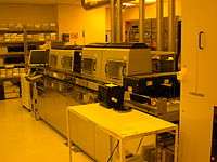
Exposure systems typically produce an image on the wafer using a photomask. The photomask blocks light in some areas and lets it pass in others. (Maskless lithography projects a precise beam directly onto the wafer without using a mask, but it is not widely used in commercial processes.) Exposure systems may be classified by the optics that transfer the image from the mask to the wafer.
Photolithography produces better thin film transistor structures than printed electronics, due to smoother printed layers, less wavy patterns, and more accurate drain-source electrode registration.[17]
Contact and proximity
A contact printer, the simplest exposure system, puts a photomask in direct contact with the wafer and exposes it to a uniform light. A proximity printer puts a small gap between the photomask and wafer. In both cases, the mask covers the entire wafer, and simultaneously patterns every die.
Contact printing is liable to damage both the mask and the wafer, and this was the primary reason it was abandoned for high volume production. Both contact and proximity lithography require the light intensity to be uniform across an entire wafer, and the mask to align precisely to features already on the wafer. As modern processes use increasingly large wafers, these conditions become increasingly difficult.
Research and prototyping processes often use contact or proximity lithography, because it uses inexpensive hardware and can achieve high optical resolution. The resolution in proximity lithography is approximately the square root of the product of the wavelength and the gap distance. Hence, except for projection lithography (see below), contact printing offers the best resolution, because its gap distance is approximately zero (neglecting the thickness of the photoresist itself). In addition, nanoimprint lithography may revive interest in this familiar technique, especially since the cost of ownership is expected to be low; however, the shortcomings of contact printing discussed above remain as challenges.
Projection
Very-large-scale integration (VLSI) lithography uses projection systems. Unlike contact or proximity masks, which cover an entire wafer, projection masks (known as "reticles") show only one die or an array of dies (known as a "field"). Projection exposure systems (steppers or scanners) project the mask onto the wafer many times to create the complete pattern. The difference between steppers and scanners is that, during exposure, a scanner moves the photomask and the wafer simultaneously, while a stepper only moves the wafer. A mask aligner does not move the photomask nor the wafer during exposure. Immersion lithography scanners use a layer of Ultrapure water between the lens and the wafer to increase resolution. An alternative to photolithography is nanoimprint lithography.
Photomasks
The image for the mask originates from a computerized data file. This data file is converted to a series of polygons and written onto a square of fused quartz substrate covered with a layer of chromium using a photolithographic process. A laser beam (laser writer) or a beam of electrons (e-beam writer) is used to expose the pattern defined by the data file and travels over the surface of the substrate in either a vector or raster scan manner. Where the photoresist on the mask is exposed, the chrome can be etched away, leaving a clear path for the illumination light in the stepper/scanner system to travel through.
Resolution in projection systems
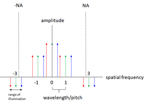
The ability to project a clear image of a small feature onto the wafer is limited by the wavelength of the light that is used, and the ability of the reduction lens system to capture enough diffraction orders from the illuminated mask. Current state-of-the-art photolithography tools use deep ultraviolet (DUV) light from excimer lasers with wavelengths of 248 and 193 nm (the dominant lithography technology today is thus also called "excimer laser lithography"), which allow minimum feature sizes down to 50 nm. Excimer laser lithography has thus played a critical role in the continued advance of the Moore's Law for the last 20 years (see below[18]).
The minimum feature size that a projection system can print is given approximately by:
where
is the minimum feature size (also called the critical dimension, target design rule). It is also common to write 2 times the half-pitch.
(commonly called k1 factor) is a coefficient that encapsulates process-related factors, and typically equals 0.4 for production. The minimum feature size can be reduced by decreasing this coefficient through computational lithography.
is the wavelength of light used
is the numerical aperture of the lens as seen from the wafer
According to this equation, minimum feature sizes can be decreased by decreasing the wavelength, and increasing the numerical aperture (to achieve a tighter focused beam and a smaller spot size). However, this design method runs into a competing constraint. In modern systems, the depth of focus is also a concern:
Here, is another process-related coefficient. The depth of focus restricts the thickness of the photoresist and the depth of the topography on the wafer. Chemical mechanical polishing is often used to flatten topography before high-resolution lithographic steps.
Stochastic effects
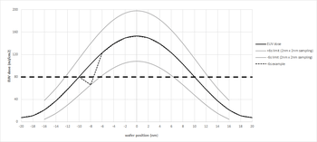
As light consists of photons, at low doses the image quality ultimately depends on the photon number. This affects the use of extreme ultraviolet lithography or EUVL, which is limited to the use of low doses on the order of 20 photons/nm2.[19] This is due to fewer photons for the same energy dose for a shorter wavelength (higher energy per photon).
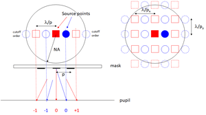
The stochastic effects would become more complicated with larger pitch patterns with more diffraction orders and using more illumination source points.[20][21]
Light sources
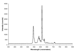
Historically, photolithography has used ultraviolet light from gas-discharge lamps using mercury, sometimes in combination with noble gases such as xenon. These lamps produce light across a broad spectrum with several strong peaks in the ultraviolet range. This spectrum is filtered to select a single spectral line. From the early 1960s through the mid-1980s, Hg lamps had been used in lithography for their spectral lines at 436 nm ("g-line"), 405 nm ("h-line") and 365 nm ("i-line"). However, with the semiconductor industry's need for both higher resolution (to produce denser and faster chips) and higher throughput (for lower costs), the lamp-based lithography tools were no longer able to meet the industry's high-end requirements.
This challenge was overcome when in a pioneering development in 1982, excimer laser lithography was proposed and demonstrated at I.B.M. by Kanti Jain,[22][23][24][25] and now excimer laser lithography machines (steppers and scanners) are the primary tools used worldwide in microelectronics production. With the rapid advances made in tool technology in the last two decades, it is the semiconductor industry view[18] that excimer laser lithography has been a crucial factor in the continued advance of Moore's Law, enabling minimum features sizes in chip manufacturing to shrink from 800 nanometers in 1990 to 7 nanometers in 2018.[26][27] From an even broader scientific and technological perspective, in the 50-year history of the laser since its first demonstration in 1960, the invention and development of excimer laser lithography has been recognized as a major milestone.[28][29][30]
The commonly used deep ultraviolet excimer lasers in lithography systems are the krypton fluoride laser at 248 nm wavelength and the argon fluoride laser at 193 nm wavelength. The primary manufacturers of excimer laser light sources in the 1980s were Lambda Physik (now part of Coherent, Inc.) and Lumonics. Since the mid-1990s Cymer Inc. has become the dominant supplier of excimer laser sources to the lithography equipment manufacturers, with Gigaphoton Inc. as their closest rival. Generally, an excimer laser is designed to operate with a specific gas mixture; therefore, changing wavelength is not a trivial matter, as the method of generating the new wavelength is completely different, and the absorption characteristics of materials change. For example, air begins to absorb significantly around the 193 nm wavelength; moving to sub-193 nm wavelengths would require installing vacuum pump and purge equipment on the lithography tools (a significant challenge). An inert gas atmosphere can sometimes be used as a substitute for a vacuum, to avoid the need for hard plumbing. Furthermore, insulating materials such as silicon dioxide, when exposed to photons with energy greater than the band gap, release free electrons and holes which subsequently cause adverse charging.
Optical lithography has been extended to feature sizes below 50 nm using the 193 nm ArF excimer laser and liquid immersion techniques. Also termed immersion lithography, this enables the use of optics with numerical apertures exceeding 1.0. The liquid used is typically ultra-pure, deionised water, which provides for a refractive index above that of the usual air gap between the lens and the wafer surface. The water is continually circulated to eliminate thermally-induced distortions. Water will only allow NA's of up to ~1.4, but fluids with higher refractive indices would allow the effective NA to be increased further.
Experimental tools using the 157 nm wavelength from the F2 excimer laser in a manner similar to current exposure systems have been built. These were once targeted to succeed 193 nm lithography at the 65 nm feature size node but have now all but been eliminated by the introduction of immersion lithography. This was due to persistent technical problems with the 157 nm technology and economic considerations that provided strong incentives for the continued use of 193 nm excimer laser lithography technology. High-index immersion lithography is the newest extension of 193 nm lithography to be considered. In 2006, features less than 30 nm were demonstrated by IBM using this technique.[31]
UV excimer lasers have been demonstrated to about 126 nm (for Ar2*). Mercury arc lamps are designed to maintain a steady DC current of 50 to 150 Volts, however excimer lasers have a higher resolution. Excimer lasers are gas-based light systems that are usually filled with inert and halide gases (Kr, Ar, Xe, F and Cl) that are charged by an electric field. The higher the frequency, the greater the resolution of the image. KrF lasers are able to function at a frequency of 4 kHz . In addition to running at a higher frequency, excimer lasers are compatible with more advanced machines than mercury arc lamps are. They are also able to operate from greater distances (up to 25 meters) and are able to maintain their accuracy with a series of mirrors and antireflective-coated lenses. By setting up multiple lasers and mirrors, the amount of energy loss is minimized, also since the lenses are coated with antireflective material, the light intensity remains relatively the same from when it left the laser to when it hits the wafer.[32]
Lasers have been used to indirectly generate non-coherent extreme UV (EUV) light at 13.5 nm for extreme ultraviolet lithography. The EUV light is not emitted by the laser, but rather by a tin or xenon plasma which is excited by an excimer laser. Fabrication of feature sizes of 10 nm has been demonstrated in production environments, but not yet at rates needed for commercialization. However, this is expected by 2016.[33] This technique does not require a synchrotron, and EUV sources, as noted, do not produce coherent light. However vacuum systems and a number of novel technologies (including much higher EUV energies than are now produced) are needed to work with UV at the edge of the X-ray spectrum (which begins at 10 nm).
Theoretically, an alternative light source for photolithography, especially if and when wavelengths continue to decrease to extreme UV or X-ray, is the free-electron laser (or one might say xaser for an X-ray device). Free-electron lasers can produce high quality beams at arbitrary wavelengths.
Visible and infrared femtosecond lasers were also applied for lithography. In that case photochemical reactions are initiated by multiphoton absorption. Usage of these light sources have a lot of benefits, including possibility to manufacture true 3D objects and process non-photosensitized (pure) glass-like materials with superb optical resiliency.[34]
Experimental methods
Photolithography has been defeating predictions of its demise for many years. For instance, by the early 1980s, many in the semiconductor industry had come to believe that features smaller than 1 micron could not be printed optically. Modern techniques using excimer laser lithography already print features with dimensions a fraction of the wavelength of light used – an amazing optical feat. New techniques such as immersion lithography, dual-tone resist and multiple patterning continue to improve the resolution of 193 nm lithography. Meanwhile, current research is exploring alternatives to conventional UV, such as electron beam lithography, X-ray lithography, extreme ultraviolet lithography and ion projection lithography.
See also
- Dip-pen nanolithography
- Soft lithography
- Magnetolithography
- Nanochannel glass materials
- Stereolithography, a macroscale process used to produce three-dimensional shapes
- Wafer foundry
- Chemistry of photolithography
- ASML Holding
- Alvéole Lab
- Semiconductor device fabrication
References
- "DSA Re-Enters Litho Picture". March 15, 2018.
- Willson, C. G., Dammel, R. R., and Reiser, A (1997). Tarascon-Auriol, Regine G (ed.). "Photoresist materials: a historical perspective". Advances in Resist Technology and Processing XIV. 3049: 28. Bibcode:1997SPIE.3049...28W. doi:10.1117/12.275826.CS1 maint: multiple names: authors list (link)
- "Lithography".
- Lathrop, Jay W. (2013). "The Diamond Ordnance Fuze Laboratory's Photolithographic Approach to Microcircuits - IEEE Journals & Magazine". IEEE Annals of the History of Computing. 35: 48–55. doi:10.1109/MAHC.2011.83.
- Weightman, Gavin (2015). Eureka: How Invention Happens. Yale University Press. pp. 178–179. ISBN 978-0300192087.
- "Jay W. Lathrop | Computer History Museum". www.computerhistory.org. Retrieved 2018-06-18.
- Lécuyer, Christophe (2010). Makers of the Microchip: A Documentary History of Fairchild Semiconductor. The MIT Press. ISBN 978-0262014243.
- Jaeger, Richard C. (2002). "Lithography". Introduction to Microelectronic Fabrication (2nd ed.). Upper Saddle River: Prentice Hall. ISBN 978-0-201-44494-0.
- Zhao, X-A; Kolawa, E; Nicolet, M-A (1986). "Reactions of thin metal films with crystalline and amorphous Al2O3". California Institute of Technology.
- "Semiconductor Lithography (Photolithography) - The Basic Process".
- "Top Anti-reflective Coatings vs Bottom Anti-reflective Coatings".
- https://www.microchemicals.com/technical_information/anti_reflective_coating_photoresist.pdf
- "AR™ 10L Bottom Anti-Reflectant Coating (BARC) | DuPont". www.dupont.com.
- Nalamasu, Omkaram; et al. "An Overview of Resist Processing for DUV Photolithography".
- "Techniques - lithography | Core Facilities". cores.research.asu.edu. Retrieved 2020-02-04.
- "AN-Methyl-2-Pyrrolidone" (PDF).
- Noh, Jinsoo; Jung, Minhoon; Jung, Younsu; Yeom, Chisun; Pyo, Myoungho; Cho, Gyoujin (April 2015). "Key Issues With Printed Flexible Thin Film Transistors and Their Application in Disposable RF Sensors". Proceedings of the IEEE. 103 (4): 554–566. doi:10.1109/JPROC.2015.2410303. ISSN 0018-9219.
- La Fontaine, B., "Lasers and Moore's Law", SPIE Professional, Oct. 2010, p. 20; http://spie.org/x42152.xml
- "The Stochastic Behavior of Optical Images and Its Impact on Resolution". www.linkedin.com.
- The Need for Low Pupil Fill in EUV Lithography
- The Stochastic Variation of EUV Source Illumination
- Jain, K. "Excimer Laser Lithography", SPIE Press, Bellingham, WA, 1990.
- Jain, K. et al., "Ultrafast deep-UV lithography with excimer lasers", IEEE Electron Device Lett., Vol. EDL-3, 53 (1982): http://ieeexplore.ieee.org/xpl/freeabs_all.jsp?arnumber=1482581
- Lin, B. J., "Optical Lithography", SPIE Press, Bellingham, WA, 2009, p. 136.
- Basting, D., et al., "Historical Review of Excimer Laser Development," in "Excimer Laser Technology", D. Basting and G. Marowsky, Eds., Springer, 2005.
- Samsung Starts Industry's First Mass Production of System-on-Chip with 10-Nanometer FinFET Technology; https://news.samsung.com/global/samsung-starts-industrys-first-mass-production-of-system-on-chip-with-10-nanometer-finfet-technology
- "TSMC Kicks Off Volume Production of 7nm Chips". AnandTech. 2018-04-28. Retrieved 2018-10-20.
- American Physical Society / Lasers / History / Timeline; http://www.laserfest.org/lasers/history/timeline.cfm
- SPIE / Advancing the Laser / 50 Years and into the Future; http://spie.org/Documents/AboutSPIE/SPIE%20Laser%20Luminaries.pdf
- U.K. Engineering & Physical Sciences Research Council / Lasers in Our Lives / 50 Years of Impact; "Archived copy" (PDF). Archived from the original (PDF) on 2011-09-13. Retrieved 2011-08-22.CS1 maint: archived copy as title (link)
- Hand, Aaron. "High-Index Lenses Push Immersion Beyond 32 nm". Archived from the original on 2015-09-29.
- Martini, Matteo. "Light Sources Used in Photolithography". Archived from the original on 2014-10-29. Retrieved 2014-10-28.
- Merritt, Rick. "EUV Nudges Toward 10nm". EETimes.
- Jonušauskas, Linas; Gailevičius, Darius; Mikoliūnaitė, Lina; Sakalauskas, Danas; Šakirzanovas, Simas; Juodkazis, Saulius; Malinauskas, Mangirdas (2017-01-02). "Optically Clear and Resilient Free-Form μ-Optics 3D-Printed via Ultrafast Laser Lithography". Materials. 10 (1): 12. Bibcode:2017Mate...10...12J. doi:10.3390/ma10010012. PMC 5344581. PMID 28772389.
External links
| Look up photolithography in Wiktionary, the free dictionary. |
- BYU Photolithography Resources
- Semiconductor Lithography – an overview of lithography
- Optical Lithography Introduction – IBM site with lithography-related articles
- Photolithography wafer services