Standing wave
In physics, a standing wave, also known as a stationary wave, is a wave which oscillates in time but whose peak amplitude profile does not move in space. The peak amplitude of the wave oscillations at any point in space is constant with time, and the oscillations at different points throughout the wave are in phase. The locations at which the absolute value of the amplitude is minimum are called nodes, and the locations where the absolute value of the amplitude is maximum are called antinodes.

Standing waves were first noticed by Michael Faraday in 1831. Faraday observed standing waves on the surface of a liquid in a vibrating container.[1][2] Franz Melde coined the term "standing wave" (German: stehende Welle or Stehwelle) around 1860 and demonstrated the phenomenon in his classic experiment with vibrating strings.[3][4][5][6]
This phenomenon can occur because the medium is moving in the opposite direction to the wave, or it can arise in a stationary medium as a result of interference between two waves traveling in opposite directions. The most common cause of standing waves is the phenomenon of resonance, in which standing waves occur inside a resonator due to interference between waves reflected back and forth at the resonator's resonant frequency.
For waves of equal amplitude traveling in opposing directions, there is on average no net propagation of energy.
Moving medium
As an example of the first type, under certain meteorological conditions standing waves form in the atmosphere in the lee of mountain ranges. Such waves are often exploited by glider pilots.
Standing waves and hydraulic jumps also form on fast flowing river rapids and tidal currents such as the Saltstraumen maelstrom. Many standing river waves are popular river surfing breaks.
Opposing waves
|
|
|
|

As an example of the second type, a standing wave in a transmission line is a wave in which the distribution of current, voltage, or field strength is formed by the superposition of two waves of the same frequency propagating in opposite directions. The effect is a series of nodes (zero displacement) and anti-nodes (maximum displacement) at fixed points along the transmission line. Such a standing wave may be formed when a wave is transmitted into one end of a transmission line and is reflected from the other end by an impedance mismatch, i.e., discontinuity, such as an open circuit or a short.[7] The failure of the line to transfer power at the standing wave frequency will usually result in attenuation distortion.
In practice, losses in the transmission line and other components mean that a perfect reflection and a pure standing wave are never achieved. The result is a partial standing wave, which is a superposition of a standing wave and a traveling wave. The degree to which the wave resembles either a pure standing wave or a pure traveling wave is measured by the standing wave ratio (SWR).[8]
Another example is standing waves in the open ocean formed by waves with the same wave period moving in opposite directions. These may form near storm centres, or from reflection of a swell at the shore, and are the source of microbaroms and microseisms.
Mathematical description
In one dimension, two waves with the same wavelength and amplitude, traveling in opposite directions will interfere and produce a standing wave. For example, a wave traveling to the right along a taut string held stationary at its right end will reflect back in the other direction along the string, and the two waves will superpose to produce a standing wave. To create a standing wave, the two oppositely directed waves must have the same amplitude and frequency. The phenomenon can be demonstrated mathematically by deriving the equation for the sum of two oppositely moving waves:
A harmonic wave traveling to the right along the x-axis is described by the equation
An identical harmonic wave traveling to the left is described by the equation
where:
- is the amplitude of the wave,
- (called the angular frequency and measured in radians per second) is 2π times the frequency (in hertz)
- is the wavelength of the wave (in metres)
- and are variables for longitudinal position and time, respectively.
So the equation of the resultant wave y will be the sum of y1 and y2:
Using the trigonometric sum-to-product identity to simplify:
This equation describes a wave that oscillates in time, but has a spatial dependence that is stationary; at any point x the amplitude of the oscillations is constant with value . At locations which are even multiples of a quarter wavelength
called the nodes, the amplitude is always zero, whereas at locations which are odd multiples of a quarter wavelength
called the anti-nodes, the amplitude is maximum, with a value of twice the amplitude of the original waves. The distance between two consecutive nodes or anti-nodes is λ/2.
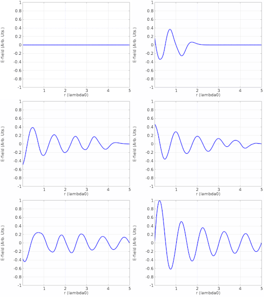
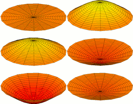
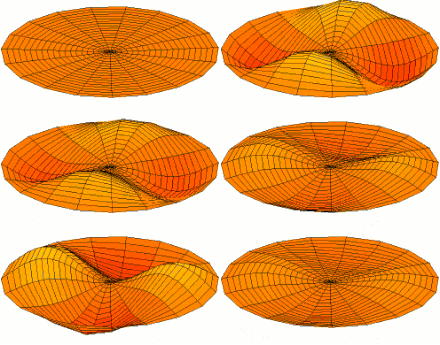
Standing waves can also occur in two- or three-dimensional resonators. With standing waves on two-dimensional membranes such as drumheads, illustrated in the animations above, the nodes become nodal lines, lines on the surface at which there is no movement, that separate regions vibrating with opposite phase. These nodal line patterns are called Chladni figures. In three-dimensional resonators, such as musical instrument sound boxes and microwave cavity resonators, there are nodal surfaces.
Standing wave ratio, phase, and energy transfer
If the two oppositely moving traveling waves are not of the same amplitude, they will not cancel completely at the nodes, the points where the waves are 180° out of phase, so the amplitude of the standing wave will not be zero at the nodes, but merely a minimum. Standing wave ratio (SWR) is the ratio of the amplitude at the antinode (maximum) to the amplitude at the node (minimum). A pure standing wave will have an infinite SWR. It will also have a constant phase at any point in space (but it may undergo a 180° inversion every half cycle). A finite, non-zero SWR indicates a wave that is partially stationary and partially travelling. Such waves can be decomposed into a superposition of two waves: a travelling wave component and a stationary wave component. An SWR of one indicates that the wave does not have a stationary component – it is purely a travelling wave, since the ratio of amplitudes is equal to 1.[9]
A pure standing wave does not transfer energy from the source to the destination.[10] However, the wave is still subject to losses in the medium. Such losses will manifest as a finite SWR, indicating a travelling wave component leaving the source to supply the losses. Even though the SWR is now finite, it may still be the case that no energy reaches the destination because the travelling component is purely supplying the losses. However, in a lossless medium, a finite SWR implies a definite transfer of energy to the destination.
Examples
One easy example to understand standing waves is two people shaking either end of a jump rope. If they shake in sync the rope can form a regular pattern of waves oscillating up and down, with stationary points along the rope where the rope is almost still (nodes) and points where the arc of the rope is maximum (antinodes).
Sound waves
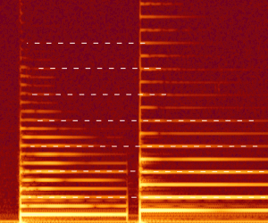
Standing waves are also observed in physical media such as strings and columns of air. Any waves traveling along the medium will reflect back when they reach the end. This effect is most noticeable in musical instruments where, at various multiples of a vibrating string or air column's natural frequency, a standing wave is created, allowing harmonics to be identified. Nodes occur at fixed ends and anti-nodes at open ends. If fixed at only one end, only odd-numbered harmonics are available. At the open end of a pipe the anti-node will not be exactly at the end as it is altered by its contact with the air and so end correction is used to place it exactly. The density of a string will affect the frequency at which harmonics will be produced; the greater the density the lower the frequency needs to be to produce a standing wave of the same harmonic.
Visible light
Standing waves are also observed in optical media such as optical waveguides and optical cavities. Lasers use optical cavities in the form of a pair of facing mirrors, which constitute a Fabry–Pérot interferometer. The gain medium in the cavity (such as a crystal) emits light coherently, exciting standing waves of light in the cavity.[13] The wavelength of light is very short (in the range of nanometers, 10−9 m) so the standing waves are microscopic in size. One use for standing light waves is to measure small distances, using optical flats.
X-rays
Interference between X-ray beams can form an X-ray standing wave (XSW) field.[14] Because of the short wavelength of X-rays (less than 1 nanometer), this phenomenon can be exploited for measuring atomic-scale events at material surfaces. The XSW is generated in the region where an X-ray beam interferes with a diffracted beam from a nearly perfect single crystal surface or a reflection from an X-ray mirror. By tuning the crystal geometry or X-ray wavelength, the XSW can be translated in space, causing a shift in the X-ray fluorescence or photoelectron yield from the atoms near the surface. This shift can be analyzed to pinpoint the location of a particular atomic species relative to the underlying crystal structure or mirror surface. The XSW method has been used to clarify the atomic-scale details of dopants in semiconductors,[15] atomic and molecular adsorption on surfaces,[16] and chemical transformations involved in catalysis.[17]
Mechanical waves
Standing waves can be mechanically induced into a solid medium using resonance. One easy to understand example is two people shaking either end of a jump rope. If they shake in sync, the rope will form a regular pattern with nodes and antinodes and appear to be stationary, hence the name standing wave. Similarly a cantilever beam can have a standing wave imposed on it by applying a base excitation. In this case the free end moves the greatest distance laterally compared to any location along the beam. Such a device can be used as a sensor to track changes in frequency or phase of the resonance of the fiber. One application is as a measurement device for dimensional metrology.[18][19]
Seismic waves
Standing surface waves on the Earth are observed as free oscillations of the Earth.
Faraday waves
The Faraday wave is a non-linear standing wave at the air-liquid interface induced by hydrodynamic instability. It can be used as a liquid-based template to assemble microscale materials.[20]
See also
Waves
Electronics
- Index of electronics articles:
- Cavity resonator
- Characteristic impedance
- Cymatics
- Impedance
- Normal mode
References and notes
- Alwyn Scott (ed), Encyclopedia of Nonlinear Science, p. 683, Routledge, 2006 ISBN 1135455589.
- Theodore Y. Wu, "Stability of nonlinear waves resonantly sustained", Nonlinear Instability of Nonparallel Flows: IUTAM Symposium Potsdam, New York, p. 368, Springer, 2012 ISBN 3642850847.
- Melde, Franz. Ueber einige krumme Flächen, welche von Ebenen, parallel einer bestimmten Ebene, durchschnitten, als Durchschnittsfigur einen Kegelschnitt liefern: Inaugural-Dissertation... Koch, 1859.
- Melde, Franz. "Ueber die Erregung stehender Wellen eines fadenförmigen Körpers." Annalen der Physik 185, no. 2 (1860): 193–215.
- Melde, Franz. Die Lehre von den Schwingungscurven...: mit einem Atlas von 11 Tafeln in Steindruck. JA Barth, 1864.
- Melde, Franz. "Akustische Experimentaluntersuchungen." Annalen der Physik 257, no. 3 (1884): 452–470.
-

- Blackstock, David T. (2000), "Fundamentals of Physical Acoustics" (PDF), Acoustical Society of America Journal, 109 (4): 1274–1276, Bibcode:2001ASAJ..109R1274B, doi:10.1121/1.1354982, ISBN 978-0-471-31979-5, 568 pages. See page 141.
- R S Rao, Microwave Engineering, pp. 153–154, PHI Learning, 2015 ISBN 8120351592.
- K A Tsokos, Physics for the IB Diploma, p. 251, Cambridge University Press, 2010 ISBN 0521138213.
- A Wave Dynamical Interpretation of Saturn's Polar Region Archived 2011-10-21 at the Wayback Machine, M. Allison, D. A. Godfrey, R. F. Beebe, Science vol. 247, pg. 1061 (1990)
- Barbosa Aguiar, Ana C. (2010). "A laboratory model of Saturn's North Polar Hexagon". Icarus. 206 (2): 755–763. Bibcode:2010Icar..206..755B. doi:10.1016/j.icarus.2009.10.022.
- Pedrotti, Frank L.; Pedrotti, Leno M. (2017). Introduction to Optics (3 ed.). Cambridge University Press. ISBN 978-1108428262.
- Batterman, Boris W.; Cole, Henderson (1964). "Dynamical Diffraction of X Rays by Perfect Crystals". Reviews of Modern Physics. 36 (3): 681–717. Bibcode:1964RvMP...36..681B. doi:10.1103/RevModPhys.36.681.
- Batterman, Boris W. (1969). "Detection of Foreign Atom Sites by Their X-Ray Fluorescence Scattering". Physical Review Letters. 22 (14): 703–705. Bibcode:1969PhRvL..22..703B. doi:10.1103/PhysRevLett.22.703.
- Golovchenko, J. A.; Patel, J. R.; Kaplan, D. R.; Cowan, P. L.; Bedzyk, M. J. (1982). "Solution to the Surface Registration Problem Using X-Ray Standing Waves" (PDF). Physical Review Letters. 49 (8): 560–563. Bibcode:1982PhRvL..49..560G. doi:10.1103/PhysRevLett.49.560.
- Feng, Z.; Kim, C.-Y.; Elam, J.W.; Ma, Q.; Zhang, Z.; Bedzyk, M.J. (2009). "Direct Atomic-Scale Observation of Redox-Induced Cation Dynamics in an Oxide-Supported Monolayer Catalyst: WOx/α-Fe2O3(0001)". J. Am. Chem. Soc. 131 (51): 18200–18201. doi:10.1021/ja906816y. PMID 20028144.
- Bauza, Marcin B.; Hocken, Robert J.; Smith, Stuart T.; Woody, Shane C. (2005). "Development of a virtual probe tip with an application to high aspect ratio microscale features". Review of Scientific Instruments. 76 (9): 095112–095112–8. Bibcode:2005RScI...76i5112B. doi:10.1063/1.2052027.
- "Precision Engineering and Manufacturing Solutions – IST Precision". www.insitutec.com. Archived from the original on 31 July 2016. Retrieved 28 April 2018.
- Chen, Pu (2014). "Microscale Assembly Directed by Liquid-Based Template". Advanced Materials. 26 (34): 5936–5941. doi:10.1002/adma.201402079. PMC 4159433. PMID 24956442.


