Geothermal heat pump
A geothermal heat pump (GHP) or ground source heat pump (GSHP) is a central heating and/or cooling system that transfers heat to or from the ground.
| Part of a series about |
| Sustainable energy |
|---|
 |
| Overview |
| Energy conservation |
| Renewable energy |
| Sustainable transport |
|
It uses the earth all the time, without any intermittency, as a heat source (in the winter) or a heat sink (in the summer). This design takes advantage of the moderate temperatures in the ground to boost efficiency and reduce the operational costs of heating and cooling systems, and may be combined with solar heating to form a geosolar system with even greater efficiency. They are also known by other names, including geoexchange, earth-coupled, earth energy systems. The engineering and scientific communities prefer the terms "geoexchange" or "ground source heat pumps" to avoid confusion with traditional geothermal power, which uses a high temperature heat source to generate electricity.[1] Ground source heat pumps harvest heat absorbed at the Earth's surface from solar energy. The temperature in the ground below 6 metres (20 ft) is roughly equal to the local mean annual air temperature (MAAT).[2][3][4]
Depending on latitude, the temperature beneath the upper 6 metres (20 ft) of Earth's surface maintains a nearly constant temperature reflecting the mean average annual air temperature[5] (in many areas, between 10 and 16 °C/50 and 60 °F),[6] if the temperature is undisturbed by the presence of a heat pump. Like a refrigerator or air conditioner, these systems use a heat pump to force the transfer of heat from the ground. Heat pumps can transfer heat from a cool space to a warm space, against the natural direction of flow, or they can enhance the natural flow of heat from a warm area to a cool one. The core of the heat pump is a loop of refrigerant pumped through a vapor-compression refrigeration cycle that moves heat. Air-source heat pumps are typically more efficient at heating than pure electric heaters, even when extracting heat from cold winter air, although efficiencies begin dropping significantly as outside air temperatures drop below 5 °C (41 °F). A ground source heat pump exchanges heat with the ground. This is much more energy-efficient because underground temperatures are more stable than air temperatures through the year. Seasonal variations drop off with depth and disappear below 7 metres (23 ft)[7] to 12 metres (39 ft)[8] due to thermal inertia. Like a cave, the shallow ground temperature is warmer than the air above during the winter and cooler than the air in the summer. A ground source heat pump extracts ground heat in the winter (for heating) and transfers heat back into the ground in the summer (for cooling). Some systems are designed to operate in one mode only, heating or cooling, depending on climate.
Geothermal pump systems reach fairly high coefficient of performance (CoP), 3 to 6, on the coldest of winter nights, compared to 1.75–2.5 for air-source heat pumps on cool days.[9] Ground source heat pumps (GSHPs) are among the most energy-efficient technologies for providing HVAC and water heating.[10][11]
Setup costs are higher than for conventional systems, but the difference is usually returned in energy savings in 3 to 10 years. Geothermal heat pump systems are reasonably warranted by manufacturers, and their working life is estimated at 25 years for inside components and 50+ years for the ground loop.[12] As of 2004, there are over one million units installed worldwide providing 12 GW of thermal capacity, with an annual growth rate of 10%.[13]
Differing terms and definitions
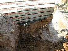
Some confusion exists with regard to the terminology of heat pumps and the use of the term "geothermal". "Geothermal" derives from the Greek and means "Earth heat" – which geologists and many laymen understand as describing hot rocks, volcanic activity or heat derived from deep within the earth. Though some confusion arises when the term "geothermal" is also used to apply to temperatures within the first 100 metres of the surface, this is "Earth heat" all the same, though it is largely influenced by stored energy from the sun.
History
The heat pump was described by Lord Kelvin in 1853 and developed by Peter Ritter von Rittinger in 1855. After experimenting with a freezer, Robert C. Webber built the first direct exchange ground-source heat pump in the late 1940s.[14] The first successful commercial project was installed in the Commonwealth Building (Portland, Oregon) in 1948, and has been designated a National Historic Mechanical Engineering Landmark by ASME.[15] The technology became popular in Sweden in the 1970s, and has been growing slowly in worldwide acceptance since then. Open loop systems dominated the market until the development of polybutylene pipe in 1979 made closed loop systems economically viable.[15] As of 2004, there are over a million units installed worldwide providing 12 GW of thermal capacity.[13] Each year, about 80,000 units are installed in the US (geothermal energy is used in all 50 U.S. states today, with great potential for near-term market growth and savings)[16] and 27,000 in Sweden.[13] In Finland, a geothermal heat pump was the most common heating system choice for new detached houses between 2006 and 2011 with market share exceeding 40%.[17]
Ground heat exchanger
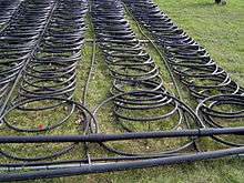
Heat pumps provide winter heating by extracting heat from a source and transferring it into a building. Heat can be extracted from any source, no matter how cold, but a warmer source allows higher efficiency. A ground source heat pump uses the top layer of the earth's crust as a source of heat, thus taking advantage of its seasonally moderated temperature.
In the summer, the process can be reversed so the heat pump extracts heat from the building and transfers it to the ground. Transferring heat to a cooler space takes less energy, so the cooling efficiency of the heat pump gains benefits from the lower ground temperature.
Ground source heat pumps employ a heat exchanger in contact with the ground or groundwater to extract or dissipate heat. This component accounts for anywhere from a fifth to half of the total system cost, and would be the most cumbersome part to repair or replace. Correctly sizing this component is necessary to assure long-term performance: the energy efficiency of the system improves with roughly 4% for every degree Celsius that is won through correct sizing, and the underground temperature balance must be maintained through proper design of the whole system. Incorrect design can result in the system freezing after a number of years or very inefficient system performance; thus accurate system design is critical to a successful system [18]
Shallow 3–8-foot (0.91–2.44 m) horizontal heat exchangers experience seasonal temperature cycles due to solar gains and transmission losses to ambient air at ground level. These temperature cycles lag behind the seasons because of thermal inertia, so the heat exchanger will harvest heat deposited by the sun several months earlier, while being weighed down in late winter and spring, due to accumulated winter cold. Deep vertical systems 100–500 feet (30–152 m) deep rely on migration of heat from surrounding geology, unless they are recharged annually by solar recharge of the ground or exhaust heat from air conditioning systems.
Several major design options are available for these, which are classified by fluid and layout. Direct exchange systems circulate refrigerant underground, closed loop systems use a mixture of anti-freeze and water, and open loop systems use natural groundwater.
Direct exchange (DX)
The direct exchange geothermal heat pump (DX) is the oldest type of geothermal heat pump technology. The ground-coupling is achieved through a single loop, circulating refrigerant, in direct thermal contact with the ground (as opposed to a combination of a refrigerant loop and a water loop). The refrigerant leaves the heat pump cabinet, circulates through a loop of copper tube buried underground, and exchanges heat with the ground before returning to the pump. The name "direct exchange" refers to heat transfer between the refrigerant loop and the ground without the use of an intermediate fluid. There is no direct interaction between the fluid and the earth; only heat transfer through the pipe wall. Direct exchange heat pumps are not to be confused with "water-source heat pumps" or "water loop heat pumps" since there is no water in the ground loop. ASHRAE defines the term ground-coupled heat pump to encompass closed loop and direct exchange systems, while excluding open loops.
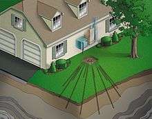
Direct exchange systems are more efficient and have potentially lower installation costs than closed loop water systems. Copper's high thermal conductivity contributes to the higher efficiency of the system, but heat flow is predominantly limited by the thermal conductivity of the ground, not the pipe. The main reasons for the higher efficiency are the elimination of the water pump (which uses electricity), the elimination of the water-to-refrigerant heat exchanger (which is a source of heat losses), and most importantly, the latent heat phase change of the refrigerant in the ground itself.
However, in case of leakage there is virtually no risk of contaminating the ground or the ground water. Contrary to water-source geothermal systems, direct exchange systems do not contain antifreeze. So, in case of a refrigerant leakage, the refrigerant currently used in most systems – R-410A – would immediately vaporize and seek the atmosphere. This is due to the low boiling point of R-410A: −51 °C (−60 °F). R-410A refrigerant replaces larger volumes of antifreeze mixtures used in water-source geothermal systems and presents no threat to aquifers or to the ground itself.
While they require more refrigerant and their tubing is more expensive per foot, a direct exchange earth loop is shorter than a closed water loop for a given capacity. A direct exchange system requires only 15 to 40% of the length of tubing and half the diameter of drilled holes, and the drilling or excavation costs are therefore lower. Refrigerant loops are less tolerant of leaks than water loops because gas can leak out through smaller imperfections. This dictates the use of brazed copper tubing, even though the pressures are similar to water loops. The copper loop must be protected from corrosion in acidic soil through the use of a sacrificial anode or other cathodic protection.
The U.S. Environmental Protection Agency conducted field monitoring of a direct geoexchange heat pump water heating system in a commercial application. The EPA reported that the system saved 75% of the electrical energy that would have been required by an electrical resistance water heating unit. According to the EPA, if the system is operated to capacity, it can avoid the emission of up to 7,100 pounds of CO2 and 15 pounds of NOx each year per ton of compressor capacity (or 42,600 lbs. of CO2 and 90 lbs. of NOx for a typical 6 tons of refrigeration (~21.5 kW) system).[19]
In Northern climates, although the earth temperature is cooler, so is the incoming water temperature, which enables the high efficiency systems to replace more energy that would otherwise be required of electric or fossil fuel fired systems. Any temperature above −40 °C (−40 °F) is sufficient to evaporate the refrigerant, and the direct exchange system can harvest energy through ice.
In extremely hot climates with dry soil, the addition of an auxiliary cooling module as a second condenser in line between the compressor and the earth loops increases efficiency and can further reduce the amount of earth loop to be installed.
Closed loop
Most installed systems have two loops on the ground side: the primary refrigerant loop is contained in the appliance cabinet where it exchanges heat with a secondary water loop that is buried underground. The secondary loop is typically made of high-density polyethylene pipe and contains a mixture of water and anti-freeze (propylene glycol, denatured alcohol or methanol). Monopropylene glycol has the least damaging potential when it might leak into the ground, and is therefore the only allowed anti-freeze in ground sources in an increasing number of European countries. After leaving the internal heat exchanger, the water flows through the secondary loop outside the building to exchange heat with the ground before returning. The secondary loop is placed below the frost line where the temperature is more stable, or preferably submerged in a body of water if available. Systems in wet ground or in water are generally more efficient than drier ground loops since water conducts and stores heat better than solids in sand or soil. If the ground is naturally dry, soaker hoses may be buried with the ground loop to keep it wet.
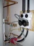
Closed loop systems need a heat exchanger between the refrigerant loop and the water loop, and pumps in both loops. Some manufacturers have a separate ground loop fluid pump pack, while some integrate the pumping and valving within the heat pump. Expansion tanks and pressure relief valves may be installed on the heated fluid side. Closed loop systems have lower efficiency than direct exchange systems, so they require longer and larger pipe to be placed in the ground, increasing excavation costs.
Closed loop tubing can be installed horizontally as a loop field in trenches or vertically as a series of long U-shapes in wells (see below). The size of the loop field depends on the soil type and moisture content, the average ground temperature and the heat loss and or gain characteristics of the building being conditioned. A rough approximation of the initial soil temperature is the average daily temperature for the region.
Vertical
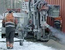
A vertical closed loop field is composed of pipes that run vertically in the ground. A hole is bored in the ground, typically 50 to 400 feet (15–122 m) deep, or a foundation pile of a building in which a circulating heat-carrying fluid absorbs (or discharges) heat from (or to) the ground.[20][21] Pipe pairs in the hole are joined with a U-shaped cross connector at the bottom of the hole or comprises two small-diameter high-density polyethylene (HDPE) tubes thermally fused to form a U-shaped bend at the bottom.[22] The space between the wall of the borehole and the U-shaped tubes is usually grouted completely with grouting material or, in some cases, partially filled with groundwater.[23] The borehole is commonly filled with a bentonite grout surrounding the pipe to provide a thermal connection to the surrounding soil or rock to improve the heat transfer. Thermally enhanced grouts are available to improve this heat transfer. Grout also protects the ground water from contamination, and prevents artesian wells from flooding the property. Vertical loop fields are typically used when there is a limited area of land available. Bore holes are spaced at least 5–6 m apart and the depth depends on ground and building characteristics. For illustration, a detached house needing 10 kW (3 ton) of heating capacity might need three boreholes 80 to 110 m (260 to 360 ft) deep.[24] During the cooling season, the local temperature rise in the bore field is influenced most by the moisture travel in the soil. Reliable heat transfer models have been developed through sample bore holes as well as other tests. In a foundation pile GHE (or energy pile), the heat transfer tubes are inside the steel frame of a foundation pile. There are various possible shapes. Foundation piles are usually much shallower than boreholes and have a greater radius. Since energy piles generally require less land area, this technology is evoking increasing interest in the ground-source heat pumps community.
Horizontal
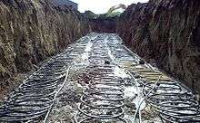
A horizontal closed loop field is composed of pipes that run horizontally in the ground. A long horizontal trench, deeper than the frost line, is dug and U-shaped or slinky coils are placed horizontally inside the same trench. Excavation for shallow horizontal loop fields is about half the cost of vertical drilling, so this is the most common layout used wherever there is adequate land available. For illustration, a detached house needing 10 kW (3 ton) of heating capacity might need three loops 120 to 180 m (390 to 590 ft) long of NPS 3/4 (DN 20) or NPS 1.25 (DN 32) polyethylene tubing at a depth of 1 to 2 m (3.3 to 6.6 ft).[25]
The depth at which the loops are placed significantly influences the energy consumption of the heat pump in two opposite ways: shallow loops tend to indirectly absorb more heat from the sun, which is helpful, especially when the ground is still cold after a long winter. On the other hand, shallow loops are also cooled down much more readily by weather changes, especially during long cold winters, when heating demand peaks. Often, the second effect is much greater than the first one, leading to higher costs of operation for the more shallow ground loops. This problem can be reduced by increasing both the depth and the length of piping, thereby significantly increasing costs of installation. However, such expenses might be deemed feasible as they may result in lower operating costs. Recent studies show that utilization of a non-homogeneous soil profile with a layer of low conductive material above the ground pipes can help mitigate the adverse effects of shallow pipe burial depth. The intermediate blanket with lower conductivity than the surrounding soil profile demonstrated the potential to increase the energy extraction rates from the ground to as high as 17% for a cold climate and about 5–6% for a relatively moderate climate.[26]
A slinky (also called coiled) closed loop field is a type of horizontal closed loop where the pipes overlay each other (not a recommended method). The easiest way of picturing a slinky field is to imagine holding a slinky on the top and bottom with your hands and then moving your hands in opposite directions. A slinky loop field is used if there is not adequate room for a true horizontal system, but it still allows for an easy installation. Rather than using straight pipe, slinky coils use overlapped loops of piping laid out horizontally along the bottom of a wide trench. Depending on soil, climate and the heat pump's run fraction, slinky coil trenches can be up to two thirds shorter than traditional horizontal loop trenches. Slinky coil ground loops are essentially a more economical and space efficient version of a horizontal ground loop.[27]
Radial or directional drilling
As an alternative to trenching, loops may be laid by mini horizontal directional drilling (mini-HDD). This technique can lay piping under yards, driveways, gardens or other structures without disturbing them, with a cost between those of trenching and vertical drilling. This system also differs from horizontal & vertical drilling as the loops are installed from one central chamber, further reducing the ground space needed. Radial drilling is often installed retroactively (after the property has been built) due to the small nature of the equipment used and the ability to bore beneath existing constructions.
Pond

A closed pond loop is not common because it depends on proximity to a body of water, where an open loop system is usually preferable. A pond loop may be advantageous where poor water quality precludes an open loop, or where the system heat load is small. A pond loop consists of coils of pipe similar to a slinky loop attached to a frame and located at the bottom of an appropriately sized pond or water source. Artificial ponds (costing €30/m³) are used as heat storage (up to 90% efficient) in some central solar heating plants, which later extract the heat (similar to ground storage) via a large heat pump to supply district heating.[28][29]
Analysis of heat transfer by GHEs
A huge challenge in predicting the thermal response of a GHE is the diversity of the time and space scales involved. Four space scales and eight time scales are involved in the heat transfer of GHEs. The first space scale having practical importance is the diameter of the borehole (~ 0.1 m) and the associated time is on the order of 1 hr, during which the effect of the heat capacity of the backfilling material is significant. The second important space dimension is the half distance between two adjacent boreholes, which is on the order of several meters. The corresponding time is on the order of a month, during which the thermal interaction between adjacent boreholes is important. The largest space scale can be tens of meters or more, such as the half length of a borehole and the horizontal scale of a GHE cluster. The time scale involved is as long as the lifetime of a GHE (decades).[30]
The short-term hourly temperature response of the ground is vital for analyzing the energy of ground-source heat pump systems and for their optimum control and operation. By contrast, the long-term response determines the overall feasibility of a system from the standpoint of life cycle. Addressing the complete spectrum of time scales require vast computational resources.
The main questions that engineers may ask in the early stages of designing a GHE are (a) what the heat transfer rate of a GHE as a function of time is, given a particular temperature difference between the circulating fluid and the ground, and (b) what the temperature difference as a function of time is, given a required heat exchange rate. In the language of heat transfer, the two questions can probably be expressed as
where Tf is the average temperature of the circulating fluid, T0 is the effective, undisturbed temperature of the ground, ql is the heat transfer rate of the GHE per unit time per unit length (W/m), and R is the total thermal resistance (m.K/W).R(t) is often an unknown variable that needs to be determined by heat transfer analysis. Despite R(t) being a function of time, analytical models exclusively decompose it into a time-independent part and a time-dependent part to simplify the analysis.
Various models for the time-independent and time-dependent R can be found in the references.[20][21] Further, a Thermal response test is often performed to make a deterministic analysis of ground thermal conductivity to optimize the loopfield size, especially for larger commercial sites (e.g., over 10 wells).
Open loop
In an open loop system (also called a groundwater heat pump), the secondary loop pumps natural water from a well or body of water into a heat exchanger inside the heat pump. ASHRAE calls open loop systems groundwater heat pumps or surface water heat pumps, depending on the source. Heat is either extracted or added by the primary refrigerant loop, and the water is returned to a separate injection well, irrigation trench, tile field or body of water. The supply and return lines must be placed far enough apart to ensure thermal recharge of the source. Since the water chemistry is not controlled, the appliance may need to be protected from corrosion by using different metals in the heat exchanger and pump. Limescale may foul the system over time and require periodic acid cleaning. This is much more of a problem with cooling systems than heating systems.[31] Also, as fouling decreases the flow of natural water, it becomes difficult for the heat pump to exchange building heat with the groundwater. If the water contains high levels of salt, minerals, iron bacteria or hydrogen sulfide, a closed loop system is usually preferable.
Deep lake water cooling uses a similar process with an open loop for air conditioning and cooling. Open loop systems using ground water are usually more efficient than closed systems because they are better coupled with ground temperatures. Closed loop systems, in comparison, have to transfer heat across extra layers of pipe wall and dirt.
A growing number of jurisdictions have outlawed open-loop systems that drain to the surface because these may drain aquifers or contaminate wells. This forces the use of more environmentally sound injection wells or a closed loop system.
Standing column well
A standing column well system is a specialized type of open loop system. Water is drawn from the bottom of a deep rock well, passed through a heat pump, and returned to the top of the well, where traveling downwards it exchanges heat with the surrounding bedrock.[32] The choice of a standing column well system is often dictated where there is near-surface bedrock and limited surface area is available. A standing column is typically not suitable in locations where the geology is mostly clay, silt, or sand. If bedrock is deeper than 200 feet (61 m) from the surface, the cost of casing to seal off the overburden may become prohibitive.
A multiple standing column well system can support a large structure in an urban or rural application. The standing column well method is also popular in residential and small commercial applications. There are many successful applications of varying sizes and well quantities in the many boroughs of New York City, and is also the most common application in the New England states. This type of ground source system has some heat storage benefits, where heat is rejected from the building and the temperature of the well is raised, within reason, during the summer cooling months which can then be harvested for heating in the winter months, thereby increasing the efficiency of the heat pump system. As with closed loop systems, sizing of the standing column system is critical in reference to the heat loss and gain of the existing building. As the heat exchange is actually with the bedrock, using water as the transfer medium, a large amount of production capacity (water flow from the well) is not required for a standing column system to work. However, if there is adequate water production, then the thermal capacity of the well system can be enhanced by discharging a small percentage of system flow during the peak Summer and Winter months.
Since this is essentially a water pumping system, standing column well design requires critical considerations to obtain peak operating efficiency. Should a standing column well design be misapplied, leaving out critical shut-off valves for example, the result could be an extreme loss in efficiency and thereby cause operational cost to be higher than anticipated.
Building distribution
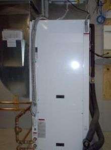
The heat pump is the central unit that becomes the heating and cooling plant for the building. Some models may cover space heating, space cooling, (space heating via conditioned air, hydronic systems and / or radiant heating systems), domestic or pool water preheat (via the desuperheater function), demand hot water, and driveway ice melting all within one appliance with a variety of options with respect to controls, staging and zone control. The heat may be carried to its end use by circulating water or forced air. Almost all types of heat pumps are produced for commercial and residential applications.
Liquid-to-air heat pumps (also called water-to-air) output forced air, and are most commonly used to replace legacy forced air furnaces and central air conditioning systems. There are variations that allow for split systems, high-velocity systems, and ductless systems. Heat pumps cannot achieve as high a fluid temperature as a conventional furnace, so they require a higher volume flow rate of air to compensate. When retrofitting a residence, the existing duct work may have to be enlarged to reduce the noise from the higher air flow.
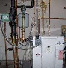
Liquid-to-water heat pumps (also called water-to-water) are hydronic systems that use water to carry heating or cooling through the building. Systems such as radiant underfloor heating, baseboard radiators, conventional cast iron radiators would use a liquid-to-water heat pump. These heat pumps are preferred for pool heating or domestic hot water pre-heat. Heat pumps can only heat water to about 50 °C (122 °F) efficiently, whereas a boiler normally reaches 65–95 °C (149–203 °F). Legacy radiators designed for these higher temperatures may have to be doubled in numbers when retrofitting a home. A hot water tank will still be needed to raise water temperatures above the heat pump's maximum, but pre-heating will save 25–50% of hot water costs.
Ground source heat pumps are especially well matched to underfloor heating and baseboard radiator systems which only require warm temperatures of 40 °C (104 °F) to work well. Thus they are ideal for open plan offices. Using large surfaces such as floors, as opposed to radiators, distributes the heat more uniformly and allows for a lower water temperature. Wood or carpet floor coverings dampen this effect because the thermal transfer efficiency of these materials is lower than that of masonry floors (tile, concrete). Underfloor piping, ceiling or wall radiators can also be used for cooling in dry climates, although the temperature of the circulating water must be above the dew point to ensure that atmospheric humidity does not condense on the radiator.
Combination heat pumps are available that can produce forced air and circulating water simultaneously and individually. These systems are largely being used for houses that have a combination of air and liquid conditioning needs, for example central air conditioning and pool heating.
Seasonal thermal storage
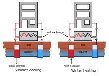
The efficiency of ground source heat pumps can be greatly improved by using seasonal thermal energy storage and interseasonal heat transfer.[33] Heat captured and stored in thermal banks in the summer can be retrieved efficiently in the winter. Heat storage efficiency increases with scale, so this advantage is most significant in commercial or district heating systems.
Geosolar combisystems have been used to heat and cool a greenhouse using an aquifer for thermal storage.[29][34] In summer, the greenhouse is cooled with cold ground water. This heats the water in the aquifer which can become a warm source for heating in winter.[34][35] The combination of cold and heat storage with heat pumps can be combined with water/humidity regulation. These principles are used to provide renewable heat and renewable cooling[36] to all kinds of buildings.
Also the efficiency of existing small heat pump installations can be improved by adding large, cheap, water filled solar collectors. These may be integrated into a to-be-overhauled parking lot, or in walls or roof constructions by installing one-inch PE pipes into the outer layer.
Thermal efficiency
The net thermal efficiency of a heat pump should take into account the efficiency of electricity generation and transmission, typically about 30%.[13] Since a heat pump moves three to five times more heat energy than the electric energy it consumes, the total energy output is much greater than the electrical input. This results in net thermal efficiencies greater than 300% as compared to radiant electric heat being 100% efficient. Traditional combustion furnaces and electric heaters can never exceed 100% efficiency.
Geothermal heat pumps can reduce energy consumption— and corresponding air pollution emissions—up to 44% compared to air source heat pumps and up to 72% compared to electric resistance heating with standard air-conditioning equipment.[37]
The dependence of net thermal efficiency on the electricity infrastructure tends to be an unnecessary complication for consumers and is not applicable to hydroelectric power, so performance of heat pumps is usually expressed as the ratio of heating output or heat removal to electricity input. Cooling performance is typically expressed in units of BTU/hr/watt as the energy efficiency ratio (EER), while heating performance is typically reduced to dimensionless units as the coefficient of performance (COP). The conversion factor is 3.41 BTU/hr/watt. Performance is influenced by all components of the installed system, including the soil conditions, the ground-coupled heat exchanger, the heat pump appliance, and the building distribution, but is largely determined by the "lift" between the input temperature and the output temperature.
For the sake of comparing heat pump appliances to each other, independently from other system components, a few standard test conditions have been established by the American Refrigerant Institute (ARI) and more recently by the International Organization for Standardization. Standard ARI 330 ratings were intended for closed loop ground-source heat pumps, and assume secondary loop water temperatures of 25 °C (77 °F) for air conditioning and 0 °C (32 °F) for heating. These temperatures are typical of installations in the northern US. Standard ARI 325 ratings were intended for open loop ground-source heat pumps, and include two sets of ratings for groundwater temperatures of 10 °C (50 °F) and 21 °C (70 °F). ARI 325 budgets more electricity for water pumping than ARI 330. Neither of these standards attempt to account for seasonal variations. Standard ARI 870 ratings are intended for direct exchange ground-source heat pumps. ASHRAE transitioned to ISO 13256-1 in 2001, which replaces ARI 320, 325 and 330. The new ISO standard produces slightly higher ratings because it no longer budgets any electricity for water pumps.[1]
Efficient compressors, variable speed compressors and larger heat exchangers all contribute to heat pump efficiency. Residential ground source heat pumps on the market today have standard COPs ranging from 2.4 to 5.0 and EERs ranging from 10.6 to 30.[1][38] To qualify for an Energy Star label, heat pumps must meet certain minimum COP and EER ratings which depend on the ground heat exchanger type. For closed loop systems, the ISO 13256-1 heating COP must be 3.3 or greater and the cooling EER must be 14.1 or greater.[39]
Actual installation conditions may produce better or worse efficiency than the standard test conditions. COP improves with a lower temperature difference between the input and output of the heat pump, so the stability of ground temperatures is important. If the loop field or water pump is undersized, the addition or removal of heat may push the ground temperature beyond standard test conditions, and performance will be degraded. Similarly, an undersized blower may allow the plenum coil to overheat and degrade performance.
Soil without artificial heat addition or subtraction and at depths of several metres or more remains at a relatively constant temperature year round. This temperature equates roughly to the average annual air-temperature of the chosen location, usually 7–12 °C (45–54 °F) at a depth of 6 metres (20 ft) in the northern US. Because this temperature remains more constant than the air temperature throughout the seasons, geothermal heat pumps perform with far greater efficiency during extreme air temperatures than air conditioners and air-source heat pumps.
Standards ARI 210 and 240 define Seasonal Energy Efficiency Ratio (SEER) and Heating Seasonal Performance Factors (HSPF) to account for the impact of seasonal variations on air source heat pumps. These numbers are normally not applicable and should not be compared to ground source heat pump ratings. However, Natural Resources Canada has adapted this approach to calculate typical seasonally adjusted HSPFs for ground-source heat pumps in Canada.[24] The NRC HSPFs ranged from 8.7 to 12.8 BTU/hr/watt (2.6 to 3.8 in nondimensional factors, or 255% to 375% seasonal average electricity utilization efficiency) for the most populated regions of Canada. When combined with the thermal efficiency of electricity, this corresponds to net average thermal efficiencies of 100% to 150%.
Environmental impact
The US Environmental Protection Agency (EPA) has called ground source heat pumps the most energy-efficient, environmentally clean, and cost-effective space conditioning systems available.[40] Heat pumps offer significant emission reductions potential, particularly where they are used for both heating and cooling and where the electricity is produced from renewable resources.
GSHPs have unsurpassed thermal efficiencies and produce zero emissions locally, but their electricity supply includes components with high greenhouse gas emissions, unless the owner has opted for a 100% renewable energy supply. Their environmental impact therefore depends on the characteristics of the electricity supply and the available alternatives.
| Country | Electricity CO2 Emissions Intensity | GHG savings relative to | ||
|---|---|---|---|---|
| natural gas | heating oil | electric heating | ||
| Canada | 223 ton/GWh[41][42][43] | 2.7 ton/yr | 5.3 ton/yr | 3.4 ton/yr |
| Russia | 351 ton/GWh[41][42] | 1.8 ton/yr | 4.4 ton/yr | 5.4 ton/yr |
| US | 676 ton/GWh[42] | −0.5 ton/yr | 2.2 ton/yr | 10.3 ton/yr |
| China | 839 ton/GWh[41][42] | −1.6 ton/yr | 1.0 ton/yr | 12.8 ton/yr |
The GHG emissions savings from a heat pump over a conventional furnace can be calculated based on the following formula:[7]
- HL = seasonal heat load ≈ 80 GJ/yr for a modern detached house in the northern US
- FI = emissions intensity of fuel = 50 kg(CO2)/GJ for natural gas, 73 for heating oil, 0 for 100% renewable energy such as wind, hydro, photovoltaic or solar thermal
- AFUE = furnace efficiency ≈ 95% for a modern condensing furnace
- COP = heat pump coefficient of performance ≈ 3.2 seasonally adjusted for northern US heat pump
- EI = emissions intensity of electricity ≈ 200–800 ton(CO2)/GWh, depending on region
Ground-source heat pumps always produce fewer greenhouse gases than air conditioners, oil furnaces, and electric heating, but natural gas furnaces may be competitive depending on the greenhouse gas intensity of the local electricity supply. In countries like Canada and Russia with low emitting electricity infrastructure, a residential heat pump may save 5 tons of carbon dioxide per year relative to an oil furnace, or about as much as taking an average passenger car off the road. But in cities like Beijing or Pittsburgh that are highly reliant on coal for electricity production, a heat pump may result in 1 or 2 tons more carbon dioxide emissions than a natural gas furnace. For areas not served by utility natural gas infrastructure, however, no better alternative exists.
The fluids used in closed loops may be designed to be biodegradable and non-toxic, but the refrigerant used in the heat pump cabinet and in direct exchange loops was, until recently, chlorodifluoromethane, which is an ozone depleting substance.[1] Although harmless while contained, leaks and improper end-of-life disposal contribute to enlarging the ozone hole. For new construction, this refrigerant is being phased out in favor of the ozone-friendly but potent greenhouse gas R410A. The EcoCute water heater is an air-source heat pump that uses carbon dioxide as its working fluid instead of chlorofluorocarbons. Open loop systems (i.e. those that draw ground water as opposed to closed loop systems using a borehole heat exchanger) need to be balanced by reinjecting the spent water. This prevents aquifer depletion and the contamination of soil or surface water with brine or other compounds from underground.
Before drilling, the underground geology needs to be understood, and drillers need to be prepared to seal the borehole, including preventing penetration of water between strata. The unfortunate example is a geothermal heating project in Staufen im Breisgau, Germany which seems the cause of considerable damage to historical buildings there. In 2008, the city centre was reported to have risen 12 cm,[44] after initially sinking a few millimeters.[45] The boring tapped a naturally pressurized aquifer, and via the borehole this water entered a layer of anhydrite, which expands when wet as it forms gypsum. The swelling will stop when the anhydrite is fully reacted, and reconstruction of the city center "is not expedient until the uplift ceases." By 2010 sealing of the borehole had not been accomplished.[46][47][48] By 2010, some sections of town had risen by 30 cm.[49]
Ground-source heat pump technology, like building orientation, is a natural building technique (bioclimatic building).
Economics
Ground source heat pumps are characterized by high capital costs and low operational costs compared to other HVAC systems. Their overall economic benefit depends primarily on the relative costs of electricity and fuels, which are highly variable over time and across the world. Based on recent prices, ground-source heat pumps currently have lower operational costs than any other conventional heating source almost everywhere in the world. Natural gas is the only fuel with competitive operational costs, and only in a handful of countries where it is exceptionally cheap, or where electricity is exceptionally expensive.[7] In general, a homeowner may save anywhere from 20% to 60% annually on utilities by switching from an ordinary system to a ground-source system.[50][51]
Capital costs and system lifespan have received much less study until recently, and the return on investment is highly variable. The most recent data from an analysis of 2011–2012 incentive payments in the state of Maryland showed an average cost of residential systems of $1.90 per watt, or about $26,700 for a typical (4 ton/14 kW) home system.[52] An older study found the total installed cost for a system with 10 kW (3 ton) thermal capacity for a detached rural residence in the US averaged $8000–$9000 in 1995 US dollars.[53] More recent studies found an average cost of $14,000 in 2008 US dollars for the same size system.[54][55] The US Department of Energy estimates a price of $7500 on its website, last updated in 2008.[56] One source in Canada placed prices in the range of $30,000–$34,000 Canadian dollars.[57] The rapid escalation in system price has been accompanied by rapid improvements in efficiency and reliability. Capital costs are known to benefit from economies of scale, particularly for open loop systems, so they are more cost-effective for larger commercial buildings and harsher climates. The initial cost can be two to five times that of a conventional heating system in most residential applications, new construction or existing. In retrofits, the cost of installation is affected by the size of living area, the home's age, insulation characteristics, the geology of the area, and location of the property. Proper duct system design and mechanical air exchange should be considered in the initial system cost.
| Country | Payback period for replacing | ||
|---|---|---|---|
| natural gas | heating oil | electric heating | |
| Canada | 13 years | 3 years | 6 years |
| US | 12 years | 5 years | 4 years |
| Germany | net loss | 8 years | 2 years |
|
Notes:
| |||
Capital costs may be offset by government subsidies; for example, Ontario offered $7000 for residential systems installed in the 2009 fiscal year. Some electric companies offer special rates to customers who install a ground-source heat pump for heating or cooling their building.[58] Where electrical plants have larger loads during summer months and idle capacity in the winter, this increases electrical sales during the winter months. Heat pumps also lower the load peak during the summer due to the increased efficiency of heat pumps, thereby avoiding costly construction of new power plants. For the same reasons, other utility companies have started to pay for the installation of ground-source heat pumps at customer residences. They lease the systems to their customers for a monthly fee, at a net overall saving to the customer.
The lifespan of the system is longer than conventional heating and cooling systems. Good data on system lifespan is not yet available because the technology is too recent, but many early systems are still operational today after 25–30 years with routine maintenance. Most loop fields have warranties for 25 to 50 years and are expected to last at least 50 to 200 years.[50][59] Ground-source heat pumps use electricity for heating the house. The higher investment above conventional oil, propane or electric systems may be returned in energy savings in 2–10 years for residential systems in the US.[12][51][59] If compared to natural gas systems, the payback period can be much longer or non-existent. The payback period for larger commercial systems in the US is 1–5 years, even when compared to natural gas.[51] Additionally, because geothermal heat pumps usually have no outdoor compressors or cooling towers, the risk of vandalism is reduced or eliminated, potentially extending a system's lifespan.[60]
Ground source heat pumps are recognized as one of the most efficient heating and cooling systems on the market. They are often the second-most cost effective solution in extreme climates (after co-generation), despite reductions in thermal efficiency due to ground temperature. (The ground source is warmer in climates that need strong air conditioning, and cooler in climates that need strong heating.) The financial viability of these systems depends on the adequate sizing of ground heat exchangers (GHEs), which generally contribute the most to the overall capital costs of GSHP systems.[61]
Commercial systems maintenance costs in the US have historically been between $0.11 to $0.22 per m2 per year in 1996 dollars, much less than the average $0.54 per m2 per year for conventional HVAC systems.[15]
Governments that promote renewable energy will likely offer incentives for the consumer (residential), or industrial markets. For example, in the United States, incentives are offered both on the state and federal levels of government.[62] In the United Kingdom the Renewable Heat Incentive provides a financial incentive for generation of renewable heat based on metered readings on an annual basis for 20 years for commercial buildings. The domestic Renewable Heat Incentive is due to be introduced in Spring 2014[63] for seven years and be based on deemed heat.
Installation
Because of the technical knowledge and equipment needed to design and size the system properly (and install the piping if heat fusion is required), a GSHP system installation requires a professional's services. Several installers have published real-time views of system performance in an online community of recent residential installations. The International Ground Source Heat Pump Association (IGSHPA),[64] Geothermal Exchange Organization (GEO),[65] the Canadian GeoExchange Coalition and the Ground Source Heat Pump Association maintain listings of qualified installers in the US, Canada and the UK.[66] Furthermore, detailed analysis of Soil thermal conductivity for horizontal systems and formation thermal conductivity for vertical systems will generally result in more accurately design systems with a higher efficiency.[67]
See also
- Absorption heat pump
- Ground-coupled heat exchanger
- Cold district heating
- Solar thermal cooling
- Thermosiphon
- Renewable heat
- International Ground Source Heat Pump Association
- Glossary of geothermal heating and cooling
- Uniform Mechanical Code
- Spiral ground heat exchangers for heat pump applications
References
- Rafferty, Kevin (April 1997). "An Information Survival Kit for the Prospective Residential Geothermal Heat Pump Owner" (PDF). Geo-Heat Centre Quarterly Bulletin. 18 (2). Klmath Falls, Oregon: Oregon Institute of Technology. pp. 1–11. ISSN 0276-1084. Archived from the original (PDF) on 17 February 2012. Retrieved 2009-03-21. The author issued an updated version of this article in February 2001.
- "Mean Annual Air Temperature – MATT – Ground temperature – Renewable Energy – Interseasonal Heat Transfer – Solar Thermal Collectors – Ground Source Heat Pumps – Renewable Cooling". www.icax.co.uk. Retrieved 19 March 2018.
- "Mean Annual Air Temperature - MATT". www.icax.co.uk.
- "Ground Temperatures as a Function of Location, Season, and Depth". builditsolar.com.
- "Groundwater temperature's measurement and significance - National Groundwater Association". National Groundwater Association. 23 August 2015.
- "Geothermal Technologies Program: Geothermal Basics". US Department of Energy. Archived from the original on 2008-10-04. Retrieved 2011-03-30.
- Hanova, J; Dowlatabadi, H (9 November 2007). "Strategic GHG reduction through the use of ground source heat pump technology" (PDF). Environmental Research Letters. 2. UK: IOP Publishing. pp. 044001 8pp. Bibcode:2007ERL.....2d4001H. doi:10.1088/1748-9326/2/4/044001. ISSN 1748-9326. Retrieved 2009-03-22.
- Tomislav Kurevija, Domagoj Vulin, Vedrana Krapec. "Influence of Undisturbed Ground Temperature and Geothermal Gradient on the Sizing of Borehole Heat Exchangers" page 1262 Faculty of Mining, Geology and Petroleum Engineering, University of Zagreb,May 2011. Accessed: October 2013.
- "Energy Savers: Geothermal Heat Pumps". Energysavers.gov. Archived from the original on 2011-01-01. Retrieved 2011-03-30.
- "Geothermal Technologies Program: Tennessee Energy Efficient Schools Initiative Ground Source Heat Pumps". Apps1.eere.energy.gov. 2010-03-29. Archived from the original on 2010-05-28. Retrieved 2011-03-30.
- "COLORADO RENEWABLE ENERGY SOCIETY – Geothermal Energy". Cres-energy.org. 2001-10-25. Archived from the original on 2011-07-16. Retrieved 2011-03-30.
- "Energy Savers: Geothermal Heat Pumps". Apps1.eere.energy.gov. 2009-02-24. Retrieved 2009-06-08.
- Lund, J.; Sanner, B.; Rybach, L.; Curtis, R.; Hellström, G. (September 2004). "Geothermal (Ground Source) Heat Pumps, A World Overview" (PDF). Geo-Heat Centre Quarterly Bulletin. 25 (3). Klmath Falls, Oregon: Oregon Institute of Technology. pp. 1–10. ISSN 0276-1084. Retrieved 2009-03-21.
- "History". About Us. International Ground Source Heat Pump Association. Archived from the original on 2009-04-04. Retrieved 2009-03-24.
- Bloomquist, R. Gordon (December 1999). "Geothermal Heat Pumps, Four Plus Decades of Experience" (PDF). Geo-Heat Centre Quarterly Bulletin. 20 (4). Klmath Falls, Oregon: Oregon Institute of Technology. pp. 13–18. ISSN 0276-1084. Retrieved 2009-03-21.
- "Geothermal – The Energy Under Our Feet: Geothermal Resources Estimates for the United States" (PDF). Retrieved 2011-03-30.
- "Choosing a heating system".
- "GSHC Viability and Design – Carbon Zero Consulting". carbonzeroco.com. Retrieved 19 March 2018.
- "Environmental Technology Verification Report" (PDF). U.S. Environmental Protection Agency. Archived from the original (PDF) on 2008-02-27. Retrieved December 3, 2015.
- Li M, Lai ACK. Review of analytical models for heat transfer by vertical ground heat exchangers (GHEs): A perspective of time and space scales, Applied Energy 2015; 151: 178-191.
- Hellstrom G. Ground heat storage – thermal analysis of duct storage systems I. Theory. Lund: University of Lund; 1991.
- ASHRAE. ASHRAE handbook: HVAC applications. Atlanta: ASHRAE, Inc; 2011.
- Kavanaugh SK, Rafferty K. Ground-source heat pumps: Design of geothermal systems for commercial and institutional buildings. Atlanta, GA: American Society of Heating, Refrigerating and Air-Conditioning Engineers, Inc.; 1997.
- "Ground Source Heat Pumps (Earth Energy Systems)". Heating and Cooling with a Heat Pump. Natural Resources Canada, Office of Energy Efficiency. Archived from the original on 2009-04-03. Retrieved 2009-03-24. Note: contrary to air-source conventions, the NRC's HSPF numbers are in units of BTU/hr/watt. Divide these numbers by 3.41 BTU/hr/watt to arrive at non-dimensional units comparable to ground-source COPs and air-source HSPF.
- Chiasson, A.D. (1999). "Advances in modeling of ground source heat pump systems" (PDF). Oklahoma State University. Retrieved 2009-04-23. Cite journal requires
|journal=(help) - Rezaei, B.; Amir, Kolahdouz; Dargush, G. F.; Weber, A. S. (2012a). "Ground source heat pump pipe performance with Tire Derived Aggregate". International Journal of Heat and Mass Transfer. 55 (11–12): 2844–2853. doi:10.1016/j.ijheatmasstransfer.2012.02.004.
- "Geothermal Ground Loops". Informed Building. Retrieved 2009-06-08.
- Epp, Baerbel (17 May 2019). "Seasonal pit heat storage: Cost benchmark of 30 EUR/m³". Solarthermalworld. Archived from the original on 2 February 2020.
- Kallesøe, A.J. & Vangkilde-Pedersen, T. "Underground Thermal Energy Storage (UTES) - 4 PTES (Pit Thermal Energy Storage), 10 MB" (PDF). www.heatstore.eu. p. 99.CS1 maint: multiple names: authors list (link)
- Li M, Li P, Chan V, Lai ACK. Full-scale temperature response function (G-function) for heat transfer by borehole ground heat exchangers (GHEs) from sub-hour to decades. Appl Energy 2014; 136: 197-205.
- Hard water#Indices
- Orio, Carl D.; Johnson, Carl N.; Rees, Simon J.; Chiasson, A.; Deng, Zheng; Spitler, Jeffrey D. (2004). "A Survey of Standing Column Well Installations in North America" (PDF). ASHRAE Transactions. 11 (4). ASHRAE. pp. 637–655. Archived from the original (PDF) on 2010-06-26. Retrieved 2009-03-25.
- "Interseasonal Heat Transfer". Icax.co.uk. Retrieved 2011-09-16.
- Van Passel, Willy; Sourbron, Maarten; Verplaetsen, Filip; Leroy, Luc; Somers, Yvan; Verheyden, Johan; Coupé, Koen. Organisatie voor Duurzame Energie Vlaanderen (ed.). Warmtepompen voor woningverwarming (PDF). p. 28. Archived from the original (PDF) on 2009-03-18. Retrieved 2009-03-23.
- "Schematic of similar system of aquifers with fans-regulation". Zonneterp.nl. 2005-11-11. Retrieved 2011-03-30.
- "Capture, storage and release of Renewable Cooling". Icax.co.uk. Retrieved 2011-03-30.
- Geothermal Heat Pumps. National Renewable Energy Laboratory.
- "AHRI Directory of water-to-air geothermal heat pumps".
- "Energy Star Program Requirements for Geothermal Heat PUmps" (PDF). Partner Commitments. Energy Star. Retrieved 2009-03-24.
- Environmental Protection Agency (1993). "Space Conditioning: The Next Frontier – Report 430-R-93-004". EPA. Cite journal requires
|journal=(help) - European Environment Agency (2008). Energy and environment report 2008. EEA Report. No 6/2008. Luxemburg: Office for Official Publications of the European Communities. p. 83. doi:10.2800/10548. ISBN 978-92-9167-980-5. ISSN 1725-9177. Retrieved 2009-03-22.
- Energy Information Administration, US Department of Energy (2007). "Voluntary Reporting of Greenhouse Gases, Electricity Emission Factors" (PDF). Retrieved 2009-03-22.
- "annex 9". National Inventory Report 1990–2006:Greenhouse Gas Sources and Sinks in Canada. Canada's Greenhouse Gas Inventory. Government of Canada. May 2008. ISBN 978-1-100-11176-6. ISSN 1706-3353.
- Spiegel.de report on recent geological changes (in German, partial translation)
- Pancevski, Bojan (30 March 2008). "Geothermal probe sinks German city". Retrieved 19 March 2018 – via www.telegraph.co.uk.
- FORMACIJE, A (2010). "DAMAGE TO THE HISTORIC TOWN OF STAUFEN (GERMANY) CAUSED By GEOTHERMAL DRILLING THROUGH ANHYDRITE-BEARING FORMATIONS" (PDF). Acta Carsologica. 39 (2): 233. Archived from the original (PDF) on 2012-08-13.
- Butscher, Christoph; Huggenberger, Peter; Auckenthaler, Adrian; Bänninger, Dominik (2010). "Risikoorientierte Bewilligung von Erdwärmesonden" (PDF). Grundwasser. 16: 13–24. Bibcode:2011Grund..16...13B. doi:10.1007/s00767-010-0154-5.
- Goldscheider, Nico; Bechtel, Timothy D. (2009). "Editors' message: The housing crisis from underground—damage to a historic town by geothermal drillings through anhydrite, Staufen, Germany". Hydrogeology Journal. 17 (3): 491–493. Bibcode:2009HydJ...17..491G. doi:10.1007/s10040-009-0458-7.
- badische-zeitung.de, Lokales, Breisgau, 15. Oktober 2010, hcw: Keine Entwarnung in der Fauststadt – Risse in Staufen: Pumpen, reparieren und hoffen (17. Oktober 2010)
- "Geothermal Heat Pump Consortium, Inc". Retrieved 2007-10-19.
- Lienau, Paul J.; Boyd, Tonya L.; Rogers, Robert L. (April 1995). "Ground-Source Heat Pump Case Studies and Utility Programs" (PDF). Klamath Falls, OR: Geo-Heat Center, Oregon Institute of Technology. Retrieved 2009-03-26. Cite journal requires
|journal=(help) - "OpenThermal.org analysis of geothermal incentive payments in the state of Maryland". OpenThermal.org. Retrieved 17 May 2015.
- Kavanaugh, Steve; Gilbreath, Christopher (December 1995). Joseph Kilpatrick (ed.). Cost Containment for Ground-Source Heat Pumps (PDF) (final report ed.). Retrieved 2009-03-24.
- Cummings, Paul (June 2008). "Indiana Residential Geothermal Heat Pump Rebate, Program Review" (PDF). Indiana Office of Energy and Defense Development. Retrieved 2009-03-24. Cite journal requires
|journal=(help) - Hughes, P. (2008). "Geothermal (Ground-Source) Heat Pumps: Market Status, Barriers to Adoption, and Actions to Overcome Barriers". Oak Ridge National Laboratory. doi:10.2172/948543. Cite journal requires
|journal=(help) - "Energy Savers: Selecting and Installing a Geothermal Heat Pump System". Energysavers.gov. 2008-12-30. Retrieved 2009-06-08.
- RETscreen International, ed. (2005). "Ground-Source Heat Pump Project Analysis". Clean Energy Project Analysis: RETscreen Engineering & Cases Textbook. Natural Resources Canada. ISBN 978-0-662-39150-0. Catalogue no.: M39-110/2005E-PDF. Retrieved 2009-04-20.
- "Geothermal Heat Pumps". Capital Electric Cooperative. Archived from the original on 2008-12-06. Retrieved 2008-10-05.
- "Geothermal heat pumps: alternative energy heating and cooling FAQs". Archived from the original on 2007-09-03. Retrieved 2007-10-19.
- "Benefits of a Geothermal Heat Pump System". Retrieved 2011-11-21.
- Craig, William; Gavin, Kenneth (2018). Geothermal Energy, Heat Exchange Systems and Energy Piles. London: ICE Publishing. p. 79. ISBN 9780727763983.
- Database of State Incentives for Renewables & Efficiency Archived 2008-02-22 at the Wayback Machine. US Department of Energy.
- "2010 to 2015 government policy: low carbon technologies". www.gov.uk. Retrieved 17 May 2015.
- "IGSHPA". www.igshpa.okstate.edu. Archived from the original on 3 May 2015. Retrieved 17 May 2015.
- "White House Executive Order on Sustainability Includes Geothermal Heat Pumps". www.geoexchange.org. Retrieved 17 May 2015.
- "Energy Savers: Selecting and Installing a Geothermal Heat Pump System". Apps1.eere.energy.gov. 2008-12-30. Retrieved 2009-06-08.
- "Horizontal & Vertical Thermal Conductivity". Carbonzeroco.com. 2016-03-23. Retrieved 2016-03-23.
External links
- Geothermal Heat Pumps (EERE/USDOE).
- Cost calculation
- Geothermal Heat Pump Consortium
- International Ground Source Heat Pump Association
- Ground Source Heat Pump Association (GSHPA)
| Part of a series on |
| Renewable energy |
|---|
 |
|