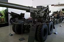
155 mm gun M1
The 155 mm gun M1 was a 155 millimeter caliber field gun developed and used by the United States military. Nicknamed "Long Tom" (an appellation with a long and storied history in U.S. field and naval artillery), it was produced in M1 and M2 variants, later known as the M59. Developed to replace the Canon de 155mm GPF, the gun was deployed as a heavy field weapon during World War II and the Korean War, and also classed as secondary armament for seacoast defense. The gun could fire a 100 lb (45 kg) shell to a maximum range of 14 mi (23 km), with an estimated accuracy life of 1,500 rounds.
| M1 155 mm Long Tom | |
|---|---|
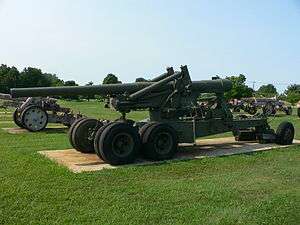 Long Tom in travelling position, US Army Ordnance Museum. | |
| Type | Towed field artillery |
| Place of origin | United States |
| Service history | |
| Used by | United States Italy Australia Greece Austria Japan Jordan South Korea Republic of China Turkey Pakistan Croatia South Africa United Kingdom Yugoslavia Netherlands |
| Wars | World War II, Korean war, Cambodian Civil War, Croatian War of Independence |
| Production history | |
| Designed | 1918–1938 |
| Produced | October 1940–June 1945 |
| No. built | 1,882 |
| Specifications | |
| Mass | Travel: 13,880 kg (30,600 lb) |
| Length | Travel: 11 m (36 ft 1 in)[1] |
| Barrel length | 6.97 m (22 ft 10 in) L/45 |
| Width | Travel: 2.5 m (8 ft 2 in)[1] |
| Height | Travel: 2.7 m (8 ft 10 in)[1] |
| Crew | 14 |
| Shell | Separate loading charge and projectile[1] |
| Caliber | 155 mm (6.10 in) |
| Breech | Asbury mechanism |
| Recoil | Hydro-pneumatic[1] |
| Carriage | M1 Carriage |
| Elevation | −2°/+65° |
| Traverse | 60° |
| Rate of fire | 40 rounds per hour |
| Muzzle velocity | 853 m/s (2,799 ft/s) |
| Maximum firing range | 23.7 km (14.7 mi) |
The Long Tom was also adopted by a number of other nations, including the United Kingdom, Austria, Israel, and the Netherlands.
Development
Before entering World War I, the United States was poorly equipped with heavy artillery. To address this problem a number of foreign heavy artillery guns were adopted, including the Canon de 155 mm GPF. After the end of the war the Westervelt Board was convened to assess the artillery experience of the combatant powers and map out future directions for the US Army artillery. The conclusion of the board vis-a-vis heavy field artillery was that the French 155mm GPF should be adopted as the standard heavy field piece but further development work should occur to achieve a heavy field gun with a max. range of 25,000 yards, a vertical arc of fire from 0° to 65°, a projectile not exceeding 100 lbs and the capability to be mounted on a caterpillar mount or a rubber tired towed mounting.[2] A number of prototypes were produced in the 1920s and 1930s, but the projects were put on hold due to lack of funds. In 1938 the 155 mm gun T4 on carriage T2 was finally adopted as 155 mm gun M1 on carriage M1.[3]
155 mm gun M1
The new gun design used a barrel similar to the earlier 155 mm GPF, but with an Asbury mechanism that incorporated a vertically-hinged breech plug support. This type of breech used an interrupted-thread breech plug with a lock that opened and closed the breech by moving a single lever.[4] The ammunition for the 155 mm gun was "separate-loading", that is with the shell and the powder charge packaged, shipped and stored separately. The shell is lifted into position behind the breech and then rammed into the chamber to engage the shell's rotating band into the barrel rifling.[5]
Ramming the shell home is followed by loading a number of powder bags, as required for the desired range.[6] The powder charge could be loaded in up to seven charge settings. Once the powder is loaded, the breech plug is closed and locked, and a primer is placed in the breech plug's firing mechanism. After setting the elevation and azimuth, the gun is ready to fire. The firing mechanism is a device for initiating the ammunition primer. The primer then sets off the igniter which ignites the propelling charge of the ammunition. A continuous-pull lanyard first cocks the firing pin, then fires the primer when pulled.[7]
The gun was developed into M1A1 and M2 variants. After World War II, the United States Army re-organized, and the gun was re-designated as the M59.
Carriage M1
The gun carriage provides a stable, yet mobile, base for the gun. The new split-trail carriage featured an eight-wheel integral two-axle bogie and a two-wheel limber that supported the trails for transport. The carriage was a two-piece design. The upper carriage included the side frames with trunnion bearings that supported the recoil mechanism that carried the gun cradle, slide and gun tube. The upper carriage also incorporated the elevating and azimuth gearing. The upper carriage pivoted in azimuth on the lower carriage. The lower carriage included the transport suspension and the split-trail that stabilized and absorbed recoil when the gun was fired.[8]
After the gun was placed in a firing position with the gun pointing in the desired direction, the trails were lowered to the ground and the limber was removed. The carriage wheels would then be raised using built-in ratcheting screw-jacks, lowering the gun carriage to the ground. Once on the ground, the limber-end of the trail legs were separated to form a wide "vee" with its apex at the center of the carriage pivot point. A recoil spade at the limber-end of each trail leg required a correctly positioned hole to be dug for the spade, which was attached to the trail end, to transmit the recoil from gun carriage through the trails and into the earth. This made the gun very stable and assisted its accuracy. The removable spades were transported in brackets on the trail legs.[9]
The carriage M1 and M2 were shared with the 8 inch Howitzer M1, differing only in the gun tube, sleigh, cradle, recoil and equilibrators, weight due to the heavier barrel.[10]
| Bottom carriage | Top carriage |
|---|---|
| Firing support base | Elevating mechanism |
| Trails | Traversing mechanism |
| Retractable suspension system | Gun support components |
| Axle | Equilibrator[12] |
| Brakes | Cradle (Connects gun assembly to the top carriage) |
| Wheels | Recoil mechanism |
| Sleigh (Sliding support for the gun tube) | |
| Gun tube |
Specifications
| Weight of gun (complete with breech mechanism) | 9,595 lb (4,352 kg) |
| Weight of tube assembly (barrel) | 9,190 lb (4,169 kg) |
| Length of tube | 277.37 in (7.05 m) |
| Length of bore | cal. 45 (274.6 in / 6.975m) |
| Length of rifling | 230.57 in. |
| Powder pressure (normal pressure with maximum charge in a new gun) | 40,000 psi (275,790 kPa) |
| Type of breechblock | Interrupted screw |
| Weight of breech mechanism | 405 lb (184 kg) |
| Type of firing mechanism | continuous pull percussion hammer |
Service
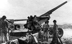
The Long Tom saw combat for the first time in the North African Campaign on December 24, 1942, with "A" Battery of the 36th Field Artillery Battalion. Eventually it equipped about 49 battalions, including 40 in the European Theater and 7 in the Pacific. It was used by several Marine defense battalions, notably during Operation Cartwheel in 1943.
The preferable prime mover was initially the Mack NO 6×6 7½ ton truck; from 1943 on it was supplemented by the tracked M4 High Speed Tractor.[13]
A small number of Long Tom guns were authorised for supply via lend lease channels, to the United Kingdom (184) and France (25).[14] The authorised establishment of British batteries (excluding training units), including four batteries from the Dominion of Newfoundland, totalled 88 guns.
Variants
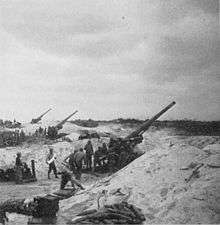
Gun variants:
- M1920 – prototype.
- T4 – prototype.
- M1 (1938) – first production variant, 20 built.
- M1A1 (1941) – modified breech ring.
- M1A1E1 – prototype with chromium-plated bore.
- M1A1E3 – prototype with liquid cooling.
- M2 Standard (1945) – with modified breech ring.
Carriage variants:
- T2 – prototype.
- M1 (1938).
- M1A1 – refurbished T2 carriages.
- M2 Standard
Limber variants:
- M1 Standard (1938)
- M5 Heavy (1945)
The gun was also mounted on a modified M4 medium tank chassis, in mount M13. The resulting vehicle was initially designated 155 mm Gun Motor Carriage T83 and eventually standardized as 155 mm Gun Motor Carriage M40.[15] 155 mm Gun Motor Carriage T79, based on T23 Medium Tank chassis, never advanced past proposal stage.[16] A portable "Panama mount" M1 was also provided.
Ammunition
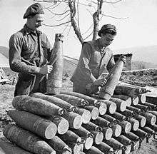
The gun utilized separate loading, bagged charge ammunition. The propelling charge consisted of base (9.23 kg) and increment (4.69 kg). The data in the table below is for supercharge (base and increment).
| Type | Model | Weight | Filler | Muzzle velocity | Range |
|---|---|---|---|---|---|
| APBC/HE | AP M112 Shell | 45.36 kg (100.0 lb) | Explosive D | 2746 ft/s (837 m/s) | 24,075 yds (22,014 m) |
| HE | HE M101 Shell | 42.96 kg (94.7 lb) | TNT | 2800 ft/s (853 m/s) | 25,714 yds (23,513 m) |
| Smoke | WP M104 Shell | 44.53 kg (98.2 lb) | White phosphorus (WP) | 2800 ft/s (853 m/s) | 25,940 yds (23,720 m) |
| Smoke | FS M104 Shell | Sulfur trioxide in chlorosulfonic acid | 2800 ft/s (853 m/s) | 25,940 yds (23,720 m) | |
| Chemical | H M104 Shell | Mustard gas, 5.3 kg (12 lb) | 2800 ft/s (853 m/s) | 25,940 yds (23,720 m) | |
| Dummy | Dummy Mk I Projectile | – | – | – | |
| Dummy | Dummy M7 Projectile | 43.09 kg (95.0 lb) | – | – | – |
| Armor penetration, mm[15][19][20] | ||||
| Distance | ||||
|---|---|---|---|---|
| Ammunition | 457 m (500 yd) |
914 m (1,000 yd) |
1,371 m (1,500 yd) | |
| AP M112 Shell (homogeneous armor, meet angle 30°) | 160 | 152 | ||
| AP M112 Shell (face hardened armor, meet angle 30°) | 135 | 130 | ||
| AP M112 Shell (homogeneous armor, meet angle 0°) | 193 | 191 | 183 | |
| Concrete penetration, mm[15] | ||||
| Ammunition | 914 m (1,000 yd) | 4,572 m (5,000 yd) | ||
| HE M101 Shell (meet angle 0°) | 2,011 | 1,402 | ||
| Different methods of measurement were used in different countries / periods. Therefore, direct comparison is often impossible. | ||||
Existing examples
Pakistan
- Pak Army Museum Rawalpindi in best Form (Near M41 Patton Medium Tank) Outdoor Exhibits.http://www.pakarmymuseum.com/galleries/outdoor/
Austria
- Bunkermuseum Wurzenpass, Wurzen Pass (near Villach)[21]
Australia
- Fort Lytton Military Museum, Brisbane.[22]
Israel
- Batey ha-Osef Museum, Tel Aviv, Israel[23]
Germany
- Grafenwoehr Training Area - this particular cannon is apparently a return from Italy, based on Italian language markings added, and old Pirelli tires.
Netherlands
- Wings of Liberation Museum Park in Best (near Eindhoven), Netherlands [24]
United Kingdom
- Pendennis Castle, Cornwall, UK
- Royal Armouries, Fort Nelson, Hampshire, UK
- Muckleburgh Military Collection, Norfolk, UK
United States
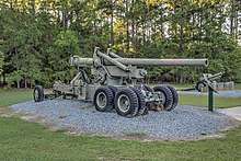
- Battleship Memorial Park, Mobile, Alabama
- Timber Linn Park, Albany, Oregon, see an aerial photo on Google Maps
- US Army Ordnance Museum, Aberdeen, Maryland
- VFW Zachary Taylor Post 3784, Baton Rouge, Louisiana.
- Georgia Veterans Memorial State Park, Cordele, Georgia
- Fort Sill Field Artillery Museum, Fort Sill, Oklahoma
- Iowa Gold Star Military Museum, Camp Dodge, Johnston, Iowa
- VFW Post 2330, Searcy, AR
- Museum of American Armor, Old Bethpage, New York
- Scotland Meadows Park, New Castle, Pennsylvania
- General George Patton Museum and Center of Leadership, Fort Knox, Kentucky.
- VFW Post 61, Kansas City, MO
- Flying Heritage & Combat Armor Museum, Everett, WA
- Watervliet Arsenal, Watervliet, NY
See also
- List of U.S. Army weapons by supply catalog designation SNL D-24
- 15 cm Kanone 18 German equivalent
- 152 mm gun M1935 (Br-2) Soviet equivalent, built only in small numbers
- Cannone da 149/40 modello 35 Italian equivalent, only few built
Notes
- Foss, Christopher (1977). Jane's pocket book of towed artillery. New York: Collier. p. 135. ISBN 0020806000. OCLC 911907988.
- http://morrisswett.contentdm.oclc.org/cdm/singleitem/collection/p15766coll2/id/529/rec/1 The Report of the Westervelt Board 1919 p 29-31
- TM 9-3305 p 2-8, Figure 2-12, M1 155-mm gun on M2 (Long Tom) carriage.
- "Breachblock". Archived from the original on 2013-02-08. Retrieved 2012-12-19.
- TM 9-3305 p 5-1, Figure 5-2, Hand loading and ramming for weapons firing separate-loading ammunition
- TM 9-3305 p 4-1, Figure 4-2. Lands and grooves and Figure 4-3. Projectile with rotating band.
- TM 9-3305 p 4-15, Figure 4-27 M13 firing mechanism.
- TM 9-3305 p 7-2, Figure 7-1, Top and bottom carriages.
- Popular Science Magazine
- TM 9-3305 p 2-11, Figure 2-18. M1 8-inch howitzer on M1 (M1 5) carriage.
- TM 9-3305 p 7-3, Figure 7-2, gun support assembly.
- TM 9-3305 p 7-7, Figure 7-6. Pneumatic equilibrator.
- Zaloga – US Field Artillery of World War II, pp. 20–22.
- Zaloga, US Field Artillery of World War II, p. 37.
- Hunnicutt – Sherman: A History of the American Medium Tank, p 353-355, 570.
- Hunnicutt – Pershing, A History of the Medium Tank T20 Series, p 158.
- Technical Manual TM 9-1901, Ammunition, p 197-202.
- Technical Manual TM 9-1904, Ammunition Inspection Guide, p 490-518.
- http://www.90thidpg.us/Reference/Manuals/FM%206-40.pdf
- http://www.ibiblio.org/hyperwar/USA/ref/TM/pdfs/TM9-1901.pdf
- http://www.bunkermuseum.at/
- "155mm Long Tom Gun | Fort Lytton Historic Military Precinct". fortlytton.org.au. Retrieved 13 August 2016.
- File:PikiWiki Israel 32427 Israel Defense Forces.JPG
- File:Museum Bevrijdende Vleugels 3.JPG
References
- Bishop, Chris (1998). Encyclopedia of Weapons of World War II. ISBN 0-7607-1022-8.
- Hunnicutt, R. P. (1994). Sherman: A History of the American Medium Tank. Presidio Press. ISBN 0-89141-080-5.
- Hunnicutt, R. P. (1996). Pershing, A History of the Medium Tank T20 Series. Feist Publications. ISBN 1-112-95450-3.
- Williford, Glen M (2016). American Breechloading Mobile Artillery 1875-1953. Thomas D. Batha. Schiffer Publishing Ltd. ISBN 978-0-7643-5049-8.
- Zaloga, Steven J. (2007). US Field Artillery of World War II. New Vanguard 131. illustrated by Brian Delf. Osprey Publishing. ISBN 978-1-84603-061-1.
- Hunnicutt, R. P. (1996). Pershing, A History of the Medium Tank T20 Series. Feist Publications. ISBN 1-112-95450-3.
- Technical Manual TM 9-350, 155-MM Gun M2; Carriage Ml AND M1A1; Gun Mount M13; Heavy Carriage Limber M2 AND M5; AND Firing PlatformM Ml. War Department, 1944.
- Technical Manual TM 9-1901, Artillery Ammunition. War Department, 1944.
- Technical Manual TM 9-1904, Ammunition Inspection Guide. War Department, 1944.
- Technical Manual TM 9-3305, Principles of Artillery Weapons. Department of the Army, May 1981.
- Field Manual FM 6-40, Field Artillery Gunnery. War Department, June 1945.
External links
| Wikimedia Commons has media related to M1 Long Tom 155 mm gun. |
- 155-mm. Novel Mechanical Features Give Big-Gun Power, Small Gun Speed, November 1942, Popular Science early article with many photos and detailed drawings showing how it is brought into firing position from travel mode.
