Introduction

This repair guide was authored by the iFixit staff and hasn’t been endorsed by Google. Learn more about our repair guides here.

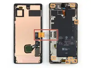
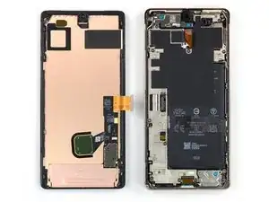
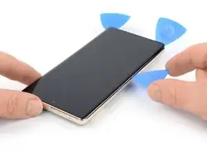
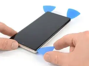
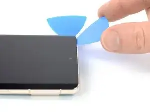
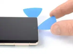
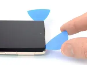
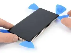
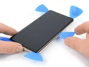
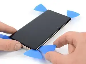
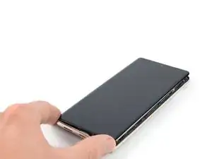
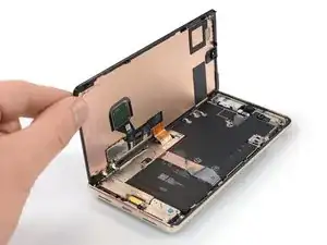
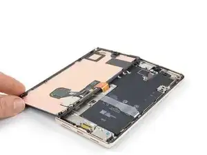
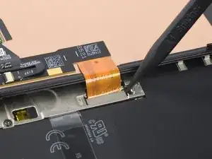
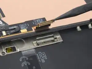
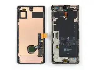
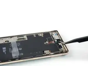
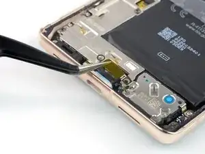
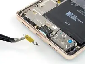
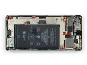
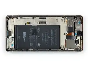
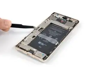
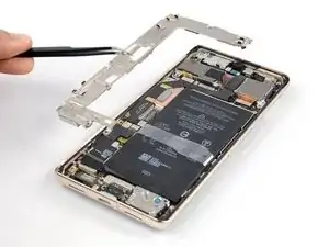
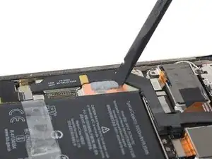
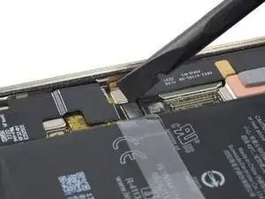
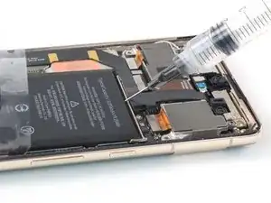
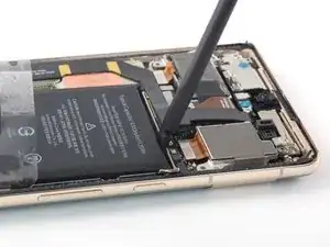
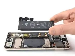
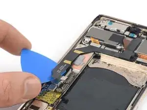
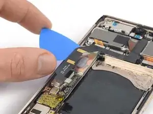
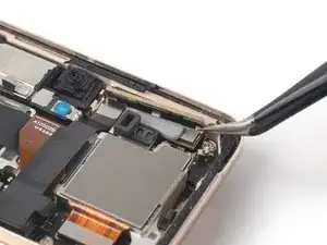
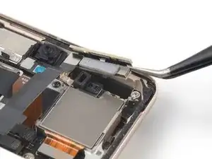
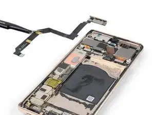
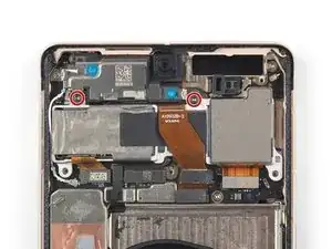
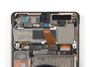
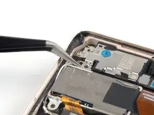
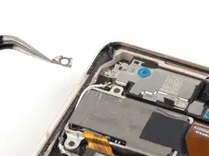
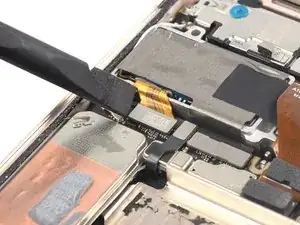
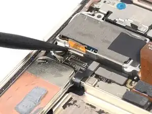
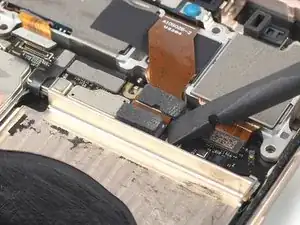
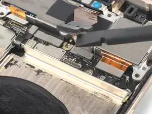
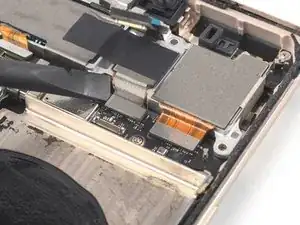
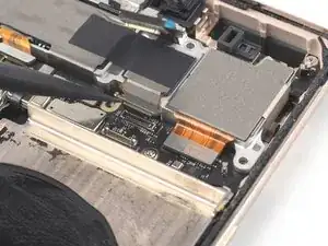
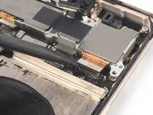
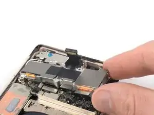
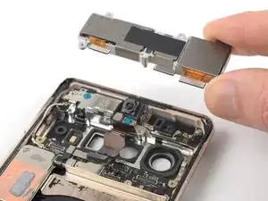
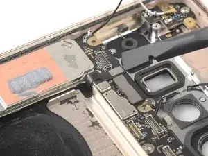
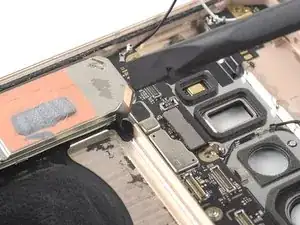
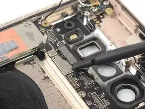
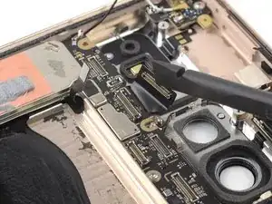
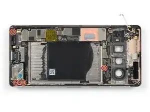
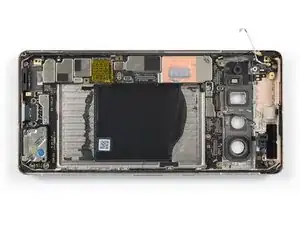
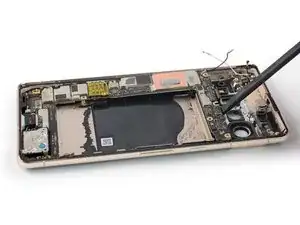
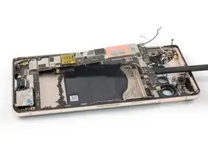
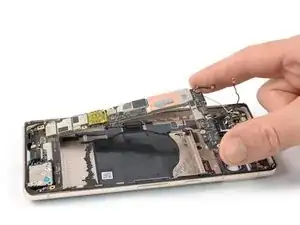
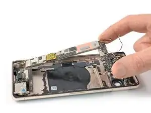
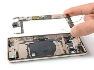
Use this guide to replace the loudspeaker in your Google Pixel 7 Pro. The loudspeaker is tucked underneath the motherboard and requires substantial disassembly in order to remove it.

This guide was made using the GE2AE model, which features a 5G mmWave antenna. If you have a non-mmWave model, you can still use this guide—just ignore the mmWave antenna steps.

For your safety, discharge the battery below 25% before disassembling your phone. This reduces the risk of fire if the battery is accidentally damaged during the repair. If your battery is swollen, take appropriate precautions.

Caution: The Pixel 7 Pro contains class 1 lasers. Disassembly could result in exposure to invisible infrared laser emissions.

Retaining water resistance after the repair will depend on how well you reapply the adhesive, but your device will lose its IP (Ingress Protection) rating.

You'll need replacement adhesive in order to complete this repair.

  1. pcCOWHCOgiE1OqGw
    pcCOWHCOgiE1OqGw
    jJUWoaZ3KpXfhiPF
    • Allow your battery to drain below 25% before starting this repair. A charged battery may catch fire if damaged.

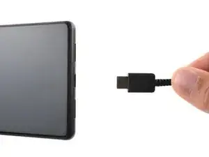
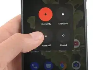
    • Fully power off your phone and unplug any cables.

  2. r4cF1OLmMUoCTLb3
    r4cF1OLmMUoCTLb3
    rWVVVxdKliEb2ajr
    GupbaQq5eGmqFscR
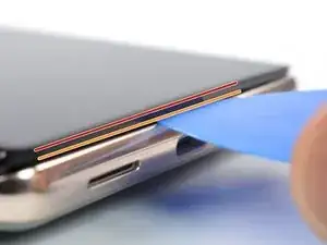
    • The screen of the Google Pixel 7 Pro is held in place by plastic clips and adhesive. Note the following:

    • Screen seam: This seam separates the screen from the rest of the phone. Do not pry at this seam.

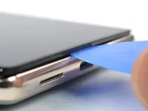
    • Bezel seam: This is where the plastic bezel designed to protect the screen meets the frame. It's held in place by plastic clips. This is where you should pry.

    • During the removal procedure, make sure to insert your opening picks in the right position to avoid separating the screen from its safety frame.

    • Only insert the pick up to ~3.5 mm during the removal procedure to avoid damaging the internals and to avoid interfering with the plastic clips.

    • There are several plastic clips around the whole screen. If your opening pick gets blocked during the screen removal procedure, you've inserted your pick too deep underneath the screen.

    About the paragraph:

    During the removal procedure, make sure to insert your opening picks in the right position to avoid separating the screen from its safety frame.


    It was not clear to me what the safety frame was until I opened the phone; I was careful but while opening the phone I slid a pick between the screen and the frame, and they became separated in one corner, I wonder if this resulted to my screen being damaged after the repair.

    An image that shows what the security frame is would be helpful.

    Eduardo CGZ -

    It is VERY difficult to get an angle into the frame and under the plastic bezel. Since this repair is for a screen, you don't have to worry about damaging it further because you will. I've done dozens of these repairs and have gotten ONE removed without further damage. Just an FYI. I also use 91% alcohol around the edges off the frame as well as heat (I have a hot plate set at 80*c that I lay it on after adding alcohol around the edges, place on hot plate for about 10 minutes, add more alcohol around the edges and then place on hot plate for another 5 minutes).

    Gregg Stanley -

    Thank you so much for the info about the degrees, amount of time, and when to apply alcohol! I really needed this info!!! Hallelujah!!

    Rachel Kelley -

  3. AYwHUCCnKa1PMPBk
    AYwHUCCnKa1PMPBk
    yNNd3VhQocdUMaOI
    SCh6OtwmLUCIn5j1
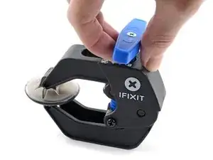
    • The next three steps demonstrate the Anti-Clamp, a tool we designed to make the opening procedure easier. If you aren't using the Anti-Clamp, skip down three steps for an alternate method.

    • For complete instructions on how to use the Anti-Clamp, check out this guide.

    • If your screen is cracked, cover it with a layer of clear packing tape to help the suction cup adhere.

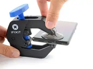
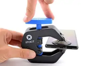
    • Pull the blue handle backwards to unlock the Anti-Clamp's arms.

    • Slide the arms over either the left or right edge of your phone.

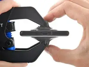
    • Position the suction cups near the bottom edge of the phone—one on the front, and one on the back.

    • Squeeze the cups together to apply suction.

    • If you find that the surface of your phone is too slippery for the Anti-Clamp to hold onto, you can use tape to create a grippier surface.

    The pixel 7 pro kit does not come with the clamp and may have to be purchased separately

    juji juman -

  4. s4bXrPEIrDSclUY1
    s4bXrPEIrDSclUY1
    xOmcoIQRPcMiuOrf
    trhAAYQPS13QxU3X
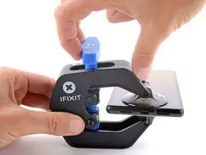
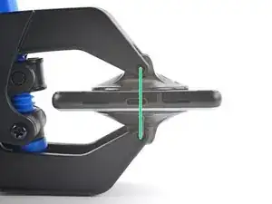
    • Pull the blue handle forward to lock the arms.

    • Turn the handle clockwise 360 degrees or until the cups start to stretch.

    • Make sure the suction cups remain aligned with each other. If they begin to slip out of alignment, loosen the suction cups slightly and realign the arms.

  5. qnrEDsCQlNx3INRF
    qnrEDsCQlNx3INRF
    YdcsV4CGCCD2YxkZ
    HuaYDv3YNjHEvN5X
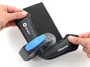
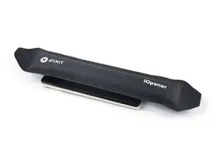
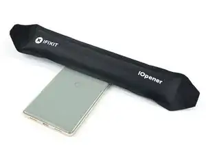
    • Heat an iOpener and thread it through the arms of the Anti-Clamp.

    • You can also use a hair dryer or heat gun—but extreme heat can damage the display and/or internal battery, so proceed with care.

    • Fold the iOpener so it lays on the bottom edge of the phone.

    • Wait one minute to give the adhesive a chance to release and present an opening gap.

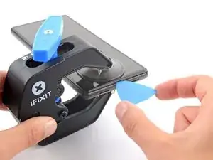
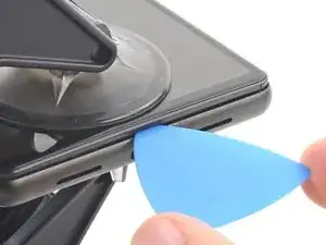
    • Insert an opening pick under the screen frame when the Anti-Clamp creates a large enough gap.

    • If the Anti-Clamp doesn't create a sufficient gap, apply more heat to the area and rotate the handle clockwise half a turn.

    • Don't crank more than a half a turn at a time, and wait one minute between turns. Let the Anti-Clamp and time do the work for you.

    • Skip the next two steps.

  6. kYIPqvhXCJ1NBLIi
    • Apply a heated iOpener to the screen to loosen the adhesive underneath. Apply the iOpener for at least 3 minutes.

    • A hair dryer, heat gun, or hot plate may also be used, but be careful not to overheat the device. The edge should feel slightly too hot to the touch.

  7. PeNGZEHQUUUXVT1r
    PeNGZEHQUUUXVT1r
    L4JtimoXTuDctFTG
    JIGomFFqcX2UFdaU
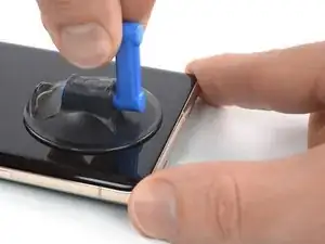
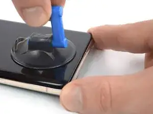
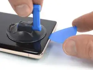
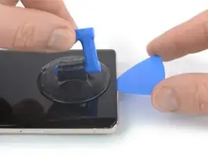
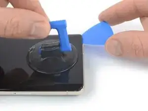
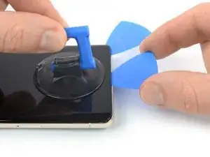
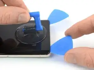
    • Once the screen is warm to the touch, apply a suction handle to the bottom edge of the screen.

    • If your display is badly cracked, covering it with a layer of clear packing tape may allow the suction cup to adhere. Alternatively, very strong tape may be used instead of the suction cup. If all else fails, you can superglue the suction cup to the broken screen.

    • Lift the screen including its safety frame with the suction handle to create a small gap between the screen and the phone assembly.

    • Depending on the age of your phone, this may be difficult. If you're having trouble, apply more heat to the bottom edge and try again.

    • Insert an opening pick into the gap.

    The crack on my screen is along the bottom, on a diagonal. I cannot get the suction cup to lift off the edge. I've tried more heat using a hair dryer, using tape, but nothing seems to work! The phone is only a few months old, could that be the issue? I'm really frustrated after trying multiple times throughout the day today.

    AMB -

    I’m having the same issue unfortunately. I’ve superglued the suction cup and have it under weight. Going to wait 24 hours to see if it helps. Without a proper seal, there’s no way it’s going to lift. I made sure to leave about a half inch gap from the bottom of the phone to try and use the warming pad one more time

    Claudio Sandoval -

  8. WtsW1wWeNrRMUTmr
    WtsW1wWeNrRMUTmr
    IGkvmFQmLJALAeSW
    • To avoid damaging your phone, don't insert your pick more than ~2.5 mm as you separate the screen adhesive. Note the following areas:

    • The screen cable is a little less than halfway up the left edge of the phone. Be very careful here to avoid tearing the cable.

    • There are many spring contacts around the perimeter of the phone. Be very careful in these areas to avoid bending the contacts.

  9. omlR6Jkq43Lt3Vp4
    omlR6Jkq43Lt3Vp4
    eaXnOrF2qrKe5EPi
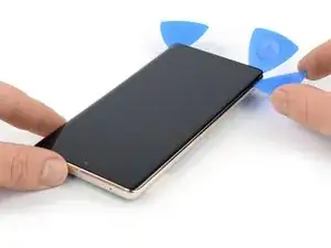
    • Slide the opening pick to the bottom right corner of the screen to slice its adhesive.

    • Leave the opening pick in place to prevent the adhesive from resealing.

    is there any top speaker grill/mesh on Pixel 7 pro?

    Mostafa Kamel -

  10. 4NQTIvBDbIAyxkFV
    4NQTIvBDbIAyxkFV
    yR5ymuvShRAeDLVc
    • Insert a second opening pick at the bottom edge and slide it to the bottom left corner of the screen to slice the adhesive.

    • Leave the opening pick in place to prevent the adhesive from resealing.

    • There's a plastic clip in the bottom left corner that will block your opening pick. Only use the tip of the opening pick (~1 mm) to work your way around it.

  11. tArTDTqN2LK6GhId
    tArTDTqN2LK6GhId
    5vMVYYuPuERQHXqy
    JACYuENUqUA5bvoW
    • Insert a third opening pick underneath the bottom left corner of the screen.

    • Slide the opening pick along the left edge of the screen to slice the adhesive and to release the plastic clips.

    • Leave the opening pick in the top left corner to prevent the adhesive from resealing.

  12. UO6jX5pnbY321YRC
    UO6jX5pnbY321YRC
    5PtIvBbaZ6bIQCI4
    UoguGE13LKwywumV
    • If the adhesive becomes hard to cut, it has most likely cooled down. Use your iOpener or heat gun for 1-2 minutes to reheat it.

    • When you slice near the front facing camera, insert only the tip of the opening pick (~2.5 mm) to avoid damaging or smearing the camera.

    • Insert a fourth opening pick at the top left corner of the screen.

    • Slide the opening pick along the top edge of the phone to slice the adhesive.

    • Leave the opening pick in the top right corner to prevent the adhesive from resealing.

  13. l5pYkUOOVLpkPl32
    l5pYkUOOVLpkPl32
    VIiGmqFDhmZJ4FWT
    mBm34rSKijkgG25V
    • Insert a fifth opening pick and slide it along the right edge of the phone to slice the remaining adhesive and release the right plastic clips.

    • Do not try to remove the display all the way yet, the screen is still connected to the phone assembly by a flex cable.

  14. cyGRQp6UwNmhnB6T
    cyGRQp6UwNmhnB6T
    vCf5HqyX2FKfIAtt
    EbGcFSX5cdP3PrlN
    • Lift the right edge of the screen up and towards the left side of the device, like opening a book.

    • Don't twist the screen or move it too far away from the frame to avoid straining or damaging the flex cable.

    • Rest the screen upside down and parallel to the frame.

  15. EqZdPNUuC5LFAgRG
    EqZdPNUuC5LFAgRG
    nIvkgQ5cQZSCZTSV
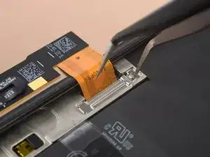
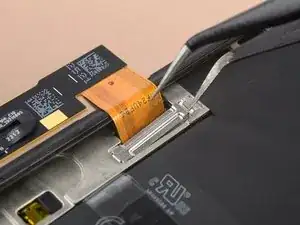
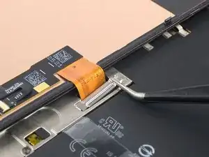
    • The display cable bracket sits tightly and requires some force to release it.

    • Insert one arm of a pair of tweezers into the opening at the upper end of the display cable bracket.

    • Push the bracket inwards and pry up to release it.

  16. ZT2CSWdPIEV36jbJ
    ZT2CSWdPIEV36jbJ
    upn1sPjlWOBlBlMw
    G5TJqWF6l1rpJXZ5
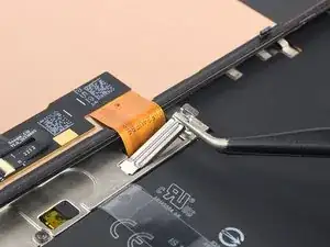
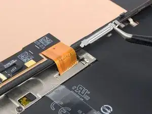
    • Use a pair of tweezers to remove the display cable bracket by pulling it from underneath the midframe and in direction of the camera.

  17. hkaumpj4K3uXMnUD
    hkaumpj4K3uXMnUD
    1uXl52GPnG6yFc5W
    • Use a spudger to disconnect the display flex cable by prying the connector straight up from its socket.

    • To re-attach press connectors like this one, carefully align and press down on one side until it clicks into place, then repeat on the other side. Do not press down on the middle. If the connector is misaligned, the pins can bend, causing permanent damage.

  18. HkQ5APLLBpQ1rYoO
    • Separate the screen from the phone assembly.

    • During reassembly:

    • Check that all screws are tightened and there are no loose parts.

    • Reconnect the screen and test your phone to make sure it works. Power it back down and continue reassembly.

    • Apply new adhesive where it's necessary after cleaning the relevant areas with isopropyl alcohol (>90%).

    • Follow this guide if you're using custom-cut adhesives for your device.

    • Follow this guide in case you're using a pre-cut adhesive card.

    • During the boot-up process after reassembly, the screen will go through a calibration sequence. Do not touch the screen during this process, as it could result in improper touch calibration and create touch issues.

  19. nXYOwlLBgvLJ16iD
    nXYOwlLBgvLJ16iD
    2Hm2iRdXQJJqYbNI
    eFTFHmmkrli1AEEf
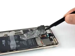
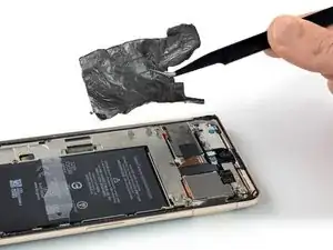
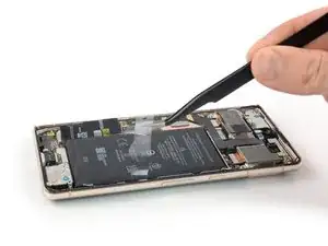
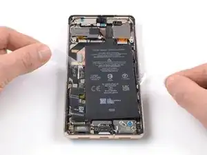
    • Use a pair of tweezers to carefully peel the graphite foil off the battery and midframe.

    • Take care not to puncture or bend the battery with your tool—a punctured or bent battery may leak dangerous chemicals or cause a fire.

    • If you're having a hard time peeling off the foil, you can apply a heated iOpener to the back of the device for two minutes to loosen its adhesive.

  20. kEAnP3LhyqG2XCbR
    kEAnP3LhyqG2XCbR
    NNP3gIXnDXyOJbVT
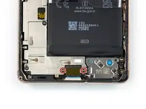
    • Use a Torx T3 screwdriver to remove the two 5.1 mm-long screws securing the charging port bracket.

  21. oNFQELvyr2PiW4yR
    oNFQELvyr2PiW4yR
    el1BY4C1Fn4J3IZ3
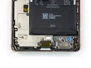
    • Use a pair of tweezers to remove the charging port bracket.

  22. PkVakKpIwCmud6Uj
    PkVakKpIwCmud6Uj
    O64uByMxYEjqC6K2
    • Use a Torx T3 screwdriver to remove the six 5.1 mm-long screws securing the midframe.

  23. LPYTmDdYNLsMUFZl
    LPYTmDdYNLsMUFZl
    PLfGV2OreelDKjBM
    Un4YRHOSKkiltkKV
    • Use a pair of tweezers to remove the midframe.

    • During reassembly check the condition of the thermal pad. If it's damaged, remove the pad, clean the area with high-concentration (greater than 90%) isopropyl alcohol and a microfiber or lint-free cloth, and apply a new thermal pad.

  24. Ot356CyM5TfqUKbU
    Ot356CyM5TfqUKbU
    3wPAZEdMLKGCqdxR
    • Use a spudger to disconnect the battery cable by prying the connector straight up from its socket.

  25. 2Rk6GPhHJWkcsmD3
    • Apply a heated iOpener to the back of the device to loosen the adhesive underneath. Apply the iOpener for at least 3 minutes.

    • A hair dryer, heat gun, or hot plate may also be used, but be careful not to overheat the device. The edge should feel slightly too hot to the touch.

  26. 14Z3oBdXSMiNtCTf
    14Z3oBdXSMiNtCTf
    JOda5htTYVw3Sygi
    cVSYADaU4UTpsMRS
    • Use tweezers, or your fingers, to peel the plastic pull tabs away from the battery.

  27. tAyyeJ4FKcvcAFbg
    tAyyeJ4FKcvcAFbg
    dAiaDEAKMwMJOHtb
    XSTPwFrRaMcEdaOC
    • Pull the tabs back and forth in a sawing motion up the length of the battery to separate the adhesive underneath.

    • Work slowly. It's easy to lose your grip and accidentally pull the tab up from under the battery.

    • If you're having difficulty separating the adhesive, apply more heat and wait for the adhesive to loosen.

    • If you lose or tear the release strip, follow the next step for an alternative battery removal method.

  28. iThCtM6iFagiG6u2
    iThCtM6iFagiG6u2
    ELEiTR2PCFUgKnJn
    GeUCdIPHWZE2eQlU
    • Follow this step if you couldn't loosen the battery using the battery release strip.

    • Apply a few drops of high concentration (90% or higher) isopropyl alcohol into the gap at the top edge of the battery.

    • Don't apply too much alcohol, or you'll loosen the NFC antenna and charging coil underneath the battery.

    • Wait about one minute for the alcohol solution to weaken the adhesive.

    • Use the flat end of a spudger or an opening pick to gently lift the top edge of the battery until you can grab it with your fingers.

    • Don't use excessive force on the battery. Slow, consistent pressure is all that's required to free it from the frame.

    • Take care not to puncture or bend the battery with your tool—a punctured or bent battery may leak dangerous chemicals or cause a fire.

  29. ZXcFqioFxBeXmxaK
    ZXcFqioFxBeXmxaK
    ngPHUiTlBbZZLTIg
    • Tilt the battery out of the device to separate the rest of the adhesive.

    • Remove the battery.

    • Do not reinstall a damaged or deformed battery, as doing so is a potential safety hazard.

    • To secure the replacement battery:

    • Apply pre-cut adhesive adhesive or double-sided tape to the battery well at the places where the old adhesive was located, not directly onto the battery.

    • Temporarily reconnect the battery to the motherboard to help align it correctly. Disconnect the battery after it's seated.

    • Make sure that the battery sits in the center of the battery well and there's an even gap around the battery.

    • Press the new battery firmly into place.

  30. 3aVGuAbbFZycLuDA
    3aVGuAbbFZycLuDA
    fFayZ1hfO6Ml6IAF
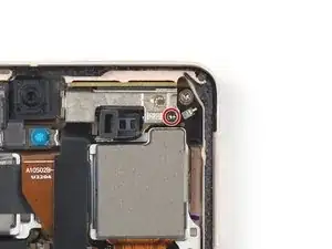
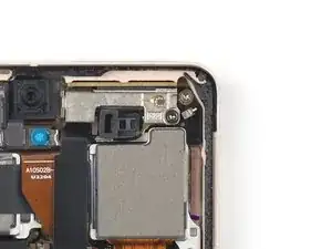
    • Use a Torx T3 screwdriver to remove the 5.1 mm-long screw securing the mmWave antenna bracket.

  31. iyUaHVAxfdDis5s3
    iyUaHVAxfdDis5s3
    QQFHGF5ZxuqVqkQu
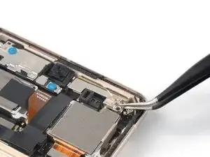
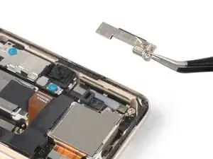
    • Use a pair of tweezers to remove the mmWave antenna bracket.

  32. c1vCWsYPKx1JA2AG
    c1vCWsYPKx1JA2AG
    DUlwdOmnIWbMdW25
    • Use a spudger to disconnect the mmWave antenna cable by prying the connector straight up from its socket.

  33. nY5nEEbPqeBJDg3P
    nY5nEEbPqeBJDg3P
    QUaOW4GCdZOlykNP
    UT5DXYXRr41QXJdX
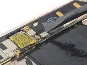
    • The mmWave antenna cable is held in place by mild adhesive.

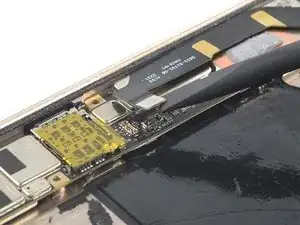
    • Slide an opening pick underneath the mmWave antenna cable starting at its bottom end.

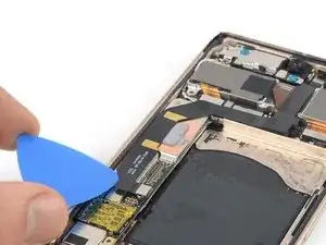
    • Use the opening pick to separate the mmWave antenna cable from the motherboard.

  34. yAQQySaWPQDvVEHK
    yAQQySaWPQDvVEHK
    oixDfROEAeEthH3R
    GjNF2U2HBS1CdPvn
    • Use a pair of tweezers to lift the mmWave antenna including its cable out of its recess.

    • Remove the mmWave antenna assembly.

  35. dAFPsVOexjEiDYDy
    dAFPsVOexjEiDYDy
    k3XfrqMHltGHrUeT
    ldYxiDTmtkdUQH3C
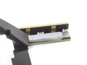
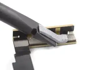
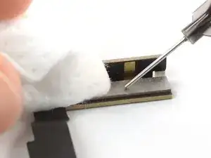
    • Use the flat end of a spudger to scrape the thermal paste off the mmWave antenna.

    • Clean any remaining thermal paste with isopropyl alcohol and either a coffee filter or a lint-free cloth.

    • Repeat the cleaning process for the thermal paste on the mmWave antenna bracket.

    • During reassembly, follow this guide for reapplying thermal paste onto the mmWave antenna.

  36. hGt3dbWUZgudmENt
    hGt3dbWUZgudmENt
    IAqLs5QBZUDKI51p
    • Use a Torx T3 screwdriver to remove the two 5.1 mm-long screws securing the rear camera assembly.

  37. JcJPeYhSiygfLD4B
    JcJPeYhSiygfLD4B
    VZvBJ1rDleXgNN4j
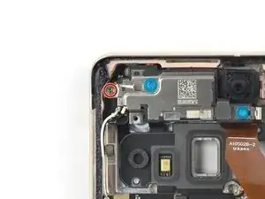
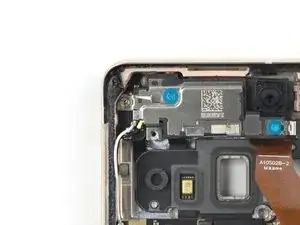
    • Use a pair of tweezers to remove the spring at the top left corner of the rear camera assembly.

  38. dmDDWTVIRJxi6lXe
    dmDDWTVIRJxi6lXe
    Tlp1trtaUQRwrsxH
    • Use a spudger to disconnect the telephoto camera cable by prying the connector straight up from its socket.

  39. vHsoEFSeBGDBk5sF
    vHsoEFSeBGDBk5sF
    VVaqPDoRK2gAjqOX
    • Use a spudger to disconnect the front facing camera cable by prying the connector straight up from its socket.

    • Fold the cable upwards to free the rear camera assembly.

    • Do not fold the cable sharply and only bend it to avoid cable damage.

  40. CbZC4EcmkTwp2tF2
    CbZC4EcmkTwp2tF2
    DuiadQMnULE3JWNY
    nGsR4CAtFAyZaus3
    • Use a spudger to disconnect the wide and ultrawide camera cables by prying the connectors straight up from their sockets.

  41. hJGLDM2ZTcsRnaeV
    hJGLDM2ZTcsRnaeV
    OFeaGdBQ11Odo3XU
    • Remove the rear camera assembly.

  42. LjJdZZDcq1WWGEsC
    LjJdZZDcq1WWGEsC
    lRmZXNshndJUKVb6
    • Use a Torx T3 screwdriver to remove the 3.1 mm-long screw securing the earpiece speaker.

  43. 5sEBgqIxMSXh4atG
    • Apply a heated iOpener to the camera glass to loosen the adhesive underneath the earpiece speaker. Apply the iOpener for at least 1 minute.

  44. VZLQl3glPVtBo2fg
    VZLQl3glPVtBo2fg
    jFpGhRLXXBoCbGDL
    • Insert the pointed end of a spudger between the top left corner of the earpiece speaker and the frame.

    • Pry upwards to loosen the earpiece speaker.

  45. yksYddqeIqQ63YKr
    yksYddqeIqQ63YKr
    EnPXUPbUL1DIdQmx
    • Use a pair of tweezers to remove the earpiece speaker.

  46. c56Uho6GHTSrIljH
    c56Uho6GHTSrIljH
    UHbrNV4wCdHlEtOE
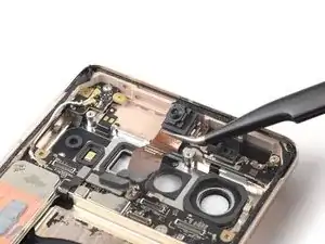
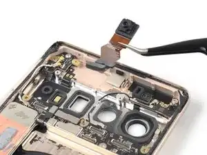
    • Use a pair of tweezers to remove the front facing camera.

  47. smT6LSEg5OqbwFgs
    smT6LSEg5OqbwFgs
    JoCMS2LkuyxtREHK
    TDHZea5Nn16KjPue
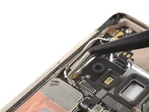
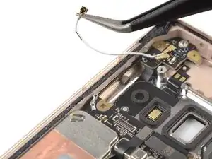
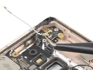
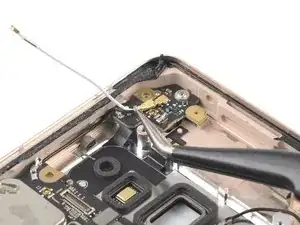
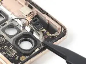
    • Use tweezers to grasp the white antenna cable connector at the top left corner of the motherboard.

    • Grasp the cable as close to the connector as possible to avoid damaging the connector.

    • Lift the coaxial connector straight up to disconnect the white antenna cable.

    • Use your tweezers to carefully loosen the cable from the retaining clips.

  48. kBLqF2XRs1mpmvPR
    kBLqF2XRs1mpmvPR
    2NcYJscr4rqqxO3d
    aD2mjNkUP2aQRnDd
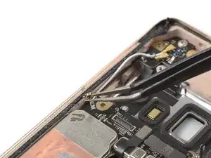
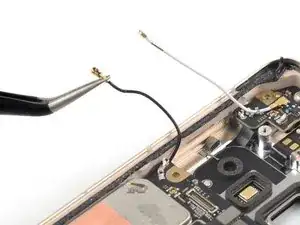
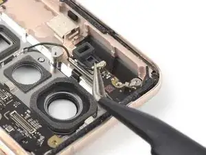
    • Slide a pair of tweezers under the black antenna cable at the left antenna board until they're snug against the metal connector.

    • Lift the coaxial connector straight up to disconnect the black antenna cable.

    • Use your tweezers to carefully loosen the cable from the retaining clips.

  49. AWNwBjYP6ZxirfsB
    AWNwBjYP6ZxirfsB
    VeUNXAhuG6pGQ1y6
    • Use a spudger to disconnect the NFC antenna cable by prying the connector straight up from its socket.

  50. Fp2XXJEEtagIEJ3Q
    Fp2XXJEEtagIEJ3Q
    IXOmsfOvgGUIaZ3U
    • Use a spudger to disconnect the antenna and microphone interconnect cable by prying the connector straight up from its socket.

  51. ESPXHcnwiFm6XyJ6
    ESPXHcnwiFm6XyJ6
    WKqg6I2OAZcpp3EL
    2OkHHXSjJboWvn5O
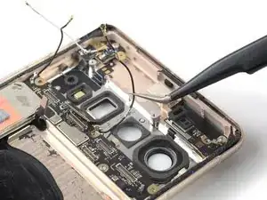
    • Slide a pair of tweezers under the black antenna cable at the right antenna board until they're snug against the metal connector.

    • Lift the coaxial connector straight up to disconnect the black antenna cable.

    • Use your tweezers to carefully loosen the cable from the retaining clips.

  52. XhDG4QJqkFVDuOsm
    XhDG4QJqkFVDuOsm
    iPFm3FMjDUDetltU
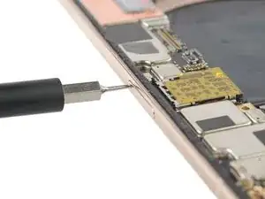
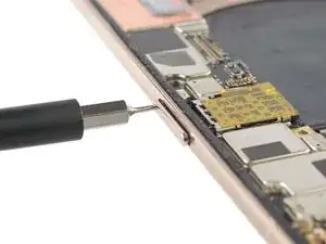
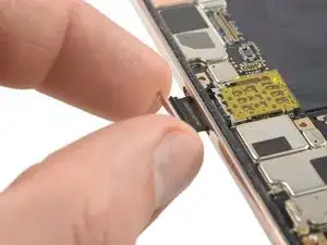
    • Insert a SIM eject tool, bit, or straightened paper clip into the SIM card tray hole.

    • Press the SIM eject tool into the SIM card tray hole to eject the SIM card tray.

  53. jOlDPTDQ6llOmTCK
    jOlDPTDQ6llOmTCK
    PKgk3WFoR13rKpQM
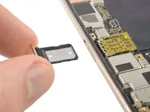
    • Remove the SIM card tray.

  54. 253g2QPsE4PZ6Y4g
    253g2QPsE4PZ6Y4g
    hxROpHUOFmbgndXh
    • Use a Torx T3 screwdriver to remove the four 3.1 mm-long screws securing the motherboard.

  55. QAJcxWUPYLYqRkaP
    QAJcxWUPYLYqRkaP
    5XIQvVwNLOTSLsOs
    • Make sure the motherboard isn't blocked or tangled by any cables during this step.

    • Insert a spudger underneath the top edge of the motherboard.

    • Pry upwards to loosen the motherboard until you can grab it with your fingers.

  56. h5VOWyTXimwAGfMX
    h5VOWyTXimwAGfMX
    1Tp6ZRoD6hTm5rOe
    XdMGk2oFPHegTJIy
    • Grab the top end of the motherboard with your fingers.

    • Pull the motherboard in direction of the top edge of the frame to free the charging port from its recess.

    • Remove the motherboard.

    • Compare your new replacement part to the original part—you may need to transfer components like the antenna cables to your new motherboard.

  57. X3gIIds42S3yO1pu
    X3gIIds42S3yO1pu
    xumQY66gNLa64pMQ
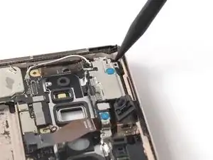
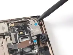
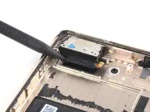
    • Insert the pointed end of a spudger underneath the top right edge of the loudspeaker.

    • Pry upwards to loosen the loudspeaker.

  58. UOdpCg3WtZyLCbDc
    UOdpCg3WtZyLCbDc
    YJqLupBLUX2hGEyp
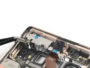
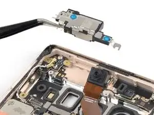
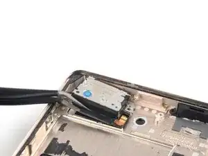
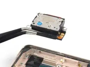
    • Use a pair of tweezers to remove the loudspeaker.

Conclusion

Compare your new replacement part to the original part—you may need to transfer remaining components or remove adhesive backings from the new part before you install it.

To reassemble your device, follow these instructions in reverse order.

To run a diagnostics test with the built-in Pixel Diagnostic tool, click here.

Take your e-waste to an R2 or e-Stewards certified recycler.

Repair didn’t go as planned? Try some basic troubleshooting, or ask our Google Pixel 7 Pro answers community for help.
Dominik Schnabelrauch

Member since: 23/11/16

201162 Reputation

0 comments