Williams tube
The Williams tube, or the Williams–Kilburn tube after inventors Freddie Williams and Tom Kilburn, is an early form of computer memory.[1][2] It was the first random-access digital storage device, and was used successfully in several early computers.[3]
| Computer memory types |
|---|
| Volatile |
| RAM |
| Historical |
|
| Non-volatile |
| ROM |
| NVRAM |
| Early stage NVRAM |
| Magnetic |
| Optical |
| In development |
| Historical |
|
The Williams tube works by displaying a grid of dots on a cathode ray tube (CRT). Due to the way CRTs work, this creates a small charge of static electricity over each dot. The charge at the location of each of the dots is read by a thin metal sheet just in front of the display. Since the display faded over time, it was periodically refreshed. It cycles faster than earlier acoustic delay line memory, at the speed of the electrons inside the vacuum tube, rather than at the speed of sound. However, the system was adversely affected by any nearby electrical fields, and required constant alignment to keep operational. Williams–Kilburn tubes were used primarily on high-speed computer designs.
Williams and Kilburn applied for British patents on 11 December 1946,[4] and 2 October 1947,[5] followed by United States patent applications on 10 December 1947,[6] and 16 May 1949.[7]
Working principle
The Williams tube depends on an effect called secondary emission that occurs on cathode ray tubes (CRTs). When the electron beam strikes the phosphor that forms the display surface, it normally causes it to light up; however, if the beam energy is above a given threshold (depending on the phosphor mix) it also causes electrons to be struck out of the phosphor. These electrons travel a short distance before being attracted back to the CRT surface and falling on it a short distance away. The overall effect is to cause a slight positive charge in the immediate region of the beam where there is a deficit of electrons, and a slight negative charge around the dot where those electrons land. The resulting charge well remains on the surface of the tube for a fraction of a second while the electrons flow back to their original locations.[1] The lifetime depends on the electrical resistance of the phosphor and the size of the well.
The process of creating the charge well is used as the write operation in a computer memory, storing a single binary digit, or bit. A collection of dots or spaces, often one horizontal row on the display, represents a computer word. There is a relationship between the size and spacing of the dots and their lifetime, as well as the ability to reject crosstalk with adjacent dots. This places an upper limit on the memory density, and each Williams tube could typically store about 1024 to 2560 bits of data. Because the electron beam is essentially inertia-free and can be moved anywhere on the display, the computer can access any location, making it a random access memory. Typically, the computer would load the address as an X and Y pair into the driver circuitry and then trigger a time base generator that would sweep the selected locations, reading from or writing to the internal registers, normally implemented as flip-flops.
Reading the memory took place via a secondary effect caused by the writing operation. During the short period when the write takes place, the redistribution of charges in the phosphor creates an electrical current that induces voltage in any nearby conductors. This is read by placing a thin metal sheet just in front of the display side of the CRT. During a read operation, the beam writes to the selected bit locations on the display. Those locations that were previously written to are already depleted of electrons, so no current flows, and no voltage appears on the plate. This allows the computer to determine there was a "1" in that location. If the location had not been written to previously, the write process will create a well and a pulse will be read on the plate, indicating a "0".[1]
Reading a memory location creates a charge well whether or not one was previously there, destroying the original contents of that location, and so any read has to be followed by a write to reinstate the original data. In some systems this was accomplished using a second electron gun inside the CRT that could write to one location while the other was reading the next. Since the display would fade over time, the entire display had to be periodically refreshed using the same basic method. However, as the data is read and then immediately written, this operation can be carried out by external circuitry while the central processing unit (CPU) was busy carrying out other operations. This refresh operation is similar to the memory refresh cycles of DRAM in modern systems.
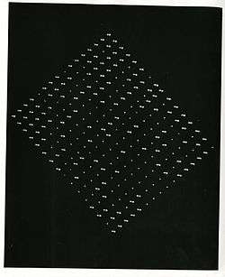
Since the refresh process caused the same pattern to continually reappear on the display, there was a need to be able to erase previously written values. This was normally accomplished by writing to the display just beside the original location. The electrons released by this new write would fall into the previously written well, filling it back in. The original systems produced this effect by writing a small dash, which was easy to accomplish without changing the master timers and simply producing the write current for a slightly longer period. The resulting pattern was a series of dots and dashes. There was a considerable amount of research on more effective erasing systems, with some systems using out-of-focus beams or complex patterns.
Some Williams tubes were made from radar-type cathode ray tubes with a phosphor coating that made the data visible, while other tubes were purpose-built without such a coating. The presence or absence of this coating had no effect on the operation of the tube, and was of no importance to the operators, since the face of the tube was covered by the pickup plate. If a visible output was needed, a second tube connected in parallel with the storage tube, with a phosphor coating, but without a pickup plate, was used as a display device.
Development
Developed at the University of Manchester in England, it provided the medium on which the first electronically stored-memory program was implemented in the Manchester Baby computer, which first successfully ran a program on 21 June 1948.[8] In fact, rather than the Williams tube memory being designed for the Baby, the Baby was a testbed to demonstrate the reliability of the memory.[9][10] Tom Kilburn wrote a 17-line program to calculate the highest proper factor of 218. Tradition at the university has it that this was the only program Kilburn ever wrote.[11]
Williams tubes tended to become unreliable with age, and most working installations had to be "tuned" by hand. By contrast, mercury delay line memory was slower and not truly random access, as the bits were presented serially, which complicated programming. Delay lines also needed hand tuning, but did not age as badly and enjoyed some success in early digital electronic computing despite their data rate, weight, cost, thermal and toxicity problems. However, the Manchester Mark 1, which used Williams tubes, was successfully commercialised as the Ferranti Mark 1. Some early computers in the United States also used Williams tubes, including the IAS machine (originally designed for Selectron tube memory), the UNIVAC 1103, IBM 701, IBM 702 and the Standards Western Automatic Computer (SWAC). Williams tubes were also used in the Soviet Strela-1 and in the Japan TAC (Tokyo Automatic Computer).[12]
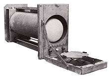 A Williams–Kilburn tube
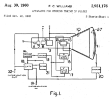 Diagram of Williams tube memory from the 1947 patent
- SWAC Williams tube assembly
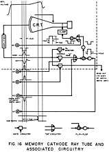 Diagram of SWAC Williams tube module
See also
- Atanasoff–Berry computer – Used a type of memory called regenerative capacitor memory
- Mellon optical memory
References
Notes
- Kilburn, Tom (1990), "From Cathode Ray Tube to Ferranti Mark I", Resurrection, The Computer Conservation Society, 1 (2), ISSN 0958-7403, retrieved 15 March 2012
- Brian Napper (25 November 1998). "Williams Tube". University of Manchester. Retrieved 1 October 2016.
- "Early computers at Manchester University", Resurrection, The Computer Conservation Society, 1 (4), Summer 1992, ISSN 0958-7403, retrieved 7 July 2010
- GB Patent 645,691
- GB Patent 657,591
- U.S. Patent 2,951,176
- U.S. Patent 2,777,971
- Napper, Brian, Computer 50: The University of Manchester Celebrates the Birth of the Modern Computer, archived from the original on 4 May 2012, retrieved 26 May 2012
- Williams, F.C.; Kilburn, T. (Sep 1948), "Electronic Digital Computers", Nature, 162 (4117): 487, doi:10.1038/162487a0. Reprinted in The Origins of Digital Computers
- Williams, F.C.; Kilburn, T.; Tootill, G.C. (Feb 1951), "Universal High-Speed Digital Computers: A Small-Scale Experimental Machine", Proc. IEE, 98 (61): 13–28, doi:10.1049/pi-2.1951.0004.
- Lavington 1998, p. 11
- Research, United States Office of Naval (1953). A survey of automatic digital computers. Office of Naval Research, Dept. of the Navy. p. 87.
Bibliography
- Lavington, Simon (1998), A History of Manchester Computers (2nd ed.), The British Computer Society, ISBN 978-1-902505-01-5
Further reading
- Bashe, Charles J. (1986). IBM's Early Computers. MIT Press. ISBN 0-262-02225-7.
- Lavington, Simon H. (1980). Early British Computers. Manchester University Press. ISBN 0-932376-08-8.
- Randell, Brian (1982). The Origins of Digital Computers (3rd ed.). Springer-Verlag. ISBN 0-387-11319-3.
External links
| Wikimedia Commons has media related to Williams tubes. |