Cathode
A cathode is the electrode from which a conventional current leaves a polarized electrical device. This definition can be recalled by using the mnemonic CCD for Cathode Current Departs. A conventional current describes the direction in which positive charges move. Electrons have a negative electrical charge, so the movement of electrons is opposite to that of the conventional current flow. Consequently, the mnemonic cathode current departs also means that electrons flow into the device's cathode from the external circuit.
The electrode through which conventional current flows the other way, into the device, is termed an anode.
Charge flow
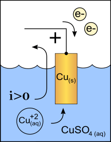
Conventional current flow is from cathode to anode outside of the cell or device (with electrons moving in the opposite direction), regardless of the cell or device type and operating mode.
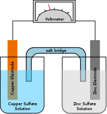
Cathode polarity with respect to the anode can be positive or negative depending on how the device is being operated. Positively charged cations always move towards the cathode and negatively charged anions move towards the anode, although cathode polarity depends on the device type, and can even vary according to the operating mode. In a device which absorbs energy of charge (such as recharging a battery), the cathode is negative (electrons flow into the cathode, and charge flows out of it), and in a device which provides energy (such as battery in use), the cathode is positive (electrons flow into it and charge flows out): A battery or galvanic cell in use has a cathode that is the positive terminal since that is where the current flows out of the device. This outward current is carried internally by positive ions moving from the electrolyte to the positive cathode (chemical energy is responsible for this "uphill" motion). It is continued externally by electrons moving into the battery which constitutes positive current flowing outwards. For example, the Daniell galvanic cell's copper electrode is the positive terminal and the cathode. A battery that is recharging or an electrolytic cell performing electrolysis has its cathode as the negative terminal, from which current exits the device and returns to the external generator as charge enters the battery/ cell. For example, reversing the current direction in a Daniell galvanic cell converts it into an electrolytic cell[1] where the copper electrode is the positive terminal and also the anode. In a diode, the cathode is the negative terminal at the pointed end of the arrow symbol, where current flows out of the device. Note: electrode naming for diodes is always based on the direction of the forward current (that of the arrow, in which the current flows "most easily"), even for types such as Zener diodes or solar cells where the current of interest is the reverse current. In vacuum tubes (including cathode ray tubes) it is the negative terminal where electrons enter the device from the external circuit and proceed into the tube's near-vacuum, constituting a positive current flowing out of the device.
Etymology
The word was coined in 1834 from the Greek κάθοδος (kathodos), 'descent' or 'way down', by William Whewell, who had been consulted[2] by Michael Faraday over some new names needed to complete a paper on the recently discovered process of electrolysis. In that paper Faraday explained that when an electrolytic cell is oriented so that electric current traverses the "decomposing body" (electrolyte) in a direction "from East to West, or, which will strengthen this help to the memory, that in which the sun appears to move", the cathode is where the current leaves the electrolyte, on the West side: "kata downwards, `odos a way ; the way which the sun sets".[3]
The use of 'West' to mean the 'out' direction (actually 'out' → 'West' → 'sunset' → 'down', i.e. 'out of view') may appear unnecessarily contrived. Previously, as related in the first reference cited above, Faraday had used the more straightforward term "exode" (the doorway where the current exits). His motivation for changing it to something meaning 'the West electrode' (other candidates had been "westode", "occiode" and "dysiode") was to make it immune to a possible later change in the direction convention for current, whose exact nature was not known at the time. The reference he used to this effect was the Earth's magnetic field direction, which at that time was believed to be invariant. He fundamentally defined his arbitrary orientation for the cell as being that in which the internal current would run parallel to and in the same direction as a hypothetical magnetizing current loop around the local line of latitude which would induce a magnetic dipole field oriented like the Earth's. This made the internal current East to West as previously mentioned, but in the event of a later convention change it would have become West to East, so that the West electrode would not have been the 'way out' any more. Therefore, "exode" would have become inappropriate, whereas "cathode" meaning 'West electrode' would have remained correct with respect to the unchanged direction of the actual phenomenon underlying the current, then unknown but, he thought, unambiguously defined by the magnetic reference. In retrospect the name change was unfortunate, not only because the Greek roots alone do not reveal the cathode's function any more, but more importantly because, as we now know, the Earth's magnetic field direction on which the "cathode" term is based is subject to reversals whereas the current direction convention on which the "exode" term was based has no reason to change in the future.
Since the later discovery of the electron, an easier to remember, and more durably technically correct (although historically false), etymology has been suggested: cathode, from the Greek kathodos, 'way down', 'the way (down) into the cell (or other device) for electrons'.
In chemistry
In chemistry, a cathode is the electrode of an electrochemical cell at which reduction occurs; a useful mnemonic to remember this is AnOx RedCat (Oxidation at the Anode = Reduction at the Cathode). Another mnemonic is to note the cathode has a 'c', as does 'reduction'. Hence, reduction at the cathode. Perhaps most useful would be to remember cathode corresponds to cation (acceptor) and anode corresponds to anion (donor). The cathode can be negative like when the cell is electrolytic (where electrical energy provided to the cell is being used for decomposing chemical compounds); or positive as when the cell is galvanic (where chemical reactions are used for generating electrical energy). The cathode supplies electrons to the positively charged cations which flow to it from the electrolyte (even if the cell is galvanic, i.e., when the cathode is positive and therefore would be expected to repel the positively charged cations; this is due to electrode potential relative to the electrolyte solution being different for the anode and cathode metal/electrolyte systems in a galvanic cell).
The cathodic current, in electrochemistry, is the flow of electrons from the cathode interface to a species in solution. The anodic current is the flow of electrons into the anode from a species in solution.
Electrolytic cell
In an electrolytic cell, the cathode is where the negative polarity is applied to drive the cell. Common results of reduction at the cathode are hydrogen gas or pure metal from metal ions. When discussing the relative reducing power of two redox agents, the couple for generating the more reducing species is said to be more "cathodic" with respect to the more easily reduced reagent.
Galvanic cell
In a galvanic cell, the cathode is where the positive pole is connected to allow the circuit to be completed: as the anode of the galvanic cell gives off electrons, they return from the circuit into the cell through the cathode.
Electroplating metal cathode (electrolysis)
When metal ions are reduced from ionic solution, they form a pure metal surface on the cathode. Items to be plated with pure metal are attached to and become part of the cathode in the electrolytic solution.
In electronics
Vacuum tubes
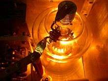
In a vacuum tube or electronic vacuum system, the cathode is a metal surface which emits free electrons into the evacuated space. Since the electrons are attracted to the positive nuclei of the metal atoms, they normally stay inside the metal and require energy to leave it; this is called the work function of the metal.[4] Cathodes are induced to emit electrons by several mechanisms:[4]
- Thermionic emission: The cathode can be heated. The increased thermal motion of the metal atoms "knocks" electrons out of the surface, an effect called thermionic emission. This technique is used in most vacuum tubes.
- Field electron emission: A strong electric field can be applied to the surface by placing an electrode with a high positive voltage near the cathode. The positively charged electrode attracts the electrons, causing some electrons to leave the cathode's surface.[4] This process is used in cold cathodes in some electron microscopes,[5][6][7] and in microelectronics fabrication,[6]
- Secondary emission: An electron, atom or molecule colliding with the surface of the cathode with enough energy can knock electrons out of the surface. These electrons are called secondary electrons. This mechanism is used in gas-discharge lamps such as neon lamps.
- Photoelectric emission: Electrons can also be emitted from the electrodes of certain metals when light of frequency greater than the threshold frequency falls on it. This effect is called photoelectric emission, and the electrons produced are called photoelectrons.[4] This effect is used in phototubes and image intensifier tubes.
Cathodes can be divided into two types:
Hot cathode
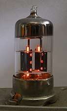
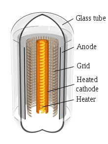

A hot cathode is a cathode that is heated by a filament to produce electrons by thermionic emission.[4][8] The filament is a thin wire of a refractory metal like tungsten heated red-hot by an electric current passing through it. Before the advent of transistors in the 1960s, virtually all electronic equipment used hot-cathode vacuum tubes. Today hot cathodes are used in vacuum tubes in radio transmitters and microwave ovens, to produce the electron beams in older cathode ray tube (CRT) type televisions and computer monitors, in x-ray generators, electron microscopes, and fluorescent tubes.
There are two types of hot cathodes:[4]
- Directly heated cathode: In this type, the filament itself is the cathode and emits the electrons directly. Directly heated cathodes were used in the first vacuum tubes, but today they are only used in fluorescent tubes, some large transmitting vacuum tubes, and all X-ray tubes.
- Indirectly heated cathode: In this type, the filament is not the cathode but rather heats the cathode which then emits electrons. Indirectly heated cathodes are used in most devices today. For example, in most vacuum tubes the cathode is a nickel tube with the filament inside it, and the heat from the filament causes the outside surface of the tube to emit electrons.[8] The filament of an indirectly heated cathode is usually called the heater. The main reason for using an indirectly heated cathode is to isolate the rest of the vacuum tube from the electric potential across the filament. Many vacuum tubes use alternating current to heat the filament. In a tube in which the filament itself was the cathode, the alternating electric field from the filament surface would affect the movement of the electrons and introduce hum into the tube output. It also allows the filaments in all the tubes in an electronic device to be tied together and supplied from the same current source, even though the cathodes they heat may be at different potentials.
In order to improve electron emission, cathodes are treated with chemicals, usually compounds of metals with a low work function. Treated cathodes require less surface area, lower temperatures and less power to supply the same cathode current. The untreated tungsten filaments used in early tubes (called "bright emitters") had to be heated to 1400 °C (~2500 °F), white-hot, to produce sufficient thermionic emission for use, while modern coated cathodes produce far more electrons at a given temperature so they only have to be heated to 425–600 °C (~800–1100 °F) ()[4][9][10] There are two main types of treated cathodes:[4][8]
- Coated cathode – In these the cathode is covered with a coating of alkali metal oxides, often barium and strontium oxide. These are used in low-power tubes.
- Thoriated tungsten – In high-power tubes, ion bombardment can destroy the coating on a coated cathode. In these tubes a directly heated cathode consisting of a filament made of tungsten incorporating a small amount of thorium is used. The layer of thorium on the surface which reduces the work function of the cathode is continually replenished as it is lost by diffusion of thorium from the interior of the metal.[11]
Cold cathode
This is a cathode that is not heated by a filament. They may emit electrons by field electron emission, and in gas-filled tubes by secondary emission. Some examples are electrodes in neon lights, cold-cathode fluorescent lamps (CCFLs) used as backlights in laptops, thyratron tubes, and Crookes tubes. They do not necessarily operate at room temperature; in some devices the cathode is heated by the electron current flowing through it to a temperature at which thermionic emission occurs. For example, in some fluorescent tubes a momentary high voltage is applied to the electrodes to start the current through the tube; after starting the electrodes are heated enough by the current to keep emitting electrons to sustain the discharge.
Cold cathodes may also emit electrons by photoelectric emission. These are often called photocathodes and are used in phototubes used in scientific instruments and image intensifier tubes used in night vision goggles.
Diodes

In a semiconductor diode, the cathode is the N–doped layer of the PN junction with a high density of free electrons due to doping, and an equal density of fixed positive charges, which are the dopants that have been thermally ionized. In the anode, the converse applies: It features a high density of free "holes" and consequently fixed negative dopants which have captured an electron (hence the origin of the holes).
When P and N-doped layers are created adjacent to each other, diffusion ensures that electrons flow from high to low density areas: That is, from the N to the P side. They leave behind the fixed positively charged dopants near the junction. Similarly, holes diffuse from P to N leaving behind fixed negative ionised dopants near the junction. These layers of fixed positive and negative charges are collectively known as the depletion layer because they are depleted of free electrons and holes. The depletion layer at the junction is at the origin of the diode's rectifying properties. This is due to the resulting internal field and corresponding potential barrier which inhibit current flow in reverse applied bias which increases the internal depletion layer field. Conversely, they allow it in forwards applied bias where the applied bias reduces the built in potential barrier.
Electrons which diffuse from the cathode into the P-doped layer, or anode, become what are termed "minority carriers" and tend to recombine there with the majority carriers, which are holes, on a timescale characteristic of the material which is the p-type minority carrier lifetime. Similarly, holes diffusing into the N-doped layer become minority carriers and tend to recombine with electrons. In equilibrium, with no applied bias, thermally assisted diffusion of electrons and holes in opposite directions across the depletion layer ensure a zero net current with electrons flowing from cathode to anode and recombining, and holes flowing from anode to cathode across the junction or depletion layer and recombining.
Like a typical diode, there is a fixed anode and cathode in a Zener diode, but it will conduct current in the reverse direction (electrons flow from anode to cathode) if its breakdown voltage or "Zener voltage" is exceeded.
See also
References
- Archived 4 June 2011 at the Wayback Machine, Daniell cell can be reversed to, technically, produce an electrolytic cell.
- Ross, S (1 November 1961). "Faraday consults the scholars: the origins of the terms of electrochemistry". Notes and Records of the Royal Society of London. 16 (2): 187–220. doi:10.1098/rsnr.1961.0038.
- Faraday, Michael (1849). Experimental Researches In Electricity. 1. London: The University of London.
- Avadhanulu, M.N.; P.G. Kshirsagar (1992). A Textbook Of Engineering Physics For B.E., B.Sc. S. Chand. pp. 345–348. ISBN 978-8121908177. Archived from the original on 2 January 2014.
- "Field emission". Encyclopædia Britannica online. Encyclopædia Britannica, Inc. 2014. Archived from the original on 2 December 2013. Retrieved 15 March 2014.
- Poole, Charles P. Jr. (2004). Encyclopedic Dictionary of Condensed Matter Physics, Vol. 1. Academic Press. p. 468. ISBN 978-0080545233. Archived from the original on 24 December 2017.
- Flesch, Peter G. (2007). Light and Light Sources: High-Intensity Discharge Lamps. Springer. pp. 102–103. ISBN 978-3540326854. Archived from the original on 24 December 2017.
- Ferris, Clifford "Electron tube fundamentals" in Whitaker, Jerry C. (2013). The Electronics Handbook, 2nd Ed. CRC Press. pp. 354–356. ISBN 978-1420036664. Archived from the original on 2 January 2014.
- Poole, Ian (2012). "Vacuum tube electrodes". Vacuum Tube Theory Basics Tutorial. Radio-Electronics.com, Adrio Communications. Archived from the original on 4 November 2013. Retrieved 3 October 2013.
- Jones, Martin Hartley (1995). A Practical Introduction to Electronic Circuits. UK: Cambridge Univ. Press. p. 49. ISBN 978-0521478793. Archived from the original on 2 January 2014.
- Sisodia, M. L. (2006). Microwave Active Devices Vacuum and Solid State. New Age International. p. 2.5. ISBN 978-8122414479. Archived from the original on 2 January 2014.
