Introduction
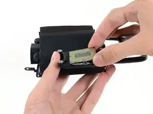
Replace or upgrade the CPU in your Late 2012 27" iMac. Don't forget to apply a new layer of thermal compound before reassembling your iMac.
Follow our thermal paste guide for instructions on cleaning and preparing the thermal surfaces and applying a new layer of thermal compound onto the CPU and GPU dies.
Before beginning any work on your iMac: Unplug the computer and press and hold the power button for ten seconds to discharge the power supply's capacitors.
Be very careful not to touch the capacitor leads or any exposed solder joints on the back of the power supply. Only handle the board by the edges.
Tools
Parts
-
-
With the hinge free to move, the iMac will be unbalanced and hard to work on. Repairs can be completed with the iMac laying down, but are faster and easier with an iMac service wedge.
-
If you are using the iFixit cardboard service wedge, follow these assembly directions to put it together.
-
-
-
Starting on the left of the display, near the power button, insert the iMac Opening Tool into the gap between the glass panel and the rear case.
-
-
-
Use the tool like a pizza cutter—roll it along through the gap, and it will cut the foam adhesive through the center.
-
Run the tool up along the left side of the display.
-
-
-
Set the iMac face-up on a table.
-
Starting from the top right corner of the iMac, insert a plastic card between the display and frame.
-
-
-
Gently twist the plastic card to open the space between the display and frame, and cut any remaining adhesive near the corner.
-
-
-
Put the card into the corner again and let it stay there to keep the adhesive from resettling.
-
-
-
With the cards inserted as shown near the corners, gently twist the cards to increase the gap between display and case.
-
If there are any sections that seem to stick and won't separate, stop twisting and use one of the cards to cut the adhesive in the problem area.
-
Begin to lift the top of the display up from the frame.
-
-
-
While holding the display up with one hand, use the other to unplug the display power cable.
-
-
-
Flip up the metal retaining bracket on the display data cable.
-
Disconnect the display data cable.
-
-
-
Lift the display up to a near-vertical position.
-
Remove as much of the adhesive as possible by grabbing it at the outer edges, and then pulling or rolling it towards the middle.
-
-
-
If necessary, a plastic card can be used to cut any remaining sections of the bottom adhesive strip.
-
-
-
Lift the display up from the frame and remove it from the iMac. Lay the display face down on a flat, soft surface.
-
It may be necessary to slowly lift from one side, to peel against the remaining adhesive.
-
-
-
If there is a wire or cable underneath adhesive tape, always pull the tape off first.
-
If the cable is glued to the chassis, use a heated iOpener or a hair dryer to soften the adhesive first. You can then slide an opening pick underneath the cable to loosen it. Never pull directly on the delicate connectors.
-
Slide an opening pick underneath the foam cushion pieces to separate them from the display, and gently pull them off. You may need some double sided tape to re-attach them to the new display.
-
-
-
Unplug the left speaker cable by pulling it straight up out of its socket on the logic board.
-
De-route the cable from the gap between the hard drive and logic board.
-
-
-
Lift the left speaker straight up, until the power button cable is exposed (about 0.5 inches).
-
-
-
Lift the left speaker straight up and remove it from the iMac.
-
Push from the connector end as you pull from the speaker end to thread the cable under the hard drive's right bracket.
-
-
-
Grab the hard drive and left hard drive bracket together.
-
Tilt the left side up away from the rear case, and slide the assembly to the left.
-
Remove the hard drive and left hard drive bracket from the iMac.
-
-
-
Remove the following four screws securing the power supply to the rear case (size T8 or T10 depending on the exact model):
-
Two 23.7 mm Torx screws
-
Two 7.3 mm Torx screws
-
-
-
Move the power supply board towards the left edge of the case and up to free it from the notch in the logic board.
-
-
-
Depress the tab on the DC power cable connector, then pull it straight out of its socket on the back of the logic board.
-
-
-
Flip the top of the power supply towards you, like opening a mailbox, to reveal the AC inlet cable connector.
-
Disconnect the AC inlet cable connector.
-
-
-
Gently rock the right speaker slightly to the right, to allow access to its cable's connection on the logic board.
-
-
-
Use a spudger to loosen the right speaker cable's connector from its socket on the logic board.
-
Pull the connector to the right to remove it from its socket.
-
-
-
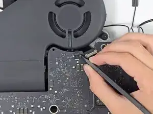
Use the tip of a spudger to disconnect the fan cable's connector from its socket on the logic board.
-
-
-
Peel the black tape connecting the fan to the exhaust duct back slightly.
-
Leave the tape in place on the exhaust duct—you only need to expose the joint to free the fan.
-
-
-
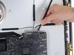
Use the flat end of a spudger to disconnect each of the four antenna connectors from the AirPort/Bluetooth card.
-
Leftmost
-
Top
-
Upper right
-
Lower right
-
-
-
Flip up the metal retaining bracket on the iSight camera cable.
-
Pull the camera cable connector straight out of its socket, toward the top of the iMac.
-
-
-
Use the flat end of a spudger to disconnect the headphone jack cable connector from its socket on the logic board.
-
Gently push the cable out of the way.
-
-
-
Remove the following screws from the front of the logic board:
-
Two 23.7 mm T10 screws
-
Four 7.4 mm T10 screws
-
One 20.8 mm T25 spacer screw
-
One captive T10 screw
-
-
-
Pull the cable and connector through the right hard drive bracket. Move the cable to the right side of the iMac, out of the way of the exhaust port.
-
-
-
Tilt the logic board slightly forward.
-
Lift the logic board straight up and out of the iMac. Be careful not to snag on any of the screw posts attached to the inside of the rear case.
-
-
-
When reassembling your iMac, be very careful to align the exterior I/O ports correctly. The logic board can sit crooked even when secured with all its screws.
-
You can use a USB flashdrive or ethernet cable to ensure the logic board is seated correctly while you screw it in.
-
-
-
Remove the spring plate from behind the CPU heat sink.
-
Lift and remove the backing plate from behind the CPU heat sink. The backing plate has two posts that fit into alignment holes in the logic board.
-
-
-
Insert the flat end of a spudger between the CPU and heat sink.
-
Gently pry the CPU up by slightly twisting the spudger.
-
Remove the CPU from the heat sink. Be careful not to touch the contacts.
-
-
-
Replace the backing plate on the motherboard, and hold it in place while you turn the board over so the side with the CPU socket faces up.
-
-
-
Before installing the heat sink, see our thermal paste guide for instructions on cleaning and preparing the thermal surfaces and applying a new layer of thermal compound onto the CPU and GPU dies.
-
For the VRAM chips surrounding the GPU, install thermal pads or a thick thermal paste such as K5-PRO, rather than regular thermal paste.
-
The CPU
-
The GPU
-
The VRAM chips
-
The heat sink plates
-
-
-
Align the CPU so that the cutouts in the CPU match the tabs in the socket.
-
Gently place the CPU in the socket. Try to set it straight down and avoid sliding it around once it is in the socket.
-
-
-
Align the holes on the CPU section of the heat sink with the pins on the backing plate.
-
Set the heat sink straight down on the CPU, GPU, and VRAM chips.
-
-
-
Keeping inward pressure on both the heat sink and the backing plate, flip the logic board over so the heat sink faces down.
-
-
-
Place the spring plate on the backing plate.
-
Carefully thread one of the CPU heat sink screws slightly into the heat sink so that just a couple threads are engaged.
-
Press down on the opposite corner of the spring plate from where you just installed a screw.
-
While holding the corner down, thread another screw into that corner of the heat sink, again just tightening it until a couple threads are engaged.
-
-
-
Repeat the process of pressing down the spring plate and slightly threading in the screws to install the remaining two heat sink screws.
-
Tighten the screws down a little at a time in the same order that you installed them—in an "X" pattern starting at one corner and then crossing to the opposite corner.
-
To reassemble your device, follow these instructions in reverse and use our Adhesive Strips Guide to reattach the display glass.
Take your e-waste to an R2 or e-Stewards certified recycler.
Repair didn’t go as planned? Try some basic troubleshooting, or ask our Answers community for help.
12 comments
Is it possible to replace the 3470 i5 i7 3770 without any problem? I've also seen this ttp://www.ebay.es/itm/SATA-Blade-SSD-Module-Dual-SSD-Drive-Kit-for-iMac-27-Inch-2012-Model-/290967355431?pt=US_Drive_Cables_dapters&hash=item43bf018027&_uhb=1 It works to mount drive fusion?
Jesus -
Hi, I wanted to ask to see if someone had replaced the cpu end imac 2012 i5 3470 by i7 3770 ...
Jesus -
i am glad i have found this guide. Thank you so much for this guide. But i wonder if i want to upgrade my cpu with i7, which i7 model should i upgrade? And after reassembly do we need to make any setups on osx?
And finally; how we can re-attache the screen? Do we need some kind of glue or what?
No Name -


This instruction page is not clear and is ambiguous if you have to do all the steps to just change the power supply please clarify another words do I have to remove the speaker and the hard drive to replace the power supply?
crawfordjohn -
This is a display removal guide not the power supply guide!Here’s the guide you need to follow for that iMac Intel 27" EMC 2546 Power Supply Replacement
Dan -