Introduction
This repair guide was authored by the iFixit staff and hasn’t been endorsed by Google. Learn more about our repair guides here.
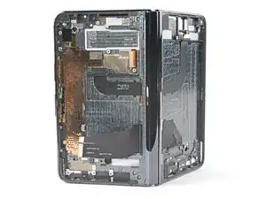
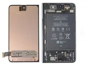
Use this guide to replace the inner screen assembly in your Google Pixel Fold.
The inner screen assembly is composed of the inner screen, fingerprint sensor, and volume button pre-installed in a new frame. This repair requires you to transfer all of the internal components into the assembly.
Note: Some photos in this guide were taken at different states of disassembly. Any visual discrepancies won't affect the guide procedure.
Tools
Parts
-
-
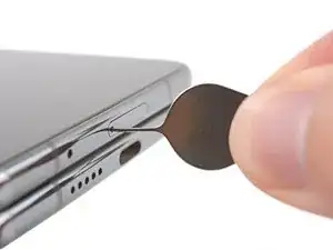
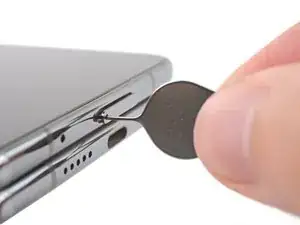
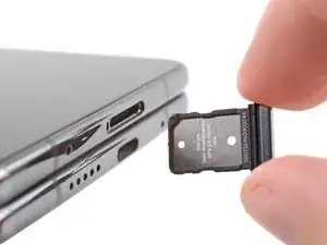
Insert a SIM eject tool, bit, or straightened paper clip into the SIM card tray hole.
-
Press firmly to eject the SIM card tray.
-
-
-
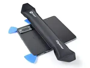
Lay the phone down on a clean, smooth surface so the back glass is facing up.
-
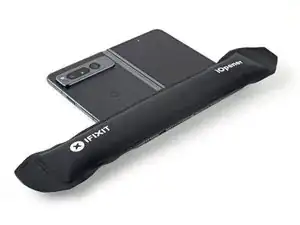
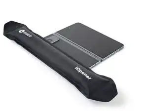
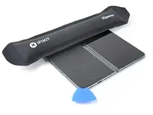
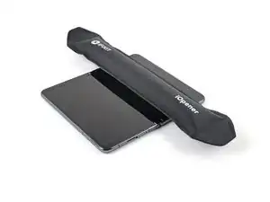
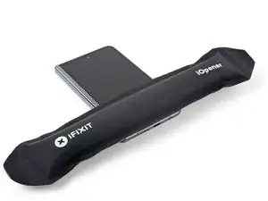
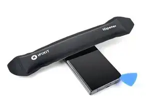
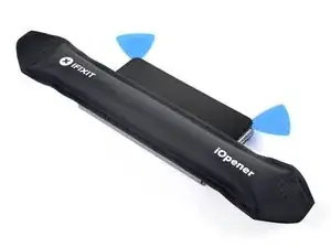
Heat an iOpener and apply it to the bottom edge of the back glass for two minutes.
-
-
-
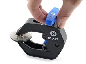
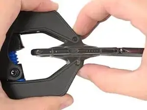
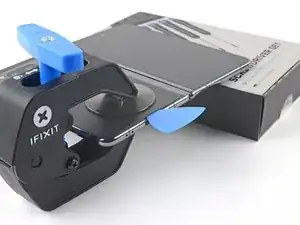
Pull the blue handle backwards to unlock the Anti-Clamp's arms.
-
Unfold your phone completely and slide the Anti-Clamp arms over the left edge of the back glass, below the Google "G" logo.
-
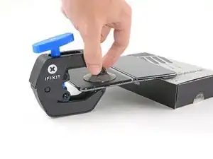
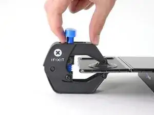
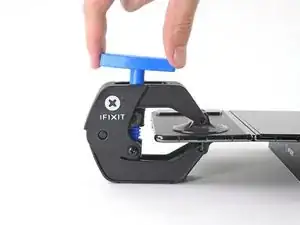
Position the suction cups near the bottom edge of the phone—one on the front, and one on the back.
-
Squeeze the cups together to apply suction to the desired area.
-
-
-
Place an object under your phone, like a box or a stack of books, so it rests level while between the Anti-Clamp's arms.
-
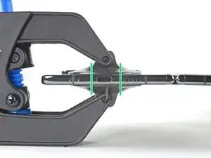
Pull the blue handle forward to lock the arms.
-
Turn the handle clockwise 360 degrees or until the cups start to stretch.
-
Make sure the suction cups remain aligned with each other. If they begin to slip out of alignment, detach the suction cups and realign the arms.
-
-
-
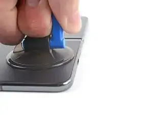
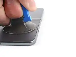
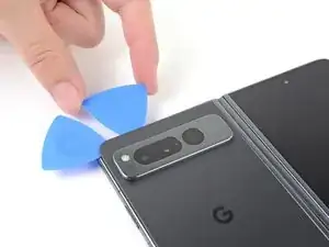
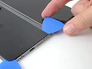
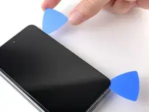
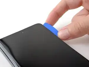
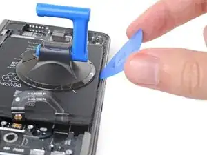
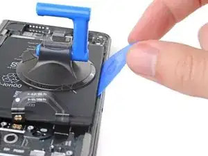
Apply a suction cup to the back glass, as close to the center of the bottom edge as possible.
-
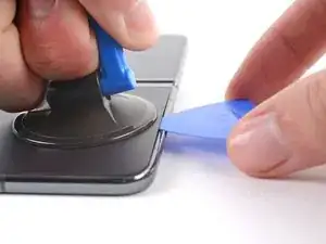
Pull up on the suction cup with strong, steady force to create a gap between the back glass and the frame.
-
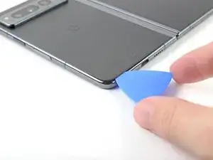
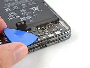
Insert an opening pick into the gap.
-
-
-
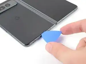
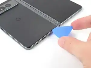
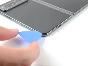
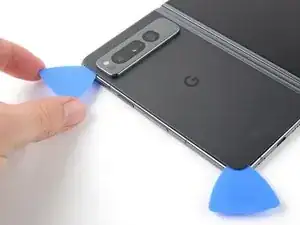
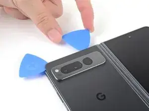
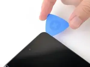
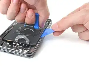
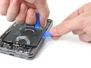
Slide the opening pick back and forth along the bottom edge to separate the adhesive.
-
Leave the opening pick in the bottom left corner before continuing.
-
-
-
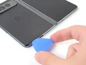
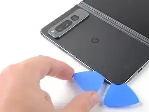
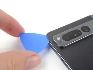
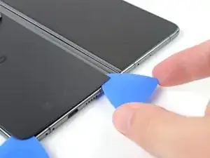
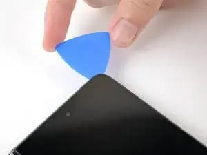
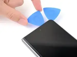
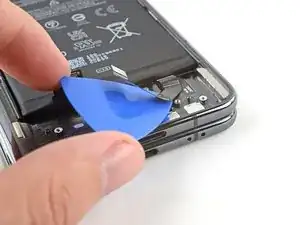
Insert a second opening pick at the bottom left corner.
-
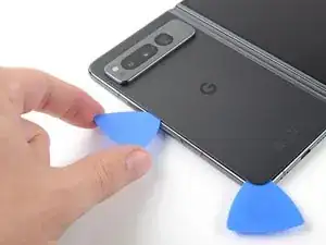
Slide the opening pick toward the top left corner to separate the adhesive.
-
Leave the opening pick in the top left corner before continuing.
-
-
-
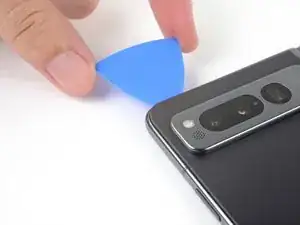
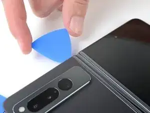
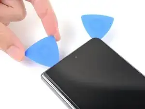
Insert a third opening pick in the top left corner.
-
Slide the opening pick toward the top right corner to separate the adhesive.
-
-
-
Angle your pick so it's as flat as possible to the back glass.
-
Rotate the opening pick around the top right corner to separate the adhesive.
-
-
-
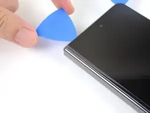
Insert a fourth opening pick in the top right corner.
-
Slide the opening pick toward the bottom right corner to separate the adhesive.
-
-
-
Angle your pick so it's as flat as possible to the back glass.
-
Rotate the opening pick around the bottom right corner to separate the adhesive.
-
-
-
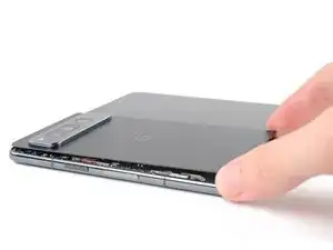
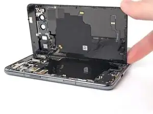
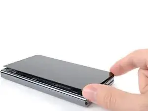
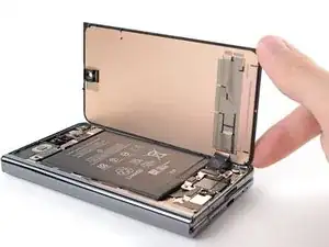
Swing the left edge of the back glass up and over the right edge of the phone.
-
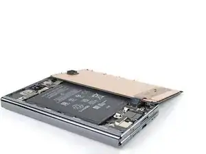
Lay the back glass to the right side of the phone before continuing.
-
-
-
Use a Torx Plus 3IP driver to remove the two 2.8 mm‑long screws securing the middle bracket.
-
-
-
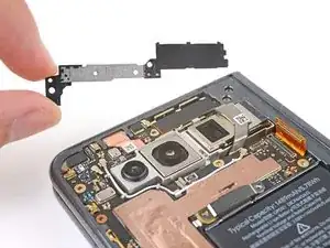
Use tweezers, or your fingers, to pull the middle bracket toward the left edge of the phone and release its clip.
-
Remove the middle bracket.
-
-
-
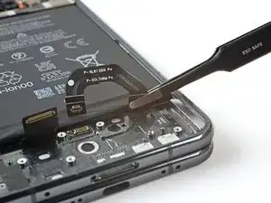
Use the point of a spudger to pry up and disconnect the back glass cable from the motherboard.
-
-
-
If you're reusing your back glass, use tweezers to remove big chunks of adhesive from the perimeter of the back glass.
-
Repeat for any adhesive on the frame.
-
Use isopropyl alcohol (>90%) and a lint-free cloth to remove any remaining adhesive residue.
-
Follow this guide to replace the back glass adhesive with custom cut strips.
-
-
-
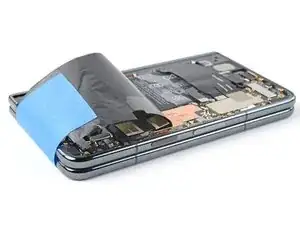
Peel the bottom of the graphite sheet toward the top of the phone until you can access the bottom bracket.
-
Use your hands, or tape with light adhesive, to keep the graphite sheet out of the way.
-
If you completely removed your graphite sheet, follow this guide to replace it.
-
If you don't have custom cut adhesive strips for the antenna, use double-sided tape, like Tesa Tape, to secure the graphite sheet to the logic board.
-
-
-
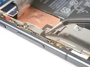
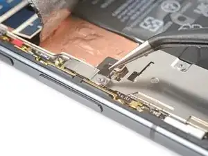
Use tweezers, or a clean fingernail, to pull the black screw cover off the top screw on the bottom bracket.
-
-
-
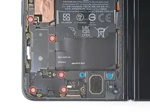
Use a Torx Plus 3IP driver to remove the five 3.1 mm‑long screws securing the bottom bracket.
-
-
-
Use tweezers, or your fingers, to pull the bottom bracket toward the bottom edge of the phone and release its clip.
-
Remove the bottom bracket.
-
-
-
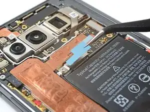
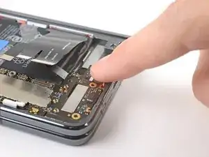
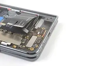
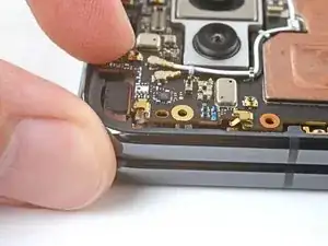
Use a point of a spudger to pry up and disconnect the flip battery and bottom interconnect press connectors.
-
-
-
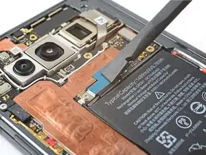
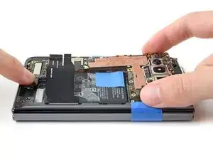
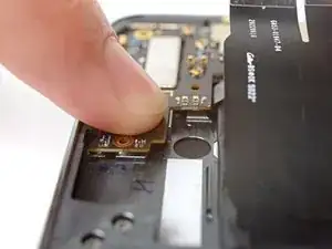
Peel off the new conductive tape from its liner and apply the sticky side to the bottom interconnect connector, making sure to bridge the logic board.
-
-
-
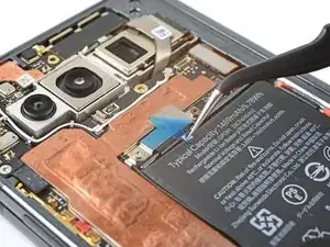
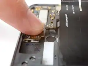
Use a spudger, or your fingers, to press down the conductive tape and adhere it.
-
Use tweezers, or your fingers, to pull on the tab and expose the tape.
-
-
-
If your graphite sheet is taped out of the way, remove the tape now.
-
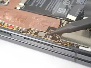
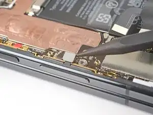
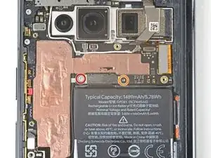
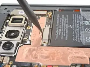
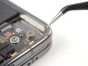
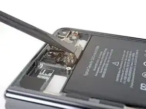
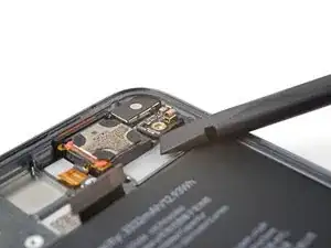
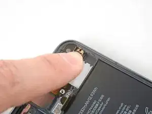
Use the point of a spudger to pry up and disconnect the ultra wideband antenna press connector.
-
-
-
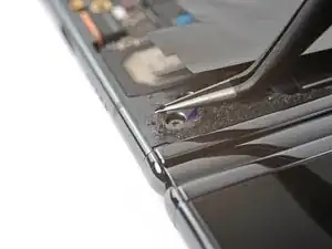
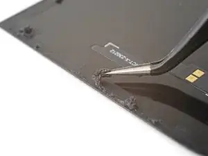
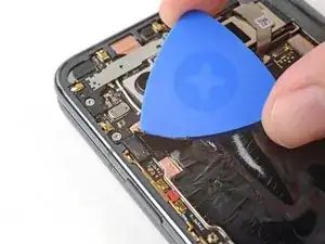
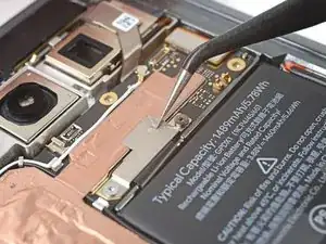
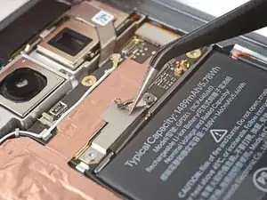
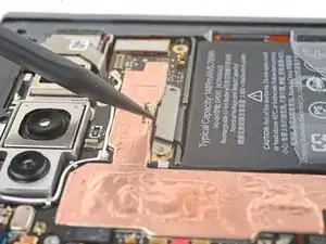
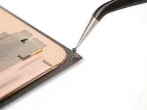
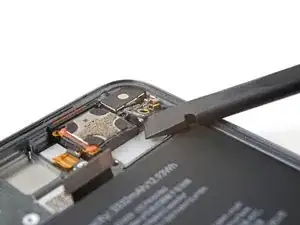
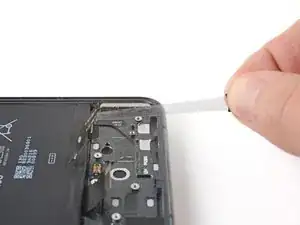
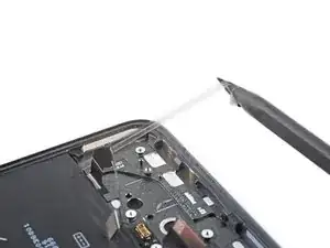
Slide an opening pick under the top of the graphite sheet to separate the thermal insulator adhesive.
-
-
-
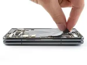
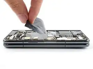
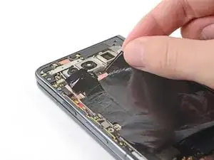
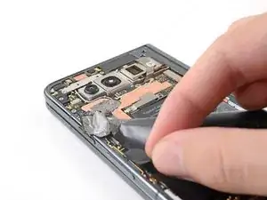
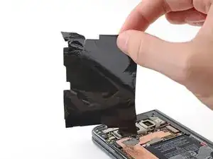
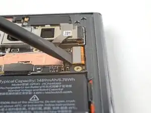
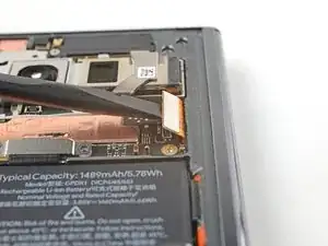
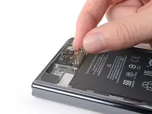
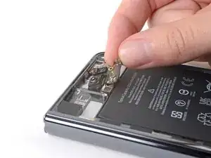
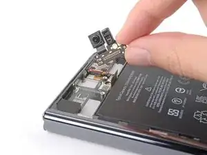
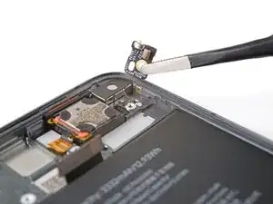
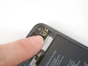
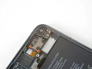
Peel the graphite sheet off the logic board to separate the remaining adhesive.
-
Remove the graphite sheet.
-
-
-
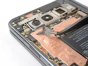
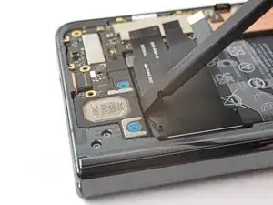
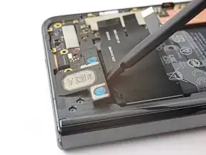
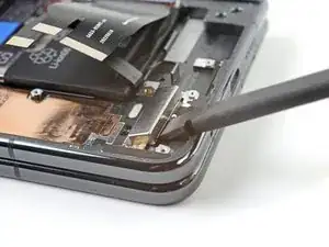
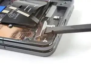
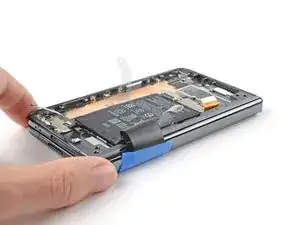
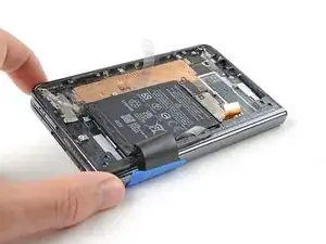
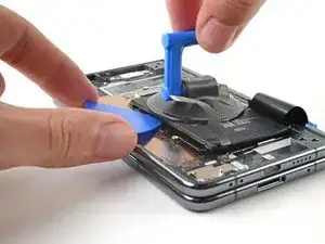
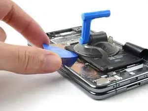
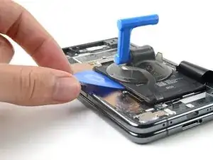
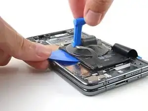
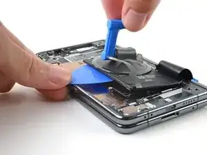
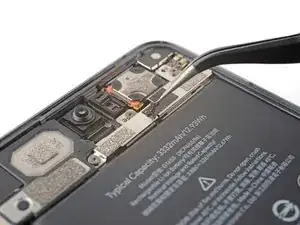
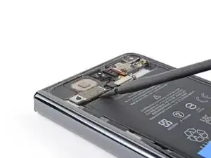
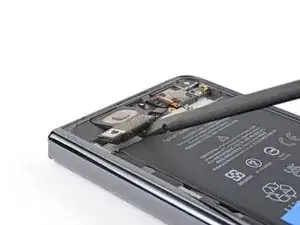
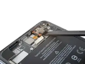
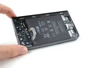
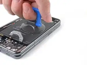
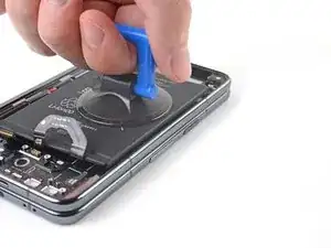
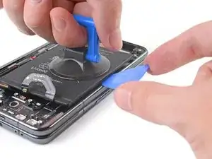
Insert the flat end of a spudger between the battery and the bottom speaker.
-
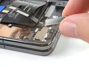
Twist the spudger to separate the adhesive securing the bottom speaker.
-
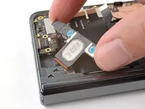
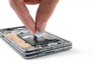
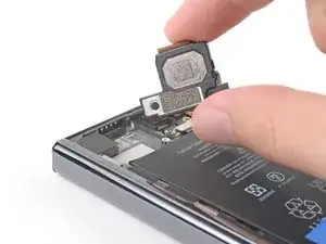
Remove the bottom speaker.
-
-
-
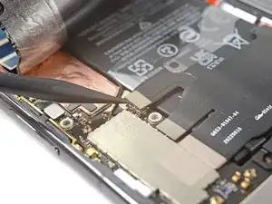
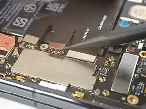
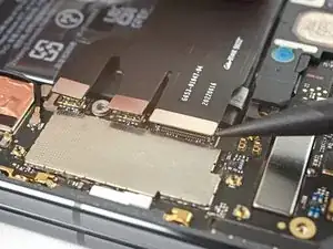
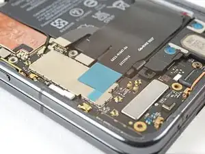
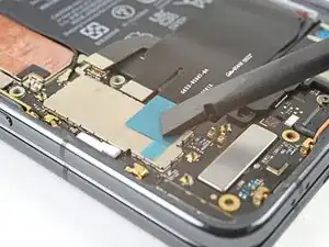
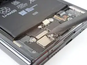
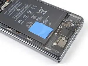
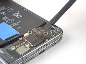
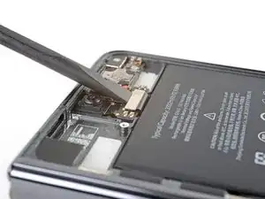
Use the point of a spudger to lift up and disconnect the fingerprint sensor press connector.
-
-
-
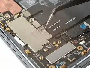
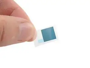
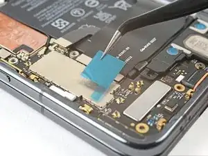
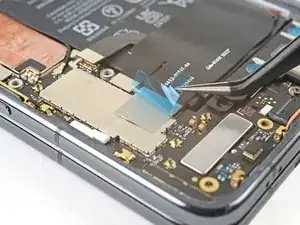
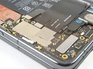
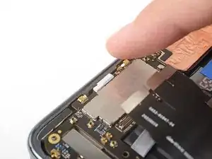
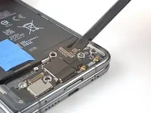
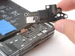
Peel off the new conductive tape from its liner and apply the sticky side to the press connector, making sure to bridge the logic board.
-
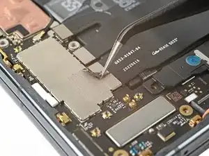
Use a spudger, or your fingers, to press down the conductive tape and adhere it.
-
Use tweezers, or your fingers, to pull on the tab and expose the tape.
-
-
-
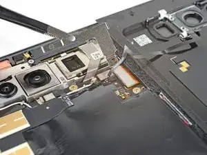
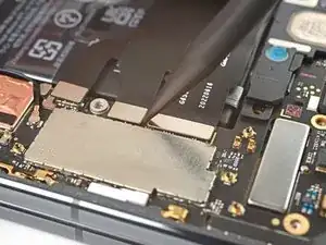
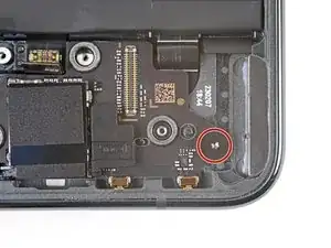
Use a Torx Plus 3IP driver to remove the two screws securing the top interconnect cable:
-
One 2.8 mm‑long screw
-
One 2.5 mm‑long screw
-
-
-
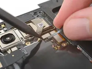
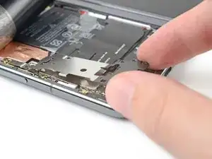
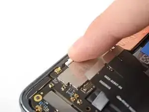
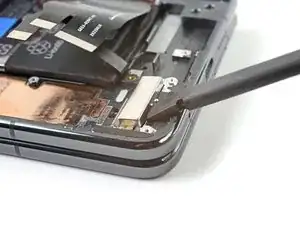
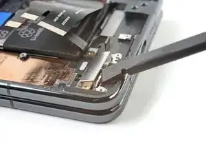
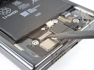
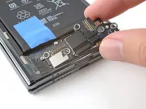
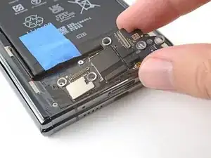
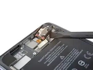
Use the point of a spudger to pry up and disconnect the top interconnect cable press connector.
-
-
-
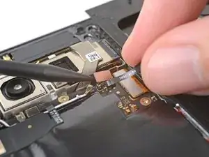
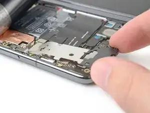
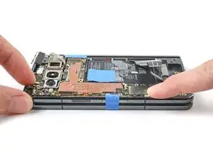
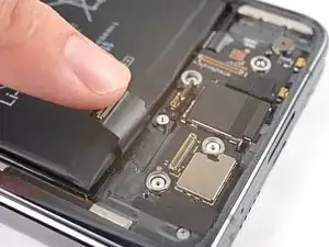
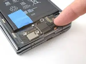
Use the flat end of a spudger to lift up and disconnect the inner screen press connector.
-
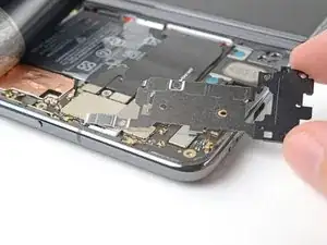
Move the inner screen cable up 90° over the right edge of the phone before continuing.
-
-
-
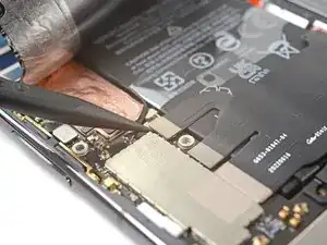
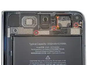
Use a Torx Plus 3IP driver to remove the two 2.8 mm‑long screws securing the middle bracket.
-
-
-
Pull the top bracket toward the left edge of the phone to release its clips.
-
Remove the top bracket.
-
During reassembly, insert the top bracket clips under their slots in the frame before aligning the screw holes.
-
-
-
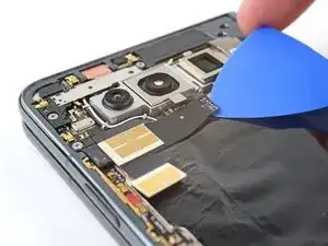
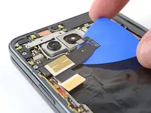
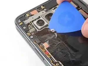
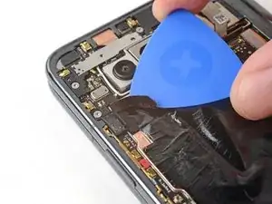
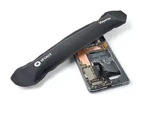
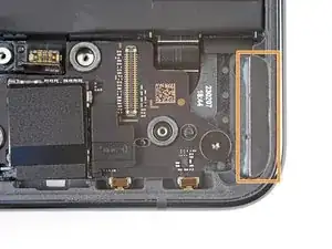
Insert the point of a spudger between the frame and the right edge of the 5G mmWave antenna.
-
Pry up to separate the adhesive.
-
-
-
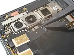
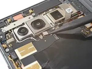
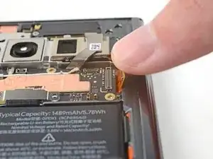
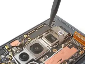
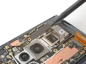
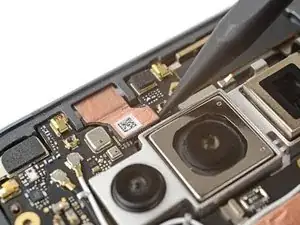
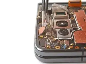
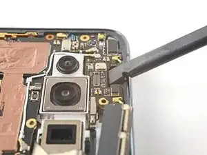
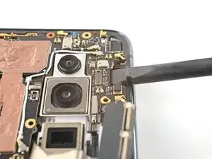
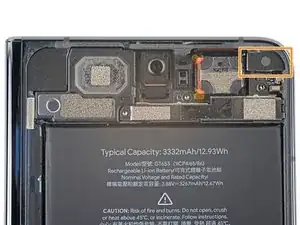
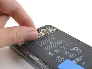
Insert the point of a spudger under the bottom right corner of the front camera press connector.
-
Pry up and disconnect the front camera press connector.
-
-
-
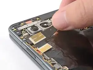
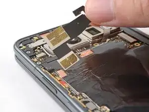
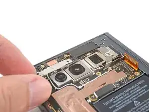
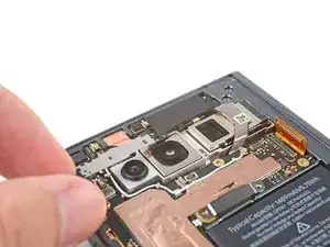
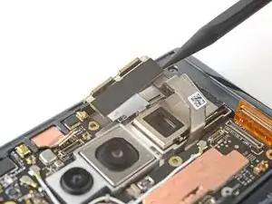
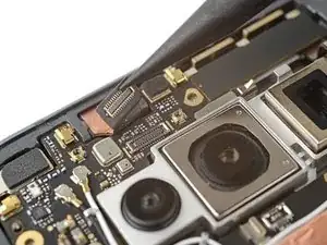
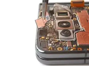
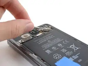
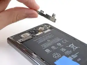
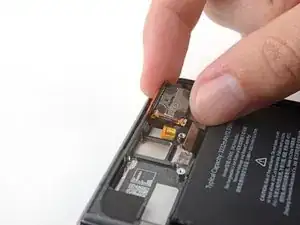
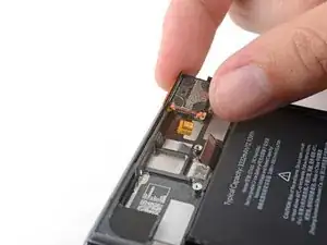
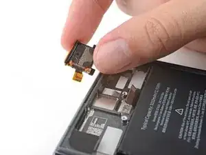
Use tweezers to grab the front camera by its connector, as close to the camera body as possible.
-
Pull straight up to separate the adhesive and remove the front camera.
-
-
-
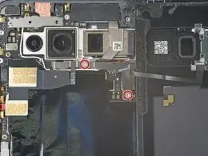
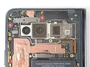
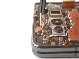
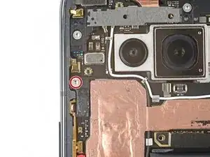
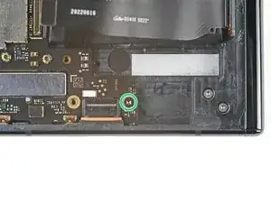
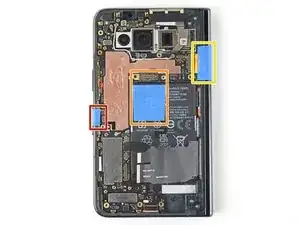
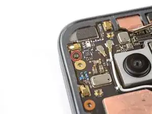
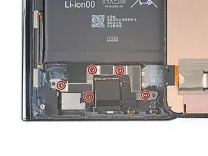
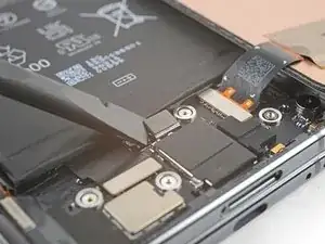
Use a Torx Plus 3IP driver to remove the two screws securing the logic board:
-
One 2.8 mm‑long screw near the top left corner
-
One 2.5 mm‑long screw near bottom right corner
-
-
-
Use tape with light adhesive, such as painter's tape, to keep the three cables out of the way before continuing:
-
Fingerprint sensor cable
-
Top interconnect cable
-
Inner screen cable
-
-
-
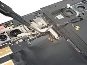
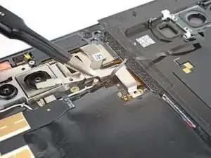
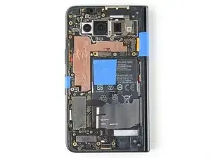
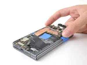
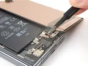
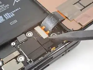
Insert the flat end of a spudger under the top of the logic board, near the front camera recess.
-
Pry up to release the logic board from its upper alignment peg.
-
-
-
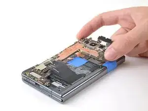
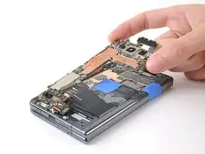
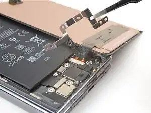
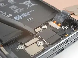
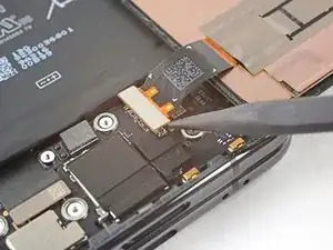
Grip the top of the logic board with your fingers.
-
Lift the logic board upward while pulling it gently toward the right edge of the phone to release the bottom clip.
-
Once the clip is released, lift straight up to remove the logic board from its lower alignment peg.
-
Remove the logic board.
-
-
-
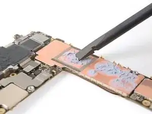
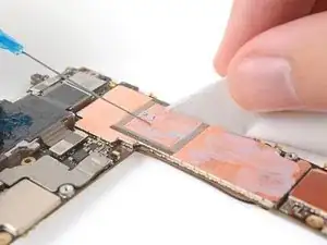
Use the flat end of a spudger to scrape off the thermal paste on the bottom of the logic board.
-
Clean any remaining thermal paste residue with isopropyl alcohol (>90%) and either a coffee filter or a lint-free cloth.
-
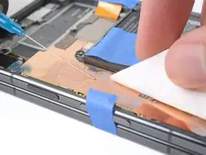
Repeat the cleaning process for the thermal paste on the frame.
-
-
-
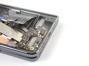
Insert the USB-C port into its cutout in the frame at a shallow angle.
-
Use your finger to press the USB-C port down until the orange rubber gasket is level with its cutout—not twisted or pinched.
-
Press the bottom of the logic board over its lower alignment peg and engage its spring connectors.
-
-
-
While pushing the logic board toward the bottom edge of the phone, press the logic board into its lower metal clip.
-
-
-
While pressing down on the white logic board bracket, push the logic board against the left edge of the phone.
-
Position the logic board over the upper alignment peg.
-
Press down to secure the logic board.
-
-
-
Insert the flat end of a spudger between the bottom of the vibrator and the frame.
-
Twist the spudger to create a gap.
-
Push the flat end of the spudger into the gap.
-
-
-
Move the flip battery and bottom interconnect cable away from the battery.
-
Use tape with light adhesive, like painter's tape, to secure the cable to the side of the phone.
-
-
-
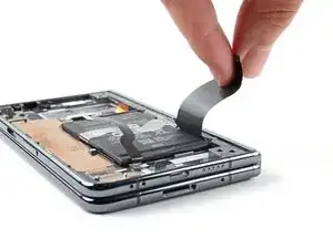
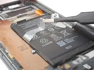
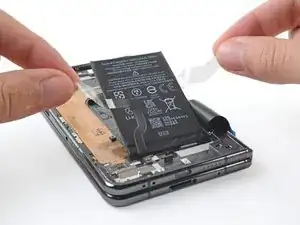
Use a pair of blunt nose tweezers, or your fingers, to peel the clear plastic pull tabs away from the battery.
-
-
-
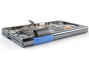
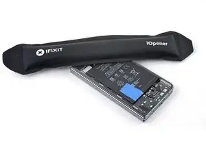
Unfold the phone and flip it over.
-
Heat an iOpener and apply it the section of the inner screen above the base battery for two minutes.
-
-
-
Close your phone.
-
Grip the ends of the plastic pull tabs with your fingers.
-
Pull straight up with constant, steady force to separate the adhesive under the battery. Work slowly and let time do the work for you until the adhesive separates.
-
If you're having trouble separating the adhesive, apply more heat and try again.
-
If you're having a lot of trouble separating the adhesive, or if you feel like you might damage the battery, follow the next five steps for an alternate method. If you were successful, jump to this step.
-
-
-
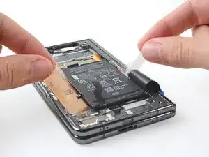
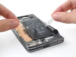
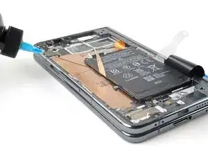
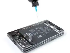
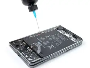
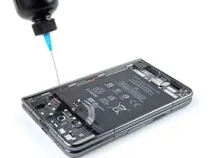
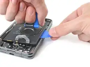
Apply a few drops of high concentration (>90%) isopropyl alcohol in the gap between the frame and the left edge of the battery.
-
-
-
Tilt the left side of the phone up to let the isopropyl alcohol flow under the battery.
-
Wait one minute for the alcohol to soften the adhesive.
-
-
-
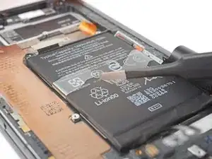
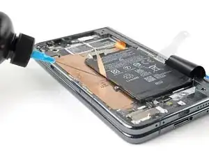
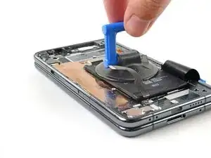
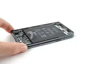
Apply a suction cup to the battery, as close to the center of the left edge as possible.
-
Pull up on the suction cup with strong, steady force to create a gap between the battery and the frame.
-
Insert an opening pick into the gap.
-
-
-
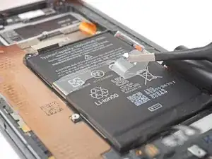
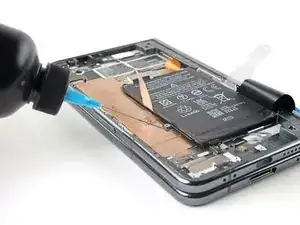
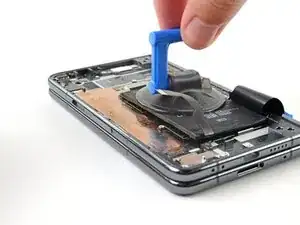
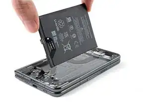
Pull up on the suction cup with strong, steady force while also prying up with the opening pick to separate the battery from the frame.
-
If you're feeling a lot of resistance, apply a few more drops of isopropyl alcohol and try again.
-
-
-
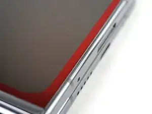
Flip over your phone so the outer screen is facing up.
-
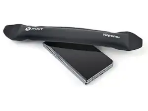
Heat an iOpener and apply it to the bottom edge of the screen for two minutes.
-
-
-
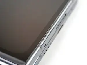
While you're waiting for the adhesive to soften, note the following:
-
The adhesive is under the dark black border surrounding the screen.
-
-
-
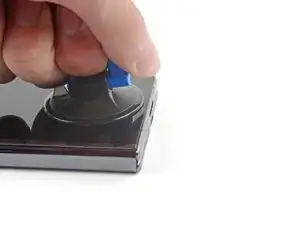
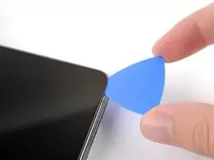
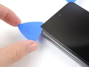
Apply a suction cup to the screen, as close to the center of the bottom edge as possible.
-
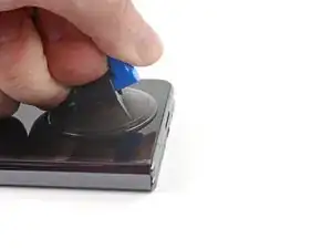
Pull up on the suction cup with strong, steady force to create a gap between the screen and the frame.
-
Insert an opening pick into the gap.
-
-
-
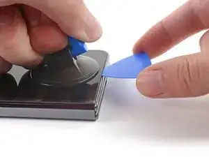
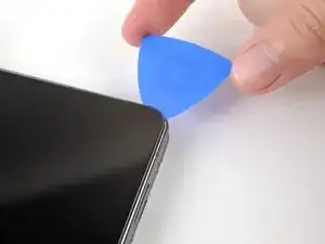
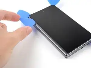
Slide the opening pick back and forth along the bottom edge to separate the adhesive.
-
Leave the opening pick in the bottom right corner before continuing.
-
-
-
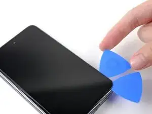
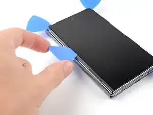
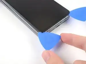
Insert a second opening pick in the bottom right corner.
-
Slide the opening pick toward the top right corner to separate the adhesive.
-
Leave the opening pick in the top right corner before continuing.
-
-
-
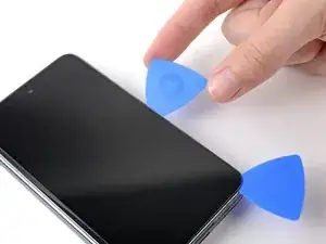
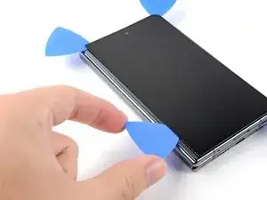
Insert a third opening pick in the top right corner.
-
Slide the opening pick toward the top left corner to separate the adhesive.
-
-
-
Angle your pick so it's as flat as possible to the screen.
-
Rotate the opening pick around the top left corner to separate the adhesive.
-
-
-
Insert a fourth opening pick in the top left corner.
-
Slide the opening pick toward the bottom left corner to separate the adhesive.
-
-
-
Angle your pick so it's as flat as possible to the screen.
-
Rotate the opening pick around the bottom left corner to separate the adhesive.
-
-
-
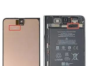
Adhesive information:
-
There's a small adhesive strip that secures the screen near the top right corner of the phone.
-
-
-
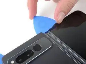
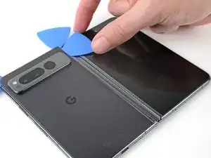
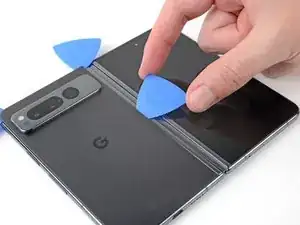
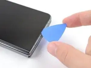
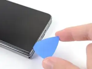
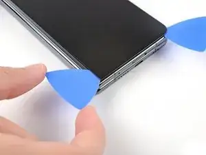
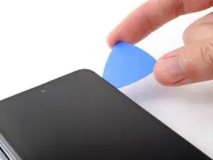
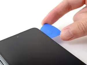
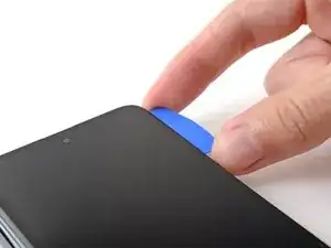
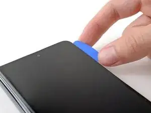
Insert an opening pick under the right edge of the screen, near the top right corner.
-
Push the opening pick under the screen as far you can go without losing your grip.
-
-
-
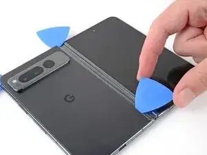
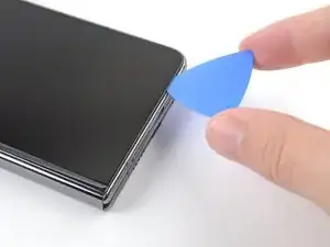
Swing the left edge of the screen up and over the right edge of the phone.
-
Let the screen rest next to the phone before continuing.
-
-
-
Use a Torx Plus 3IP screwdriver to remove the five 2.5 mm‑long screws securing the bottom bracket.
-
-
-
Insert the point of a spudger under the bottom edge of the screen press connector.
-
Pry up to disconnect the screen press connector.
-
-
-
If you're reusing your screen, use tweezers to remove big chunks of adhesive from the perimeter of the screen.
-
Repeat for any adhesive on the frame, including the small adhesive at the top right of the phone.
-
Use isopropyl alcohol (>90%) and a lint-free cloth to remove any remaining adhesive residue.
-
Follow this guide to replace your screen adhesive.
-
-
-
Use a Torx Plus 3IP screwdriver to remove the 2.2 mm‑long screw securing the lower board.
-
There's a magnet at the bottom right corner of phone. As you remove the nearby screw, it might stick to the magnet.
-
-
-
During the next step, keep the bottom interconnect cable out of the way using your hands or tape with light adhesive.
-
-
-
Use a spudger to pry up the lower board from its recess in the frame.
-
Remove the lower board.
-
-
-
Slide the left edge of the board into its left alignment peg.
-
Position the right edge of the board over its right alignment peg.
-
Push down to engage the spring connectors and secure the lower board.
-
-
-
Use a Torx Plus 3IP screwdriver to remove the three 2.5 mm‑long screws securing the top bracket.
-
There's a magnet at the top right corner of phone. As you remove nearby screws, they might stick the magnet.
-
-
-
Pull the top bracket toward the left edge of the phone to separate it from its recess in the frame.
-
Remove the top bracket.
-
-
-
Insert the flat end of a spudger between the battery and the bottom edge of the top speaker.
-
Twist the spudger to separate the adhesive securing the bottom speaker.
-
Remove the top speaker.
-
-
-
Use the flat end of spudger to pry up and disconnect the top interconnect cable press connector.
-
-
-
Pull the upper board toward the bottom of the phone to separate it from its recess in the frame
-
Remove the upper board.
-
-
-
Insert the flat end of a spudger under the bottom of the detune board.
-
Twist the spudger to separate the board from its metal clip.
-
Remove the detune board.
-
-
-
Angle the detune board downward against the right edge of the frame.
-
Press the board against the right edge of the frame to engage its spring connector.
-
Press downward to slot the board into its clip and secure it to the frame.
-
-
-
Insert the flat end of a spudger between the frame and the bottom of the earpiece speaker.
-
Twist the spudger to separate the adhesive under the body of the earpiece speaker.
-
-
-
Grab the right edge of the earpiece speaker and pull it away from the frame to separate the connector adhesive.
-
Remove the earpiece speaker.
-
-
-
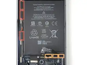
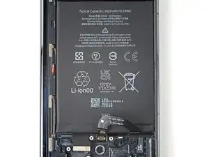
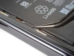
Slide an opening pick under the battery cable to separate the adhesive.
-
Use tweezers, or your fingers, to move the battery cable upward to expose the stretch-release adhesive tab under it.
-
-
-
The three along the left edge are very difficult to remove. Work slowly and avoid pulling the strips at steep angles.
-
The three along the bottom are moderately difficult to remove.
-
-
-
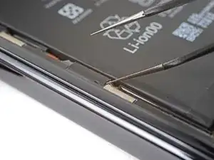
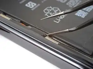
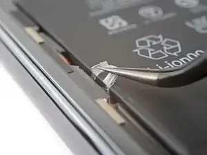
Use tweezers to peel the black pull tabs from off the frame so you can grip them with your fingers.
-
-
-
Pull each strip out slowly and steadily at a low angle. Give them plenty of time to stretch and un-stick from under the battery.
-
If any adhesive strips break off, try to retrieve them using your fingers or tweezers, and continue pulling—but don’t pry under the battery.
-
Repeat for all six stretch release adhesive strips.
-
-
-
Apply a few drops of high concentration (>90%) isopropyl alcohol in the gap between the frame and the left edge of the battery.
-
-
-
Tilt the left side of the phone up to let the isopropyl alcohol flow under the battery.
-
Wait one minute for the alcohol to soften the adhesive.
-
-
-
Apply a suction cup to the battery, as close to the center of the right edge as possible.
-
Pull up on the suction cup with strong, steady force to create a gap between the battery and the frame.
-
Insert an opening pick into the gap.
-
-
-
Pull up on the suction cup with strong, steady force while also prying up with the opening pick to separate the battery from the frame.
-
If you're feeling a lot of resistance, apply a few more drops of isopropyl alcohol and try again.
-
-
-
If your bottom interconnect cable is still taped down, remove the tape now.
-
Lift the battery out its recess and remove it.
-


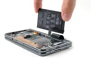
For optimal performance, calibrate your newly installed battery after completing this guide.
Take your e-waste to an R2 or e-Stewards certified recycler.
Compare your new replacement part to the original part—you may need to transfer remaining components or remove adhesive backings from the new part before you install it.
To reassemble your device, follow these instructions in reverse order.
To run a diagnostics test with the built-in Pixel Diagnostic tool, click here.
Repair didn’t go as planned? Try some basic troubleshooting, or ask our Google Pixel Fold Answers Community for help.

2 comments
aaaaaaaaaaaaaaaaaaaa
good lord
i thought apple was bad
but 126 steps??????!!??!???
shingle -
"Um dein Gerät wieder zusammenzubauen, befolge diese Anweisungen in umgekehrter Reihenfolge."
Diese Anmerkung ist eine Zumutung!
Bei einer solch komplexen Reparatur hätte ich erwartet, dass der ZUSAMMENBAU, dh. das Einfügen der ausgebauten Teile in die neue Displayeinheit genauso ausführlich beschrieben wird ("Step By Step") wie der Ausbau der Komponenten.
Ausserdem fehlen beim Reparaturset 2 wesentliche Teile, nämlich die leitfähigen Klebebänder (Schritte 32 und 43). Im Prinzip sind das "Cent-Artikel*, die nicht im Reparaturset von sage und schreibe 900 € enthalten waren! Ich musste daher die doch langwierige Reparatur (ca. 4h) an dieser Stelle abbrechen und warte jetzt auf die nachträglich bestellten Artikel von knapp 10 €. Das ist extrem ärgerlich.
Ansonsten ist die Reparaturanleitung wirklich sehr gut beschreiben, die Durchführung mit einem einigermassen handwerklichen Geschick auch machbar. Es braucht Geduld, insbesondere beim Trennen der verklebten Glasrückwand und des äusseren Displays.
Hardy -