Track geometry
Track geometry is three-dimensional geometry of track layouts and associated measurements used in design, construction and maintenance of railroad tracks. The subject is used in the context of standards, speed limits and other regulations in the areas of track gauge, alignment, elevation, curvature and track surface.[1] Although, the geometry of the tracks is three-dimensional by nature, the standards are usually expressed in two separate layouts for horizontal and vertical.

| Track gauge | ||||||||||||||||||||||||||||||||||||||||||||||||||||||||||||||||||||||||||||||||||||||||
|---|---|---|---|---|---|---|---|---|---|---|---|---|---|---|---|---|---|---|---|---|---|---|---|---|---|---|---|---|---|---|---|---|---|---|---|---|---|---|---|---|---|---|---|---|---|---|---|---|---|---|---|---|---|---|---|---|---|---|---|---|---|---|---|---|---|---|---|---|---|---|---|---|---|---|---|---|---|---|---|---|---|---|---|---|---|---|---|---|
| By transport mode | ||||||||||||||||||||||||||||||||||||||||||||||||||||||||||||||||||||||||||||||||||||||||
|
Tram · Rapid transit Miniature · Scale model |
||||||||||||||||||||||||||||||||||||||||||||||||||||||||||||||||||||||||||||||||||||||||
| By size (list) | ||||||||||||||||||||||||||||||||||||||||||||||||||||||||||||||||||||||||||||||||||||||||
|
||||||||||||||||||||||||||||||||||||||||||||||||||||||||||||||||||||||||||||||||||||||||
| Change of gauge | ||||||||||||||||||||||||||||||||||||||||||||||||||||||||||||||||||||||||||||||||||||||||
|
Break-of-gauge · Dual gauge · Conversion (list) · Bogie exchange · Variable gauge |
||||||||||||||||||||||||||||||||||||||||||||||||||||||||||||||||||||||||||||||||||||||||
| By location | ||||||||||||||||||||||||||||||||||||||||||||||||||||||||||||||||||||||||||||||||||||||||
|
North America · South America · Europe · Australia 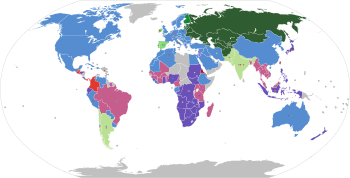 |
||||||||||||||||||||||||||||||||||||||||||||||||||||||||||||||||||||||||||||||||||||||||
Layout
Horizontal layout
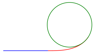
Horizontal layout is the track layout on the horizontal plane. This can be thought of as the plan view which is a view of a 3-dimensional track from the position above the track. In track geometry, the horizontal layout involves the layout of three main track types: tangent track (straight line), curved track, and track transition curve (also called transition spiral or spiral) which connects between a tangent and a curved track.
In Australia, there is a special definition for a bend (or a horizontal bend) which is a connection between two tangent tracks at almost 180 degrees (with deviation not more than 1 degree 50 minutes) without an intermediate curve. There is a set of speed limits for the bends separately from normal tangent track.[2]
Vertical layout
Vertical layout is the track layout on the vertical plane. This can be thought of as the elevation view which is the side view of the track to show track elevation. In track geometry, the vertical layout involves concepts such as crosslevel, cant and gradient.
Reference rail
The reference rail is the base rail that is used as a reference point for the measurement. It can vary in different countries. Most countries use one of the rails as the reference rail. For example, the United States uses the reference rail as the line rail which is the east rail of tangent track running north and south, the north rail of tangent track running east and west, the outer rail (the rail that is further away from the center) on curves, or the outside rails in multiple track territory.[3] For Swiss railroad, the reference rail for tangent track is the center line between two rails, but it is the outside rail for curved track.[4]
Track gauge
Track gauge or rail gauge (also known as track gage in the United States[5]) is the distance between the inner sides (gauge sides) of the heads of the two load bearing rails that make up a single railway line. Each country uses different gauges for different types of trains. However, the 1,435 mm (4 ft 8 1⁄2 in) gauge is the basis of 60% of the world's railways.
Transverse elevation
Crosslevel

Crosslevel (or 'cross level') is the measurement of the difference in elevation (height) between the top surface of the two rails at any point of railroad track. The two points (each at the head of each rail) are measured at by the right angles to the reference rail. Since the rail can slightly move up and down, the measurement should be done under load.
It is said to be zero crosslevel when there is no difference in elevation of both rails. It is said to be reverse crosslevel when the outside rail of curved track has lower elevation than the inside rail. Otherwise, the crosslevel is expressed in the unit of height.
The speed limits are governed by the crosslevel of the track. In tangent track, it is desired to have zero crosslevel. However, the deviation from zero can take place. Many regulations have specification related to speed limits of certain segment of the track based on the crosslevel.[5][6]
For curved track, most countries use the term cant or superelevation to express the difference in elevation and related regulations.
Warp
Warp is the difference in crosslevel of any two points within the specific distance along the track. The warp parameter in the track geometry is used to specify the maximum in the crosslevel difference of the track in any segment (tangents, curves and spirals).
Without the maximum warp parameter, the regulation on crosslevel alone may not be sufficient. Consider rails with a positive crosslevel followed by a negative crosslevel followed by a sequence of alternating positive and negative crosslevels. Although, all of those crosslevels are in permissible parameter, when operating a train along such track, the motion will be rocking left and right. Therefore, the maximum warp parameter is used to prevent the critical harmonic rock-off condition that may result in the trains rocking back and forth and derailing following wheel climb.[6]
In the United States, the specific distance used for measurement to ensure that the difference in crosslevel of the track is within the permissible warp parameter is 62 feet. The design warp is zero for both tangent and curved track. That means, ideally, the crosslevel should not change between any two points within 62 feet. There are some deviations to allow crosslevels along the track to change (such as change for superelevation in curves). Different levels of those deviations from the zero warp specify the speed limits.[5]
The specification that focuses on the rate of change in crosslevels of curved track is contained within the area related to cant gradient.
Longitudinal elevation
Track gradient
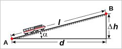
Δh = rise
l = slope length
α = angle of inclination
The term track gradient is relative elevation of the two rails along the track. This can be expressed in the distance traveled horizontally for a rise of one unit, or in terms of an angle of inclination or a percentage difference in elevation for a given distance of the track.
The allowable gradients may be based on the ruling gradient which is the maximum gradient over which a tonnage train can be hauled with one locomotive. In some countries, momentum gradient which is a steeper but shorter gradient may be allowed. This is usually when there is a track gradient is connected to a leveled tangent track that is long enough with no signal between them so that train can build momentum to push through steeper grade than it can be without momentum.
In curved track (with or without cant), there will be curve resistance to push the trains through the curve. The allowable gradients may be reduced on curves to compensate for the extra curve resistance.[2] The gradient should be uniform along the track.
Vertical curve
Vertical curve is the curve in vertical layout to connect two track gradients together whether it is for changing from an upgrade to a downgrade (summit), changing from a downgrade to an upgrade (sag or valley), changing in two levels of upgrades or changing in two levels of downgrades.
Some countries do not have specification on the exact geometry of vertical curves beyond general specification on vertical alignment. Australia has specification that the shape of vertical curves should be based on quadratic parabola but the length of a given vertical curve is calculated based on circular curve.[2]
Curvature
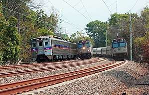
In most countries, the measurement of curvature of curved track is expressed in radius. The shorter the radius, the sharper the curve is. For sharper curves, the speed limits are lower to prevent an outward horizontal centrifugal force to overturn the trains by directing its weight toward the outside rail. Cant may be used to allow higher speeds over the same curve.
In the United States, the measurement of curvature is expressed in degree of curvature. This is done by having a chord of 100 feet (30.48 m) connecting to two points on an arc of the reference rail, then drawing radii from the center to each of the chord end points. The angle between the radii lines is the degree of curvature.[7] The degree of curvature is inverse of radius. The larger the degree of curvature, the sharper the curve is. Expressing the curve in this way allows surveyors to use estimation and simpler tools in curve measurement. This can be done by using a 62-foot (18.90 m) string line to be a chord to connect the arc at the gage side of the reference rail. Then at the midpoint of the string line (at the 31st foot), a measurement is taken from the string line to the gauge of the reference rail. The number of inches in that measurement is approximated to be the number of degrees of curvature.[5]
Due to the limitation of how specific train equipment can make a turn at maximum speeds, there is a limitation of minimum curve radius to control the sharpness of all curves along a given route. Although most countries use radius for measurement of curvature, the term maximum degree of curvature is still used outside of the United States such as in India, but with the radius as the unit.[8]
Cant
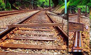
In curved track, it is usually designed to raise the outer rail, providing a banked turn, thus allowing trains to maneuver through the curve at higher speeds that would otherwise be not possible if the surface was flat or level. It also helps a train steer around a curve, keeping the wheel flanges from pressing the rails, minimizing friction and wear. The measurement of the difference in elevation between the outer rail and the inner rail is called cant in most countries. Sometime the cant is measured in term of angle instead of height difference.[9] In the United States, it is measured in height difference and called crosslevel, even for the curved track.
When the outside rail is at higher elevation than the inside rail, it is called positive cant. This is normally the desired layout for curved track. Most counties achieve the desired level of positive cant by raising the outside rail to that level which is called superelevation. For Swiss railroads, the cant is done by rotating at the track axis (center of the two rails) to have outside rail super elevated (raised) at the half rate of the desired cant and the inside rail under elevated (lowered) at the same half rate of the desired cant.
When the outside rail is at lower elevation than the inside rail, it is called negative cant (or reverse crosslevel in the United States). This is not usually a desired layout but it may be unavoidable in some situations such as curves involving turnouts.
There are regulations which limit the maximum cant. This is to control the unloading of the wheels on the outside rail (high rail), especially at low speeds.
Cant gradient
Cant gradient is the amount by which cant is increased or decreased in a given length of track. The change in cant is required in order to connect a tangent track (no cant) to a curved track (with cant) through a transition curve. The rate of change of cant is used to determine the suitable cant gradient for a given design speed. Track twist may also be used to describe cant gradient which may be expressed in percentage of cant change per length unit.[4] However, in the UK, the term track twist is normally used in the context of cant gradient with higher values which are considered to be faults.[9]
In the United States, the required cant gradient on a transition curve to achieve smooth connection between superelevation of curved track and the zero crosslevel of tangent track is called superelevation runoff. In addition to the runoff specification, the regulations related to allowable rate of change in the cant is also part of the general specification on the rate of change in crosslevel called warp parameter. The warp parameter and superelevation runoff help calculate the required length of the runoff for a transition curve.[6]
Cant deficiency
As described, cant may be used to reduce lateral acceleration on trains traveling on curved track. This is to balance the centrifugal force (force pushing outward the curve) and centripetal force (force pushing inward the curve). At a higher speed, the centrifugal force is higher. On the contrary, higher cant creates the higher centripetal force. The calculation for this assumes a constant train speed on a constant radius curve.
When the speed of the train and the amount of cant are in balance (centrifugal matches centripetal), it is called equilibrium. This would make the components of wheel to rail force normal to the plane of the track having the same in aggregate for the outside rail as for the inside rail. This would also make the passengers in the train not to perceive any lateral acceleration (a push toward sideway).
For a fixed amount of cant, the speed that creates balance is called equilibrium speed. For a constant speed of a running train, the amount of required cant to achieve the balance is called equilibrium cant.[9]
In practice, trains are not running on equilibrium cants at curves. The situation is called unbalance, which can be in one of the two following ways. For a given speed, if the actual cant is less than the equilibrium cant, the amount of cant difference is called cant deficiency. In the other word, it is the amount of missing cant to achieve the balance. On the contrary, for a given speed, if the actual cant is higher than the equilibrium cant, the amount of over cant from the balance is called cant excess.
In a shared track configuration for trains with different operating speeds such as freight and higher-speed rail passenger services, the cant on a curve should be considered for both high and low speeds. The higher-speed trains would experience cant deficiency and the lower-speed trains would experience cant excess. These parameters have a significant effect on curve performance which includes safety, passenger comfort, and wear and tear of equipment and rails.[10]
Alignment
The term alignment is used in both horizontal and vertical layouts to describe the line uniformity (straightness) of the rails.
The horizontal alignment (or alinement in the United States) is done by using a predefined length of string line (such as 62-foot in the US and 20 meters in Australia[2]) to measure along the gauge side of the reference rail. It is the distance (in inches or millimeters) from the midpoint of the string line to the gauge of the reference rail. The design horizontal alignment for tangent track is zero (perfect straight line on the horizontal layout). The design horizontal alignment on the curved track in the United States is 1 inch for each degree of curvature. Any other readings indicate deviations.
The vertical alignment (or profile in the United States, but not to be confused with rail profile) is the surface uniformity in the vertical plane. The measurement of uniformity is done using a predefined length of string line (normally the same length used in horizontal alignment) along the track. If the midpoint of the measurement has higher elevation, it is called hump deviation. On the other hand, if the midpoint has lower elevation, it is called dip deviation.[6]
These deviations from design alignment are used as parameters to assign speed limits.
See also
- Track geometry car
- Jim crow, a tool for bending rails
References
- "Federal Railroad Administration Federal Track Safety Standards Fact Sheet" (PDF). Federal Railroad Administration. Retrieved 8 November 2012.
- PART 1025 Track Geometry (Issue 2 – 07/10/08 ed.). Department of Planning Transport, and Infrastructure - Government of South Australia. 2008.
- "Railroad Glossary and Definitions". Allen Railroad. Retrieved 12 November 2012.
- Glaus, Ralph (2006). "2". The Swiss Trolley – A Modular System for Track Surveying (PDF). ISBN 3-908440-13-0.
- "12". Railroad Track Standards (TM 5-628/AFR 91-44) (PDF). United States Army and United States Air Force. April 1991. pp. 12-1–12-5. Archived from the original (PDF) on 27 March 2014. Retrieved 12 November 2012.
- "5". Federal Railroad Administration Track Safety Standards Compliance Manual (PDF). Federal Railroad Administration. 1 April 2007. Archived from the original (PDF) on 28 May 2008. Retrieved 13 November 2012.
- "Measuring track curvature". ASK TRAINS. Trains magazine. Retrieved 13 November 2012.
- Mundrey, J.S. (2000). Railway track engineering (3rd ed.). New Delhi: Tata McGraw-Hill Pub. p. 165. ISBN 978-0-07-463724-1. Retrieved 14 November 2012.
- Track Standards Manual - Section 8: Track Geometry (PDF). Railtrack PLC. December 1998. Retrieved 13 November 2012.
- Klauser, Peter (October 2005). "Operating at High Cant Deficiency". Interface - The Journal of Wheel/Rail Interaction.
