Tomography
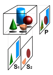
Tomography is imaging by sections or sectioning through the use of any kind of penetrating wave. The method is used in radiology, archaeology, biology, atmospheric science, geophysics, oceanography, plasma physics, materials science, astrophysics, quantum information, and other areas of science. The word tomography is derived from Ancient Greek τόμος tomos, "slice, section" and γράφω graphō, "to write" or, in this context as well, " to describe." A device used in tomography is called a tomograph, while the image produced is a tomogram.


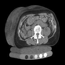
In many cases, the production of these images is based on the mathematical procedure tomographic reconstruction, such as X-ray computed tomography technically being produced from multiple projectional radiographs. Many different reconstruction algorithms exist. Most algorithms fall into one of two categories: filtered back projection (FBP) and iterative reconstruction (IR). These procedures give inexact results: they represent a compromise between accuracy and computation time required. FBP demands fewer computational resources, while IR generally produces fewer artifacts (errors in the reconstruction) at a higher computing cost.[1]
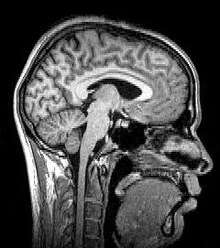
Although MRI and ultrasound are transmission methods, they typically do not require movement of the transmitter to acquire data from different directions. In MRI, both projections and higher spatial harmonics are sampled by applying spatially-varying magnetic fields; no moving parts are necessary to generate an image. On the other hand, since ultrasound uses time-of-flight to spatially encode the received signal, it is not strictly a tomographic method and does not require multiple acquisitions at all.
Types of tomography
Some recent advances rely on using simultaneously integrated physical phenomena, e.g. X-rays for both CT and angiography, combined CT/MRI and combined CT/PET.
Discrete tomography and Geometric tomography, on the other hand, are research areas that deal with the reconstruction of objects that are discrete (such as crystals) or homogeneous. They are concerned with reconstruction methods, and as such they are not restricted to any of the particular (experimental) tomography methods listed above.
Synchrotron X-ray tomographic microscopy
A new technique called synchrotron X-ray tomographic microscopy (SRXTM) allows for detailed three-dimensional scanning of fossils.[11]
The construction of third-generation synchrotron sources combined with the tremendous improvement of detector technology, data storage and processing capabilities since the 1990s has led to a boost of high-end synchrotron tomography in materials research with a wide range of different applications, e.g. the visualization and quantitative analysis of differently absorbing phases, microporosities, cracks, precipitates or grains in a specimen. Synchrotron radiation is created by accelerating free particles in high vacuum. By the laws of electrodynamics this acceleration leads to the emission of electromagnetic radiation (Jackson, 1975). Linear particle acceleration is one possibility, but apart from the very high electric fields one would need it is more practical to hold the charged particles on a closed trajectory in order to obtain a source of continuous radiation. Magnetic fields are used to force the particles onto the desired orbit and prevent them from flying in a straight line. The radial acceleration associated with the change of direction then generates radiation.[12]
Volume rendering

Volume rendering is a set of techniques used to display a 2D projection of a 3D discretely sampled data set, typically a 3D scalar field. A typical 3D data set is a group of 2D slice images acquired, for example, by a CT, MRI, or MicroCT scanner. These are usually acquired in a regular pattern (e.g., one slice every millimeter) and usually have a regular number of image pixels in a regular pattern. This is an example of a regular volumetric grid, with each volume element, or voxel represented by a single value that is obtained by sampling the immediate area surrounding the voxel.
To render a 2D projection of the 3D data set, one first needs to define a camera in space relative to the volume. Also, one needs to define the opacity and color of every voxel. This is usually defined using an RGBA (for red, green, blue, alpha) transfer function that defines the RGBA value for every possible voxel value.
For example, a volume may be viewed by extracting isosurfaces (surfaces of equal values) from the volume and rendering them as polygonal meshes or by rendering the volume directly as a block of data. The marching cubes algorithm is a common technique for extracting an isosurface from volume data. Direct volume rendering is a computationally intensive task that may be performed in several ways.
History
Focal plane tomography was developed in the 1930s by the radiologist Alessandro Vallebona, and proved useful in reducing the problem of superimposition of structures in projectional radiography. In a 1953 article in the medical journal Chest, B. Pollak of the Fort William Sanatorium described the use of planography, another term for tomography.[13] Focal plane tomography remained the conventional form of tomography until being largely replaced by mainly computed tomography the late-1970s.[14] Focal plane tomography uses the fact that the focal plane appears sharper, while structures in other planes appear blurred. By moving an X-ray source and the film in opposite directions during the exposure, and modifying the direction and extent of the movement, operators can select different focal planes which contain the structures of interest.
See also
![]()
- Chemical imaging
- 3D reconstruction
- Discrete tomography
- Geometric tomography
- Geophysical imaging
- Industrial CT scanning
- Johann Radon
- Medical imaging
- MRI compared with CT
- Network tomography
- Nonogram, a type of puzzle based on a discrete model of tomography
- Radon transform
- Tomographic reconstruction
- Multiscale Tomography
- Voxels
References
- Herman, G. T., Fundamentals of computerized tomography: Image reconstruction from projection, 2nd edition, Springer, 2009
- Ralf Habel, Michael Kudenov, Michael Wimmer: Practical Spectral Photography
- J. Floyd, P. Geipel, A. M. Kempf (2011). "Computed Tomography of Chemiluminescence (CTC): Instantaneous 3D measurements and Phantom studies of a turbulent opposed jet flame". Combustion and Flame. 158 (2): 376–391. doi:10.1016/j.combustflame.2010.09.006.CS1 maint: multiple names: authors list (link)
- Floyd J (2011). "Computed Tomography of Chemiluminescence (CTC): Instantaneous 3D measurements and Phantom studies of a turbulent opposed jet flame". Combustion and Flame. 158 (2): 376–391. doi:10.1016/j.combustflame.2010.09.006.
- K. Mohri, S. Görs, J. Schöler, A. Rittler, T. Dreier, C. Schulz, A. Kempf (2017). "Instantaneous 3D imaging of highly turbulent flames using computed tomography of chemiluminescence". Applied Optics. 156 (26): 7385–7395. Bibcode:2017ApOpt..56.7385M. doi:10.1364/AO.56.007385. PMID 29048060.CS1 maint: multiple names: authors list (link)
- Huang, S M; Plaskowski, A; Xie, C G; Beck, M S (1988). "Capacitance-based tomographic flow imaging system". Electronics Letters. 24 (7): 418–19.
- Crowther, R. A.; DeRosier, D. J.; Klug, A.; S, F. R. (1970-06-23). "The reconstruction of a three-dimensional structure from projections and its application to electron microscopy". Proc. R. Soc. Lond. A. 317 (1530): 319–340. Bibcode:1970RSPSA.317..319C. doi:10.1098/rspa.1970.0119. ISSN 0080-4630.
- Electron tomography : methods for three-dimensional visualization of structures in the cell. Frank, J. (Joachim), 1940- (2nd ed.). New York: Springer. 2006. pp. 3. ISBN 9780387690087. OCLC 262685610.CS1 maint: others (link)
- Martin; et al. (2013). "3D spectral imaging with synchrotron Fourier transform infrared spectro-microtomography". Nature Methods. 10 (9): 861–864. doi:10.1038/nmeth.2596. PMID 23913258.
- Ahadi Mojtaba, Isa Maryam, Saripan M. Iqbal, Hasan W. Z. W. (2015). "Three dimensions localization of tumors in confocal microwave imaging for breast cancer detection". Microwave and Optical Technology Letters. 57 (12): 2917–2929. doi:10.1002/mop.29470.CS1 maint: multiple names: authors list (link)
- Donoghue; et al. (Aug 10, 2006). "Synchrotron X-ray tomographic microscopy of fossil embryos (letter)". Nature. 442 (7103): 680–683. Bibcode:2006Natur.442..680D. doi:10.1038/nature04890. PMID 16900198.
- Banhart, John, ed. Advanced Tomographic Methods in Materials Research and Engineering. Monographs on the Physics and Chemistry of Materials. Oxford ; New York: Oxford University Press, 2008.
- Pollak, B. (December 1953). "Experiences with Planography". Chest. 24 (6): 663–669. doi:10.1378/chest.24.6.663. ISSN 0012-3692. PMID 13107564. Archived from the original on 2013-04-14. Retrieved July 10, 2011.
- Littleton, J.T. "Conventional Tomography" (PDF). A History of the Radiological Sciences. American Roentgen Ray Society. Retrieved 29 November 2014.