Wavelength
In physics, the wavelength is the spatial period of a periodic wave—the distance over which the wave's shape repeats.[1][2] It is the distance between consecutive corresponding points of the same phase on the wave, such as two adjacent crests, troughs, or zero crossings, and is a characteristic of both traveling waves and standing waves, as well as other spatial wave patterns.[3][4] The inverse of the wavelength is called the spatial frequency. Wavelength is commonly designated by the Greek letter lambda (λ). The term wavelength is also sometimes applied to modulated waves, and to the sinusoidal envelopes of modulated waves or waves formed by interference of several sinusoids.[5]
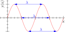
Assuming a sinusoidal wave moving at a fixed wave speed, wavelength is inversely proportional to frequency of the wave: waves with higher frequencies have shorter wavelengths, and lower frequencies have longer wavelengths.[6]
Wavelength depends on the medium (for example, vacuum, air, or water) that a wave travels through. Examples of waves are sound waves, light, water waves and periodic electrical signals in a conductor. A sound wave is a variation in air pressure, while in light and other electromagnetic radiation the strength of the electric and the magnetic field vary. Water waves are variations in the height of a body of water. In a crystal lattice vibration, atomic positions vary.
The range of wavelengths or frequencies for wave phenomena is called a spectrum. The name originated with the visible light spectrum but now can be applied to the entire electromagnetic spectrum as well as to a sound spectrum or vibration spectrum.
Sinusoidal waves
In linear media, any wave pattern can be described in terms of the independent propagation of sinusoidal components. The wavelength λ of a sinusoidal waveform traveling at constant speed v is given by[7]
where v is called the phase speed (magnitude of the phase velocity) of the wave and f is the wave's frequency. In a dispersive medium, the phase speed itself depends upon the frequency of the wave, making the relationship between wavelength and frequency nonlinear.
In the case of electromagnetic radiation—such as light—in free space, the phase speed is the speed of light, about 3×10⁸ m/s. Thus the wavelength of a 100 MHz electromagnetic (radio) wave is about: 3×10⁸ m/s divided by 108 Hz = 3 metres. The wavelength of visible light ranges from deep red, roughly 700 nm, to violet, roughly 400 nm (for other examples, see electromagnetic spectrum).
For sound waves in air, the speed of sound is 343 m/s (at room temperature and atmospheric pressure). The wavelengths of sound frequencies audible to the human ear (20 Hz–20 kHz) are thus between approximately 17 m and 17 mm, respectively. Somewhat higher frequencies are used by bats so they can resolve targets smaller than 17 mm. Wavelengths in audible sound are much longer than those in visible light.
Standing waves
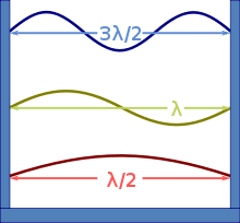
A standing wave is an undulatory motion that stays in one place. A sinusoidal standing wave includes stationary points of no motion, called nodes, and the wavelength is twice the distance between nodes.
The upper figure shows three standing waves in a box. The walls of the box are considered to require the wave to have nodes at the walls of the box (an example of boundary conditions) determining which wavelengths are allowed. For example, for an electromagnetic wave, if the box has ideal metal walls, the condition for nodes at the walls results because the metal walls cannot support a tangential electric field, forcing the wave to have zero amplitude at the wall.
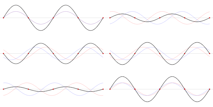
The stationary wave can be viewed as the sum of two traveling sinusoidal waves of oppositely directed velocities.[8] Consequently, wavelength, period, and wave velocity are related just as for a traveling wave. For example, the speed of light can be determined from observation of standing waves in a metal box containing an ideal vacuum.
Mathematical representation
Traveling sinusoidal waves are often represented mathematically in terms of their velocity v (in the x direction), frequency f and wavelength λ as:
where y is the value of the wave at any position x and time t, and A is the amplitude of the wave. They are also commonly expressed in terms of wavenumber k (2π times the reciprocal of wavelength) and angular frequency ω (2π times the frequency) as:
in which wavelength and wavenumber are related to velocity and frequency as:
or
In the second form given above, the phase (kx − ωt) is often generalized to (k•r − ωt), by replacing the wavenumber k with a wave vector that specifies the direction and wavenumber of a plane wave in 3-space, parameterized by position vector r. In that case, the wavenumber k, the magnitude of k, is still in the same relationship with wavelength as shown above, with v being interpreted as scalar speed in the direction of the wave vector. The first form, using reciprocal wavelength in the phase, does not generalize as easily to a wave in an arbitrary direction.
Generalizations to sinusoids of other phases, and to complex exponentials, are also common; see plane wave. The typical convention of using the cosine phase instead of the sine phase when describing a wave is based on the fact that the cosine is the real part of the complex exponential in the wave
General media
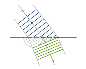
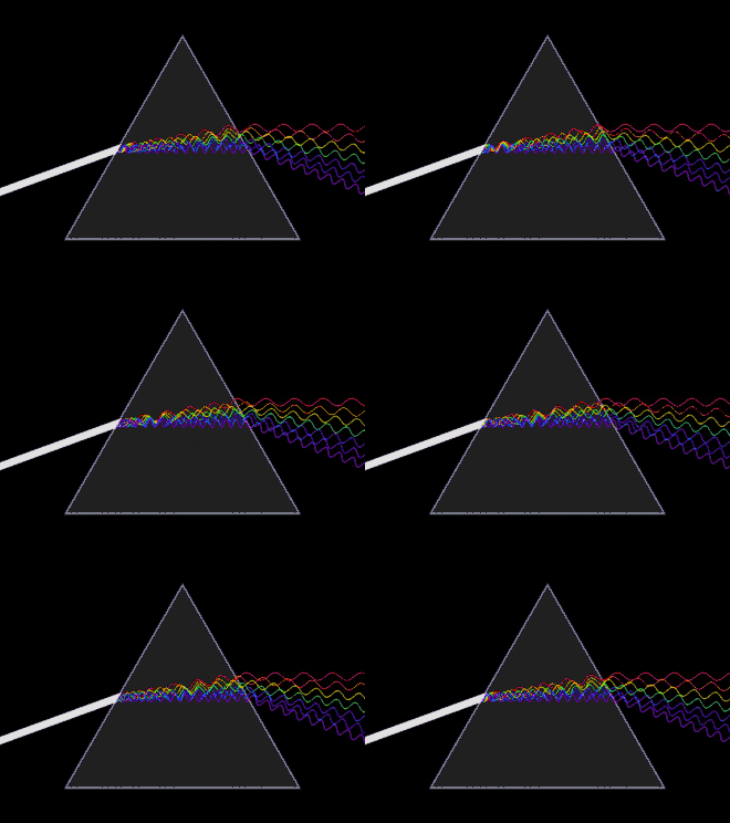
The speed of a wave depends upon the medium in which it propagates. In particular, the speed of light in a medium is less than in vacuum, which means that the same frequency will correspond to a shorter wavelength in the medium than in vacuum, as shown in the figure at right.
This change in speed upon entering a medium causes refraction, or a change in direction of waves that encounter the interface between media at an angle.[9] For electromagnetic waves, this change in the angle of propagation is governed by Snell's law.
The wave velocity in one medium not only may differ from that in another, but the velocity typically varies with wavelength. As a result, the change in direction upon entering a different medium changes with the wavelength of the wave.
For electromagnetic waves the speed in a medium is governed by its refractive index according to
where c is the speed of light in vacuum and n(λ0) is the refractive index of the medium at wavelength λ0, where the latter is measured in vacuum rather than in the medium. The corresponding wavelength in the medium is
When wavelengths of electromagnetic radiation are quoted, the wavelength in vacuum usually is intended unless the wavelength is specifically identified as the wavelength in some other medium. In acoustics, where a medium is essential for the waves to exist, the wavelength value is given for a specified medium.
The variation in speed of light with vacuum wavelength is known as dispersion, and is also responsible for the familiar phenomenon in which light is separated into component colors by a prism. Separation occurs when the refractive index inside the prism varies with wavelength, so different wavelengths propagate at different speeds inside the prism, causing them to refract at different angles. The mathematical relationship that describes how the speed of light within a medium varies with wavelength is known as a dispersion relation.
Nonuniform media

Wavelength can be a useful concept even if the wave is not periodic in space. For example, in an ocean wave approaching shore, shown in the figure, the incoming wave undulates with a varying local wavelength that depends in part on the depth of the sea floor compared to the wave height. The analysis of the wave can be based upon comparison of the local wavelength with the local water depth.[10]

Waves that are sinusoidal in time but propagate through a medium whose properties vary with position (an inhomogeneous medium) may propagate at a velocity that varies with position, and as a result may not be sinusoidal in space. The figure at right shows an example. As the wave slows down, the wavelength gets shorter and the amplitude increases; after a place of maximum response, the short wavelength is associated with a high loss and the wave dies out.
The analysis of differential equations of such systems is often done approximately, using the WKB method (also known as the Liouville–Green method). The method integrates phase through space using a local wavenumber, which can be interpreted as indicating a "local wavelength" of the solution as a function of time and space.[11][12] This method treats the system locally as if it were uniform with the local properties; in particular, the local wave velocity associated with a frequency is the only thing needed to estimate the corresponding local wavenumber or wavelength. In addition, the method computes a slowly changing amplitude to satisfy other constraints of the equations or of the physical system, such as for conservation of energy in the wave.
Crystals
Waves in crystalline solids are not continuous, because they are composed of vibrations of discrete particles arranged in a regular lattice. This produces aliasing because the same vibration can be considered to have a variety of different wavelengths, as shown in the figure.[13] Descriptions using more than one of these wavelengths are redundant; it is conventional to choose the longest wavelength that fits the phenomenon. The range of wavelengths sufficient to provide a description of all possible waves in a crystalline medium corresponds to the wave vectors confined to the Brillouin zone.[14]
This indeterminacy in wavelength in solids is important in the analysis of wave phenomena such as energy bands and lattice vibrations. It is mathematically equivalent to the aliasing of a signal that is sampled at discrete intervals.
More general waveforms

The concept of wavelength is most often applied to sinusoidal, or nearly sinusoidal, waves, because in a linear system the sinusoid is the unique shape that propagates with no shape change – just a phase change and potentially an amplitude change.[15] The wavelength (or alternatively wavenumber or wave vector) is a characterization of the wave in space, that is functionally related to its frequency, as constrained by the physics of the system. Sinusoids are the simplest traveling wave solutions, and more complex solutions can be built up by superposition.
In the special case of dispersion-free and uniform media, waves other than sinusoids propagate with unchanging shape and constant velocity. In certain circumstances, waves of unchanging shape also can occur in nonlinear media; for example, the figure shows ocean waves in shallow water that have sharper crests and flatter troughs than those of a sinusoid, typical of a cnoidal wave,[16] a traveling wave so named because it is described by the Jacobi elliptic function of m-th order, usually denoted as cn(x; m).[17] Large-amplitude ocean waves with certain shapes can propagate unchanged, because of properties of the nonlinear surface-wave medium.[18]
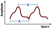
If a traveling wave has a fixed shape that repeats in space or in time, it is a periodic wave.[19] Such waves are sometimes regarded as having a wavelength even though they are not sinusoidal.[20] As shown in the figure, wavelength is measured between consecutive corresponding points on the waveform.
Wave packets
.gif)
Localized wave packets, "bursts" of wave action where each wave packet travels as a unit, find application in many fields of physics. A wave packet has an envelope that describes the overall amplitude of the wave; within the envelope, the distance between adjacent peaks or troughs is sometimes called a local wavelength.[21][22] An example is shown in the figure. In general, the envelope of the wave packet moves at a speed different from the constituent waves.[23]
Using Fourier analysis, wave packets can be analyzed into infinite sums (or integrals) of sinusoidal waves of different wavenumbers or wavelengths.[24]
Louis de Broglie postulated that all particles with a specific value of momentum p have a wavelength λ = h/p, where h is Planck's constant. This hypothesis was at the basis of quantum mechanics. Nowadays, this wavelength is called the de Broglie wavelength. For example, the electrons in a CRT display have a De Broglie wavelength of about 10−13 m. To prevent the wave function for such a particle being spread over all space, de Broglie proposed using wave packets to represent particles that are localized in space.[25] The spatial spread of the wave packet, and the spread of the wavenumbers of sinusoids that make up the packet, correspond to the uncertainties in the particle's position and momentum, the product of which is bounded by Heisenberg uncertainty principle.[24]
Interference and diffraction
Double-slit interference
When sinusoidal waveforms add, they may reinforce each other (constructive interference) or cancel each other (destructive interference) depending upon their relative phase. This phenomenon is used in the interferometer. A simple example is an experiment due to Young where light is passed through two slits.[26] As shown in the figure, light is passed through two slits and shines on a screen. The path of the light to a position on the screen is different for the two slits, and depends upon the angle θ the path makes with the screen. If we suppose the screen is far enough from the slits (that is, s is large compared to the slit separation d) then the paths are nearly parallel, and the path difference is simply d sin θ. Accordingly, the condition for constructive interference is:[27]
where m is an integer, and for destructive interference is:
Thus, if the wavelength of the light is known, the slit separation can be determined from the interference pattern or fringes, and vice versa.
For multiple slits, the pattern is [28]
where q is the number of slits, and g is the grating constant. The first factor, I1, is the single-slit result, which modulates the more rapidly varying second factor that depends upon the number of slits and their spacing. In the figure I1 has been set to unity, a very rough approximation.
The effect of interference is to redistribute the light, so the energy contained in the light is not altered, just where it shows up.[29]
Single-slit diffraction

The notion of path difference and constructive or destructive interference used above for the double-slit experiment applies as well to the display of a single slit of light intercepted on a screen. The main result of this interference is to spread out the light from the narrow slit into a broader image on the screen. This distribution of wave energy is called diffraction.
Two types of diffraction are distinguished, depending upon the separation between the source and the screen: Fraunhofer diffraction or far-field diffraction at large separations and Fresnel diffraction or near-field diffraction at close separations.
In the analysis of the single slit, the non-zero width of the slit is taken into account, and each point in the aperture is taken as the source of one contribution to the beam of light (Huygen's wavelets). On the screen, the light arriving from each position within the slit has a different path length, albeit possibly a very small difference. Consequently, interference occurs.
In the Fraunhofer diffraction pattern sufficiently far from a single slit, within a small-angle approximation, the intensity spread S is related to position x via a squared sinc function:[30]
- with
where L is the slit width, R is the distance of the pattern (on the screen) from the slit, and λ is the wavelength of light used. The function S has zeros where u is a non-zero integer, where are at x values at a separation proportion to wavelength.
Diffraction-limited resolution
Diffraction is the fundamental limitation on the resolving power of optical instruments, such as telescopes (including radiotelescopes) and microscopes.[31] For a circular aperture, the diffraction-limited image spot is known as an Airy disk; the distance x in the single-slit diffraction formula is replaced by radial distance r and the sine is replaced by 2J1, where J1 is a first order Bessel function.[32]
The resolvable spatial size of objects viewed through a microscope is limited according to the Rayleigh criterion, the radius to the first null of the Airy disk, to a size proportional to the wavelength of the light used, and depending on the numerical aperture:[33]
where the numerical aperture is defined as for θ being the half-angle of the cone of rays accepted by the microscope objective.
The angular size of the central bright portion (radius to first null of the Airy disk) of the image diffracted by a circular aperture, a measure most commonly used for telescopes and cameras, is:[34]
where λ is the wavelength of the waves that are focused for imaging, D the entrance pupil diameter of the imaging system, in the same units, and the angular resolution δ is in radians.
As with other diffraction patterns, the pattern scales in proportion to wavelength, so shorter wavelengths can lead to higher resolution.
Subwavelength
The term subwavelength is used to describe an object having one or more dimensions smaller than the length of the wave with which the object interacts. For example, the term subwavelength-diameter optical fibre means an optical fibre whose diameter is less than the wavelength of light propagating through it.
A subwavelength particle is a particle smaller than the wavelength of light with which it interacts (see Rayleigh scattering). Subwavelength apertures are holes smaller than the wavelength of light propagating through them. Such structures have applications in extraordinary optical transmission, and zero-mode waveguides, among other areas of photonics.
Subwavelength may also refer to a phenomenon involving subwavelength objects; for example, subwavelength imaging.
Angular wavelength
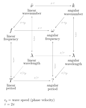
A quantity related to the wavelength is the angular wavelength (also known as reduced wavelength), usually symbolized by ƛ (lambda-bar). It is equal to the "regular" wavelength "reduced" by a factor of 2π (ƛ = λ/2π). It is usually encountered in quantum mechanics, where it is used in combination with the reduced Planck constant (symbol ħ, h-bar) and the angular frequency (symbol ω) or angular wavenumber (symbol k).
See also
- Emission spectrum
- Envelope (waves)
- Fraunhofer lines – dark lines in the solar spectrum, traditionally used as standard optical wavelength references
- Index of wave articles
- Length measurement
- Spectral line
- Spectroscopy
- Spectrum
References
- Hecht, Eugene (1987). Optics (2nd ed.). Addison Wesley. pp. 15–16. ISBN 0-201-11609-X.
- Brian Hilton Flowers (2000). "§21.2 Periodic functions". An introduction to numerical methods in C++ (2nd ed.). Cambridge University Press. p. 473. ISBN 0-19-850693-7.
- Raymond A. Serway; John W. Jewett (2006). Principles of physics (4th ed.). Cengage Learning. pp. 404, 440. ISBN 0-534-49143-X.
- A. A. Sonin (1995). The surface physics of liquid crystals. Taylor & Francis. p. 17. ISBN 2-88124-995-7.
- Keqian Zhang & Dejie Li (2007). Electromagnetic Theory for Microwaves and Optoelectronics. Springer. p. 533. ISBN 978-3-540-74295-1.
-
Theo Koupelis & Karl F. Kuhn (2007). In Quest of the Universe. Jones & Bartlett Publishers. p. 102. ISBN 0-7637-4387-9.
wavelength lambda light sound frequency wave speed.
- David C. Cassidy; Gerald James Holton; Floyd James Rutherford (2002). Understanding physics. Birkhäuser. pp. 339 ff. ISBN 0-387-98756-8.
- John Avison (1999). The World of Physics. Nelson Thornes. p. 460. ISBN 978-0-17-438733-6.
- To aid imagination, this bending of the wave often is compared to the analogy of a column of marching soldiers crossing from solid ground into mud. See, for example, Raymond T. Pierrehumbert (2010). Principles of Planetary Climate. Cambridge University Press. p. 327. ISBN 0-521-86556-5.
- Paul R Pinet (2009). op. cit. p. 242. ISBN 0-7637-5993-7.
- Bishwanath Chakraborty (2007). Principles of Plasma Mechanics. New Age International. p. 454. ISBN 978-81-224-1446-2.
- Jeffrey A. Hogan & Joseph D. Lakey (2005). Time-frequency and time-scale methods: adaptive decompositions, uncertainty principles, and sampling. Birkhäuser. p. 348. ISBN 978-0-8176-4276-1.
- See Figure 4.20 in A. Putnis (1992). Introduction to mineral sciences. Cambridge University Press. p. 97. ISBN 0-521-42947-1. and Figure 2.3 in Martin T. Dove (1993). Introduction to lattice dynamics (4th ed.). Cambridge University Press. p. 22. ISBN 0-521-39293-4.
- Manijeh Razeghi (2006). Fundamentals of solid state engineering (2nd ed.). Birkhäuser. pp. 165 ff. ISBN 0-387-28152-5.
- See Lord Rayleigh (1890). "Wave theory". Encyclopædia Britannica (9th ed.). The Henry G Allen Company. p. 422.
- Valery N. Pilipchuk (2010). "Figure 4.4: Transition from quasi-harmonic to cnoidal wave". Nonlinear Dynamics: Between Linear and Impact Limits. Springer. p. 127. ISBN 3642127983.
- Andrei Ludu (2012). "§18.3 Special functions". Nonlinear Waves and Solitons on Contours and Closed Surfaces (2nd ed.). Springer. pp. 469 ff. ISBN 3642228941.
- Alfred Osborne (2010). "Chapter 1: Brief history and overview of nonlinear water waves". Nonlinear Ocean Waves and the Inverse Scattering Transform. Academic Press. pp. 3 ff. ISBN 0-12-528629-5.
- Alexander McPherson (2009). "Waves and their properties". Introduction to Macromolecular Crystallography (2 ed.). Wiley. p. 77. ISBN 0-470-18590-2.
- Eric Stade (2011). Fourier Analysis. John Wiley & Sons. p. 1. ISBN 1-118-16551-9.
- Peter R. Holland (1995). The Quantum Theory of Motion: An Account of the de Broglie–Bohm Causal Interpretation of Quantum Mechanics. Cambridge University Press. p. 160. ISBN 978-0-521-48543-2.
-
Jeffery Cooper (1998). Introduction to partial differential equations with MATLAB. Springer. p. 272. ISBN 0-8176-3967-5.
The local wavelength λ of a dispersing wave is twice the distance between two successive zeros. ... the local wavelength and the local wave number k are related by k = 2π / λ.
- A. T. Fromhold (1991). "Wave packet solutions". Quantum Mechanics for Applied Physics and Engineering (Reprint of Academic Press 1981 ed.). Courier Dover Publications. pp. 59 ff. ISBN 0-486-66741-3.
(p. 61) ... the individual waves move more slowly than the packet and therefore pass back through the packet as it advances
- See, for example, Figs. 2.8–2.10 in Joy Manners (2000). "Heisenberg's uncertainty principle". Quantum Physics: An Introduction. CRC Press. pp. 53–56. ISBN 978-0-7503-0720-8.
- Ming Chiang Li (1980). "Electron Interference". In L. Marton; Claire Marton (eds.). Advances in Electronics and Electron Physics. 53. Academic Press. p. 271. ISBN 0-12-014653-3.
- Greenfield Sluder & David E. Wolf (2007). "IV. Young's Experiment: Two-Slit Interference". Digital microscopy (3rd ed.). Academic Press. p. 15. ISBN 0-12-374025-8.
- Halliday, Resnick, Walker (2008). "§35-4 Young's interference experiment". Fundamentals of Physics (Extended 8th ed.). Wiley-India. p. 965. ISBN 81-265-1442-6.CS1 maint: multiple names: authors list (link)
- Kordt Griepenkerl (2002). "§9.8.2 Diffraction by a grating". In John W Harris; Walter Benenson; Horst Stöcker; Holger Lutz (eds.). Handbook of physics. Springer. pp. 307 ff. ISBN 0-387-95269-1.
- Douglas B. Murphy (2002). Fundamentals of light microscopy and electronic imaging. Wiley/IEEE. p. 64. ISBN 0-471-23429-X.
- John C. Stover (1995). Optical scattering: measurement and analysis (2nd ed.). SPIE Press. p. 64. ISBN 978-0-8194-1934-7.
- Graham Saxby (2002). "Diffraction limitation". The science of imaging. CRC Press. p. 57. ISBN 0-7503-0734-X.
- Grant R. Fowles (1989). Introduction to Modern Optics. Courier Dover Publications. pp. 117–120. ISBN 978-0-486-65957-2.
- James B. Pawley (1995). Handbook of biological confocal microscopy (2nd ed.). Springer. p. 112. ISBN 978-0-306-44826-3.
- Ray N. Wilson (2004). Reflecting Telescope Optics I: Basic Design Theory and Its Historical Development. Springer. p. 302. ISBN 978-3-540-40106-3.
External links
| Wikimedia Commons has media related to Wavelength. |
