Radiant heating and cooling
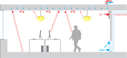
Radiant heating and cooling is a category of HVAC technologies that exchange heat by both convection and radiation with the environments they are designed to heat or cool. There are many subcategories of radiant heating and cooling, including: "radiant ceiling panels"[1], "embedded surface systems"[1], "thermally active building systems"[1], and infrared heaters. According to some definitions, a technology is only included in this category if radiation comprises more than 50% of its heat exchange with the environment[2]; therefore technologies such as radiators and chilled beams (which may also involve radiation heat transfer) are usually not considered radiant heating or cooling. Within this category, it is practical to distinguish between high temperature radiant heating (devices with emitting source temperature >≈300 °F), and radiant heating or cooling with more moderate source temperatures. This article mainly addresses radiant heating and cooling with moderate source temperatures, used to heat or cool indoor environments. Moderate temperature radiant heating and cooling is usually composed of relatively large surfaces that are internally heated or cooled using hydronic or electrical sources. For high temperature indoor or outdoor radiant heating, see: Infrared heater. For snow melt applications see: Snowmelt system.
Heating
.jpg)
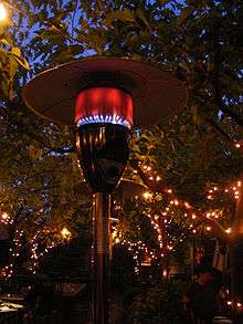
Radiant heating is a technology for heating indoor and outdoor areas. Heating by radiant energy is observed every day, the warmth of the sunshine being the most commonly observed example. Radiant heating as a technology is more narrowly defined. It is the method of intentionally using the principles of radiant heat to transfer radiant energy from an emitting heat source to an object. Designs with radiant heating are seen as replacements for conventional convection heating as well as a way of supplying confined outdoor heating.
Indoor
Radiant heating heats a building through radiant heat, rather than conventional methods such as radiators (mostly convection heating). An example is the Austrian/German cocklestove (Kachelofen), a type of masonry heater. Mixed radiation, convection and conduction systems have existed since the Roman use of hypocaust heating.[3] Underfloor radiant heating has long been widespread in China and South Korea.[4] The heat energy is emitted from a warm element, such as a floor, wall or overhead panel, and warms people and other objects in rooms rather than directly heating the air. The internal air temperature for radiant heated buildings may be lower than for a conventionally heated building to achieve the same level of body comfort, when adjusted so the perceived temperature is actually the same. One of the key advantages of radiant heating systems is a much decreased circulation of air inside the room and the corresponding spreading of airborne particles.
Radiant heating/cooling systems can be divided into:
- Underfloor heating systems—electric or hydronic
- Wall heating systems
- Radiant ceiling panels
Underfloor and wall heating systems often are called low-temperature systems. Since their heating surface is much larger than other systems, a much lower temperature is required to achieve the same level of heat transfer. This provides an improved room climate with healthier humidity levels. The maximum temperature of the heating surface can vary from 29–35 °C (84–95 °F) depending on the room type. Radiant overhead panels are mostly used in production and warehousing facilities or sports centers; they hang a few meters above the floor and their surface temperatures are much higher.
Outdoors
In the case of heating outdoor areas, the surrounding air is constantly moving. Relying on convection heating is in most cases impractical, the reason being that, once you heat the outside air, it will blow away with air movement. Even in a no-wind condition, the buoyancy effects will carry away the hot air. Outdoor radiant heaters allow specific spaces within an outdoor area to be targeted, warming only the people and objects in their path. Radiant heating systems may be gas-fired or use electric infrared heating elements. An example of the overhead radiant heaters are the patio heaters often used with outdoor serving. The top metal disc reflects the radiant heat onto a small area.
Cooling
Radiant cooling is the use of cooled surfaces to remove sensible heat primarily by thermal radiation and only secondarily by other methods like convection. ASHRAE defines radiant systems as temperature-controlled surfaces where 50% or more of the design heat transfer takes place by thermal radiation.[5] Radiant systems that use water to cool the radiant surfaces examples of hydronic systems. Unlike “all-air” air conditioning systems that circulate cooled air only, hydronic radiant systems circulate cooled water in pipes through specially-mounted panels on a building's floor or ceiling to provide comfortable temperatures. There is a separate system to provide air for ventilation, dehumidification, and potentially additionally cooling.[5] Radiant systems are less common than all-air systems for cooling, but can have advantages compared to all-air systems in some applications.[6][7][8]
Since the majority of the cooling process results from removing sensible heat through radiant exchange with people and objects and not air, occupant thermal comfort can be achieved with warmer interior air temperatures than with air based cooling systems. Radiant cooling systems potentially offer reductions in cooling energy consumption.[6] The latent loads (humidity) from occupants, infiltration and processes generally need to be managed by an independent system. Radiant cooling may also be integrated with other energy-efficient strategies such as night time flushing, indirect evaporative cooling, or ground source heat pumps as it requires a small difference in temperature between desired indoor air temperature and the cooled surface.[9]
Fluorescent radiant cooling uses a coating that fluoresces in the infrared atmospheric window, a frequency range where the atmosphere is unusually transparent, so that the energy goes straight out to space. This can cool the heat-fluorescent object to below ambient air temperature, even in full sun.[10][11][12]
History
Early radiant cooling systems were installed in the late 1930s and 1940s in Europe[13] and by the 1950s in the US.[14] They became more common in Europe in the 1990s and continue to be used today.[15]
Advantages
Radiant cooling systems offer lower energy consumption than conventional cooling systems based on research conducted by the Lawrence Berkeley National Laboratory. Radiant cooling energy savings depend on the climate, but on average across the US savings are in the range of 30% compared to conventional systems. Cool, humid regions might have savings of 17% while hot, arid regions have savings of 42%.[6] Hot, dry climates offer the greatest advantage for radiant cooling as they have the largest proportion of cooling by way of removing sensible heat. While this research is informative, more research needs to be done to account for the limitations of simulation tools and integrated system approaches. Much of the energy savings is also attributed to the lower amount of energy required to pump water as opposed to distribute air with fans. By coupling the system with building mass, radiant cooling can shift some cooling to off-peak night time hours. Radiant cooling appears to have lower first costs[16] and lifecycle costs compared to conventional systems. Lower first costs are largely attributed to integration with structure and design elements, while lower life cycle costs result from decreased maintenance. However, a recent study on comparison of VAV reheat versus active chilled beams & DOAS challenged the claims of lower first cost due to added cost of piping[17]
Limiting factors
Because of the potential for condensate formation on the cold radiant surface (resulting in water damage, mold and the like), radiant cooling systems have not been widely applied. Condensation caused by humidity is a limiting factor for the cooling capacity of a radiant cooling system. The surface temperature should not be equal or below the dew point temperature in the space. Some standards suggest a limit for the relative humidity in a space to 60% or 70%. An air temperature of 26 °C (79 °F) would mean a dew point between 17 °C and 20 °C (63 °F and 68 °F).[9] There is, however, evidence that suggests decreasing the surface temperature to below the dew point temperature for a short period of time may not cause condensation.[16] Also, the use of an additional system, such as a dehumidifier or DOAS, can limit humidity and allow for increased cooling capacity.
System description
While there are a broad range of system technologies, there are two primary types of radiant cooling systems. The first type is systems that deliver cooling through the building structure, usually slabs. These systems are also named thermally activated building systems (TABS).[18] The second type is systems that deliver cooling through specialized panels. Systems using concrete slabs are generally cheaper than panel systems and offer the advantage of thermal mass, while panel systems offer faster temperature control and flexibility.
Chilled slabs
Radiant cooling from a slab can be delivered to a space from the floor or ceiling. Since radiant heating systems tend to be in the floor, the obvious choice would be to use the same circulation system for cooled water. While this makes sense in some cases, delivering cooling from the ceiling has several advantages.
First, it is easier to leave ceilings exposed to a room than floors, increasing the effectiveness of thermal mass. Floors offer the downside of coverings and furnishings that decrease the effectiveness of the system.
Second, greater convective heat exchange occurs through a chilled ceiling as warm air rises, leading to more air coming in contact with the cooled surface.
Cooling delivered through the floor makes the most sense when there is a high amount of solar gain from sun penetration, because the cool floor can more easily remove those loads than the ceiling.[9]
Chilled slabs, compared to panels, offer more significant thermal mass and therefore can take better advantage of outside diurnal temperatures swings. Chilled slabs cost less per unit of surface area, and are more integrated with structure.
Chilled beam/ceiling
Radiant/convective heating/cooling systems are generally integrated into slab or dropped ceilings, or attached to ceilings, but can be attached to walls also. The modular nature of ceiling panels offers increased flexibility in terms of placement and integration with lighting or other electrical systems, but are less efficient than chilled beam systems. Lower thermal mass compared to chilled slabs means they can't easily take advantage of passive cooling from thermal storage, but controls can more quickly adjust to changes in outdoor temperature. Chilled beams/ceilings are also better suited to buildings with spaces that have a greater variance in cooling loads.[5] Perforated panels also offer better acoustical dampening than chilled slabs. Ceiling panels are very suitable for retrofits because they can be attached to any ceiling. Chilled ceiling panels can be more easily integrated with ventilation supplied from the ceiling.
Thermal comfort
The operative temperature is an indicator of thermal comfort which takes into account the effects of both convection and radiation. Operative temperature is defined as a uniform temperature of a radiantly black enclosure in which an occupant would exchange the same amount of heat by radiation plus convection as in the actual nonuniform environment.
With radiant systems, thermal comfort is achieved at warmer interior temp than all-air systems for cooling scenario, and at lower temperature than all-air systems for heating scenario.[19] Thus, radiant systems can helps to achieve energy savings in building operation while maintaining the wished comfort level.
Thermal comfort in radiant vs. all-air buildings
Based on a large study performed using Center for the Built Environment's Indoor environmental quality (IEQ) occupant survey to compare occupant satisfaction in radiant and all-air conditioned buildings, both systems create equal indoor environmental conditions, including acoustic satisfaction, with a tendency towards improved temperature satisfaction in radiant buildings.[20]
Radiant temperature asymmetry
The radiant temperature asymmetry is defined as the difference between the plane radiant temperature of the two opposite sides of a small plane element. As regards occupants within a building, thermal radiation field around the body may be non-uniform due to hot and cold surfaces and direct sunlight, bringing therefore local discomfort. The norm ISO 7730 and the ASHRAE 55 standard give the predicted percentage of dissatisfied occupants (PPD) as a function of the radiant temperature asymmetry and specify the acceptable limits. In general, people are more sensitive to asymmetric radiation caused by a warm ceiling than that caused by hot and cold vertical surfaces. The detailed calculation method of percentage dissatisfied due to a radiant temperature asymmetry is described in ISO 7730.
Design considerations
While specific design requirements will depend on the type of radiant system, a few issues are common to most radiant systems.
- For cooling application, radiant systems can lead condensation issues. Local climate needs to be evaluated and taken into account in the design. Air dehumidification can be necessary for humid climate.
- Many types of radiant systems incorporate massive building elements. The thermal mass involved will have a consequence on the thermal response of the system. The operation schedule of a space and the control strategy of the radiant system play a key role in the proper functioning of the system.
- Many types of radiant systems incorporate hard surfaces which influence indoor acoustics. Additional acoustic solutions may need to be considered.
- A design strategy to reduce acoustical impacts of radiant systems is using free-hanging acoustical clouds. Cooling experiments on free-hanging acoustical clouds for an office room showed that for 47% cloud coverage of the ceiling area, 11% reduction in cooling capacity was caused by the cloud coverage. Good acoustic quality can be achieved with only minor reduction of cooling capacity.[21] Combining acoustical clouds and ceiling fans can offset the modest reduction in cooling capacity from a radiant cooled ceiling caused by the presence of the clouds, and results in increase in cooling capacity.[21][22]
Hydronic radiant systems
Radiant cooling systems are usually hydronic, cooling using circulating water running in pipes in thermal contact with the surface. Typically the circulating water only needs to be 2–4 °C below the desired indoor air temperature.[9] Once having been absorbed by the actively cooled surface, heat is removed by water flowing through a hydronic circuit, replacing the warmed water with cooler water.
Depending on the position of the pipes in the building construction, hydronic radiant systems can be sorted into 4 main categories:
- Embedded Surface Systems: pipes embedded within the surface layer (not within the structure)
- Thermally Active Building Systems (TABS): the pipes thermally coupled and embedded in the building structure (slabs, walls)[23]
- Capillary Surface Systems: pipes embedded in a layer at the inner ceiling/wall surface
- Radiant Panels: metal pipes integrated into panels (not within the structure); heat carrier close to the surface
Types (ISO 11855)
The norm ISO 11855-2[24] focuses on embedded water based surface heating and cooling systems and TABS. Depending on construction details, this norm distinguishes 7 different types of those systems (Types A to G)
- Type A with pipes embedded in the screed or concrete (“wet” system)
- Type B with pipes embedded outside the screed (in the thermal insulation layer, “dry” system)
- Type C with pipes embedded in the leveling layer, above which the second screed layer is placed
- Type D include plane section systems (extruded plastic / group of capillary grids)
- Type E with pipes embedded in a massive concrete layer
- Type F with capillary pipes embedded in a layer at the inner ceiling or as a separate layer in gypsum
- Type G with pipes embedded in a wooden floor construction
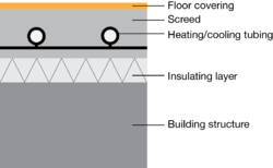 Section diagram of a radiant embedded surface system (ISO 11855, type A) |
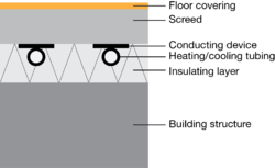 Section diagram of a radiant embedded surface system (ISO 11855, type B) |
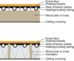 Section diagram of a radiant embedded surface system (ISO 11855, type G) |
 Section diagram of thermally activated building system (ISO 11855, type E) |
 Section diagram of radiant capillary system (ISO 11855, type F) |
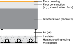 Section diagram of a radiant panel |
Energy sources
Radiant systems are associated with low-exergy systems. Low-exergy refers to the possibility to utilize ‘low quality energy’ (i.e. dispersed energy that has little ability to do useful work). Both heating and cooling can in principle be obtained at temperature levels that are close to the ambient environment. The low temperature difference requires that the heat transmission takes place over relative big surfaces as for example applied in ceilings or underfloor heating systems.[25] Radiant systems using low temperature heating and high temperature cooling are typical example of low-exergy systems. Energy sources such as geothermal (direct cooling / geothermal heat pump heating) and solar hot water are compatible with radiant systems. These sources can lead to important savings in terms of primary energy use for buildings.
Commercial buildings using radiant cooling
Some well-known buildings using radiant cooling include Bangkok's Suvarnabhumi Airport,[26] the Infosys Software Development Building 1 in Hyderabad, IIT Hyderabad,[27] and the San Francisco Exploratorium[28]. Radiant cooling is also used in many zero net energy buildings.[29][30]
| Building | Year | Country | City | Architect | Radiant system design | Radiant system category |
|---|---|---|---|---|---|---|
| Kunsthaus Bregenz | 1997 | Austria | Bregenz | Peter Zumthor | Meierhans+Partner | Thermally activated building systems |
| Suvarnabhumi Airport | 2005 | Thailand | Bangkok | Murphy Jahn | Transsolar and IBE | Embedded surface systems |
| Zollverein School | 2006 | Germany | Essen | SANAA | Transsolar | Thermally activated building systems |
| Klarchek Information Commons, Loyola University Chicago | 2007 | United States | Chicago, IL | Solomon Cordwell Buenz | Transsolar | Thermally activated building systems |
| Lavin-Bernick Center, Tulane University | 2007 | United States | New Orleans, LA | VAJJ | Transsolar | Radiant panels |
| David Brower Center | 2009 | United States | Berkeley, CA | Daniel Solomon Design Partners | Integral Group | Thermally activated building systems |
| Manitoba Hydro | 2009 | Canada | Winnipeg, MB | KPMB Architects | Transsolar | Thermally activated building systems |
| Cooper Union | 2009 | United States | New York, NY | Morphosis Architects | IBE / Syska Hennessy Group | Radiant panels |
| Exploratorium (Pier 15-17) | 2013 | United States | San Francisco, CA | EHDD | Integral Group | Embedded surface systems |
| Federal Center South | 2012 | United States | Seattle, WA | ZGF Architects | WSP Flack+Kurtz | Radiant Panels |
| Bertschi School Living Science Building Wing | 2010 | United States | Seattle, WA | KMD Architects | Rushing | Thermally activated building systems |
| UW Molecular Engineering Building | 2012 | United States | Seattle, WA | ZGF Architects | Affiliated Engineers | Embedded surface systems |
| First Hill Streetcar Operations | 2014 | United States | Seattle, WA | Waterleaf Architecture | LTK Engineering | Thermally activated building systems |
| Bullitt Center | 2013 | United States | Seattle, WA | Miller Hull Partnership | PAE Engineering | Embedded surface systems |
| John Prairie Operations Center | 2011 | United States | Shelton, WA | TCF Architecture | Interface | Embedded surface systems |
| University of Florida Lake Nona Research Center | 2012 | United States | Orlando, FL | HOK | Affiliated Engineers | Radiant Panels |
| William Jefferson Clinton Presidential Library | 2004 | United States | Little Rock, AR | Polshek Partnership | WSP Flack+Kurtz / Cromwell | Thermally activated building systems |
| Hunter Museum of Art | 2006 | United States | Chattanooga, TN | Randall Stout | IBE | Embedded surface systems |
| HOK St Louis Office | 2015 | United States | St. Louis, MO | HOK | HOK | Radiant panels |
| Carbon Neutral Energy Solutions Laboratory, Georgia Tech | 2012 | United States | Atlanta, GA | HDR Architecture | HDR Architecture | Thermally activated building systems |
Physics
Heat radiation is the energy in the form of electromagnetic waves emitted by a solid, liquid, or gas as a result of its temperature.[31] In buildings, the radiant heat flow between two internal surfaces (or a surface and a person) is influenced by the emissivity of the heat emitting surface and by the view factor between this surface and the receptive surface (object or person) in the room.[32] Thermal (longwave) radiation travels at the speed of light, in straight lines.[5] It can be reflected. People, equipment, and surfaces in buildings will warm up if they absorb thermal radiation, but the radiation does not noticeably heat up the air it is traveling through.[5] This means heat will flow from objects, occupants, equipment, and lights in a space to a cooled surface as long as their temperatures are warmer than that of the cooled surface and they are within the direct or indirect line of sight of the cooled surface. Some heat is also removed by convection because the air temperature will be lowered when air comes in contact with the cooled surface.
The heat transfer by radiation is proportional to the power of four of the absolute surface temperature.
The emissivity of a material (usually written ε or e) is the relative ability of its surface to emit energy by radiation. A black body has an emissivity of 1 and a perfect reflector has an emissivity of 0.[31]
In radiative heat transfer, a view factor quantifies the relative importance of the radiation that leaves an object (person or surface) and strikes another one, considering the other surrounding objects. In enclosures, radiation leaving a surface is conserved, therefore, the sum of all view factors associated with a given object is equal to 1. In the case of a room, the view factor of a radiant surface and a person depend on their relative positions. As a person is often changing position and as a room might be occupied by many persons at the same time, diagrams for omnidirectional person can be used.[33]
Thermal response time
Response time (τ95), aka time constant, is used to analyze the dynamic thermal performance of radiant systems. The response time for a radiant system is defined as the time it takes for the surface temperature of a radiant system to reach 95% of the difference between its final and initial values when a step change in control of the system is applied as input.[34] It is mainly influenced by concrete thickness, pipe spacing, and to a less degree, concrete type. It is not affected by pipe diameter, room operative temperature, supply water temperature, and water flow regime. By using response time, radiant systems can be classified into fast response (τ95< 10 min, like RCP), medium response (1 h<τ95<9 h, like Type A, B, D, G) and slow response (9 h< τ95<19 h, like Type E and Type F).[34] Additionally, floor and ceiling radiant systems have different response times due to different heat transfer coefficients with room thermal environment, and the pipe-embedded position.
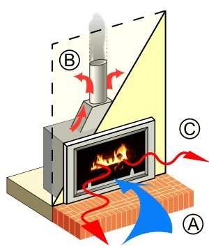
Other HVAC systems that exchange heat by radiation
Fireplaces and woodstoves
See also
- Glossary of HVAC
References
- ISO. (2012). ISO 11855:2012—Building environment design-Design, dimensioning, installation and control of embedded radiant heating and cooling systems. International Organization for Standardization.
- ASHRAE Handbook. HVAC Systems and Equipment. Chapter 6. Panel Heating and Cooling, American Society of Heating and Cooling, 2012
- History of Radiant Heating & Cooling Systems - Part 2, By Robert Bean, Bjarne W. Olesen, Kwang Woo Kim. ASHRAE Journal, vol. 52, no. 2, February 2010
- Bean, Robert; Olesen, Bjarne; Kim, Kwang Woo (February 2010). "History of Radiant Heating and Cooling Systems – Part 2" (PDF). ASHRAE Journal. Atlanta, GA (USA): ASHRAE. Retrieved November 8, 2017.
- ASHRAE Handbook. HVAC Systems and Equipment. Chapter 6. Panel Heating and Cooling Design. ASHRAE. 2016.
- Stetiu, Corina (June 1999). "Energy and peak power savings potential of radiant cooling systems in US commercial buildings" (PDF). Energy and Buildings. 30 (2): 127–138. doi:10.1016/S0378-7788(98)00080-2.
- Higgins C, Carbonnier K (June 2017). Energy Performance of Commercial Buildings with Radiant Heating and Cooling (Report). pp. 9–12. Retrieved November 8, 2017.
- Karmann, Caroline; Schiavon, Stefano; Bauman, Fred (January 2017). "Thermal comfort in buildings using radiant vs. all-air systems: A critical literature review". Building and Environment. 111: 123–131. doi:10.1016/j.buildenv.2016.10.020.
- Olesen, Bjarne W. (September 2008). "Hydronic Floor Cooling Systems". ASHRAE Journal.
- Raman, Aaswath P.; Anoma, Marc Abou; Zhu, Linxiao; Rephaeli, Eden; Fan, Shanhui (November 2014). "Passive radiative cooling below ambient air temperature under direct sunlight". Nature. 515 (7528): 540–544. Bibcode:2014Natur.515..540R. doi:10.1038/nature13883. ISSN 1476-4687. PMID 25428501.
- Burnett, Michael (November 25, 2015). "Passive Radiative Cooling". large.stanford.edu.
- Berdahl, Paul; Chen, Sharon S.; Destaillats, Hugo; Kirchstetter, Thomas W.; Levinson, Ronnen M.; Zalich, Michael A. (December 2016). "Fluorescent cooling of objects exposed to sunlight – The ruby example". Solar Energy Materials and Solar Cells. 157: 312–317. doi:10.1016/j.solmat.2016.05.058.
- Giesecke, Frederick E. (1947). "Chapter 24 - Radiant cooling". Hot-water heating and radiant heating and radiant cooling. Austin, Texas: Technical Book Company.
24-6. The first large building in Zurich equipped with a combination radiant heating and cooling system is the department store Jelmoli (Fig 24-1). The first sections of this store were erected during the period from 1899 to 1932 and equipped with a standard radiator-heating system using low-pressure steam; the latest section was erected in 1933-37 and equipped with a combination radiant heating and cooling system...The Administration Building of Saurer Co. in Arbon and the Municipal Hospital in Basel are among the more important buildings recently equipped with radiant cooling systems.
- Manley, John K., ed. (1954). "Radiant cooling and air conditioning". Radiant Heating, Radiant Cooling. Bulletin No. 1. Pratt Institute School of Architecture. pp. 24–25. OCLC 11520430.
This type of system has proved successful in several installations. It was first attempted in a few sample rooms in Radio City about five years ago. Since that time, it has appeared in the 30-storey Alcoa Building as well as in another multi-story building in Canada. Both of the latter structures are heated in winter and cooled in summer by the same coils of pipe in metal ceilings.
- Olesen, Bjarne W. (February 2012). "Thermo Active Building Systems Using Building Mass to Heat and Cool" (PDF). ASHRAE Journal. Vol. 54 no. 2. Atlanta, GA (USA): ASHRAE. Retrieved November 20, 2017.
- Mumma, S.A. (2002). "Chilled ceilings in parallel with dedicated outdoor air systems: Addressing the concerns of condensation, capacity, and cost". ASHRAE Transactions. 108 (2): 220–231.
- Stein, Jeff; Steven T. Taylor (2013). "VAV Reheat Versus Active Chilled Beams & DOAS". ASHRAE Journal. 55 (5): 18–32.
- Gwerder, M.; B. Lehmann; J. Tödtli; V. Dorer; F. Renggli (July 2008). "Control of thermally-activated building systems (TABS)". Applied Energy. 85 (7): 565–581. doi:10.1016/j.apenergy.2007.08.001.
- ISO 11855-1. Building Environment Design - Design, Construction and Operation of Radiant Heating and Cooling Systems - Part 1, ISO, 2012
- Karmann, Caroline; Schiavon, Stefano; Graham, Lindsay T.; Raftery, Paul; Bauman, Fred (December 2017). "Comparing temperature and acoustic satisfaction in 60 radiant and all-air buildings". Building and Environment. 126: 431–441. doi:10.1016/j.buildenv.2017.10.024. ISSN 0360-1323.
- Karmann, Caroline; Bauman, Fred S.; Raftery, Paul; Schiavon, Stefano; Frantz, William H.; Roy, Kenneth P. (March 2017). "Cooling capacity and acoustic performance of radiant slab systems with free-hanging acoustical clouds". Energy and Buildings. 138: 676–686. doi:10.1016/j.enbuild.2017.01.002. ISSN 0378-7788.
- Karmann, Caroline; Bauman, Fred; Raftery, Paul; Schiavon, Stefano; Koupriyanov, Mike (January 2018). "Effect of acoustical clouds coverage and air movement on radiant chilled ceiling cooling capacity". Energy and Buildings. 158: 939–949. doi:10.1016/j.enbuild.2017.10.046. ISSN 0378-7788.
- Babiak, Jan; Olesen, Bjarne W.; Petras, Dusan (2007), Low temperature heating and high temperature cooling: REHVA GUIDEBOOK No 7, REHVA
- ISO 11855-2. Building Environment Design - Design, Construction and Operation of Radiant Heating and Cooling Systems - Part 2, ISO, 2012
- Nielsen, Lars Sønderby (2012), "Building Integrated System Design for Sustainable Heating and Cooling" (PDF), REHVA Journal: 24–27
- Simmonds, P.; Holst, S.; Reuss, S.; Gaw, W. (June 1, 2000). "Using Radiant Cooled Floors to Condition Large Spaces and Maintain Comfort Conditions". ASHRAE Transactions: Symposia. ASHRAE Winter Meeting. Dallas, TX (US): American Society of Heating, Refrigerating and Air-Conditioning Engineers. pp. 695–701. CiteSeerX 10.1.1.258.6616. OSTI 20104826.
- Sastry, Guruprakash; Rumsey, Peter (May 2014). "VAV vs. Radiant - side by side comparison". ASHRAE Journal. Atlanta, GA (USA): ASHRAE. Archived from the original on 9 November 2017. Retrieved 8 November 2017.
- Wenisch, Joseph; Gaunt, Lindsey (Spring 2015). "Inspiring explorers - Case study: The Exploratorium" (PDF). High Performing Buildings. Atlanta, GA (USA): ASHRAE. eISSN 1940-3054. Retrieved November 8, 2017.
- 2016 List of Zero Net Energy Buildings (Report). New Buildings Institute. October 13, 2016. p. 8. Retrieved November 8, 2017.
- Maor, Itzhak; Snyder, Steven C. (Fall 2016). "Evaluation of Factors Impacting EUI from High Performing Building Case Studies". High Performing Buildings. Atlanta, GA (USA): ASHRAE. eISSN 1940-3054. Retrieved November 8, 2017.
- Oxford Reference, Oxford University
- Babiak, Jan (2007), PhD Thesis, Low Temperature Heating and High Temperature Cooling. Thermally activated building system, Department of Building Services, Technical University of Denmark
- ISO, EN. 7726. Ergonomics of the thermal environments-Instruments for measuring physical quantities, ISO, Geneva, International Organisation for Standardisation, 1998
- Ning, Baisong; Schiavon, Stefano; Bauman, Fred S. (2017). "A novel classification scheme for design and control of radiant system based on thermal response time". Energy and Buildings. 137: 38–45. doi:10.1016/j.enbuild.2016.12.013. ISSN 0378-7788.
Further reading
- ASHRAE Handbook. HVAC Systems and Equipment 2012. Chapter 13. Hydronic Heating and Cooling.
- Kessling, W., Holst, S., Schuler, M. Innovative Design Concept for the New Bangkok International Airport, NBIA.
- Olesen, B.W. Radiant Heating and Cooling by Water-based systems. Technical University of Denmark, International Centre for Indoor Environment and Energy.
External links
- Radiant cooling research at the Center for the Built Environment
- Center for the Built Environment's Occupant Indoor Environmental Quality (IEQ) Survey
- US Dept of Energy Guide to Radiant Heating
- Infrared Heater Safety Council
- Radiant Panel Association
- Map of buildings using hydronic radiant heating and cooling systems