Parallel projection
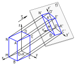
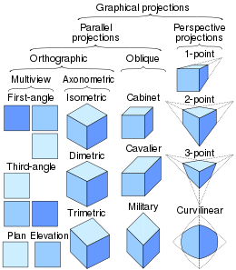
A parallel projection is a projection of an object in three-dimensional space onto a fixed plane, known as the projection plane or image plane, where the rays, known as lines of sight or projection lines, are parallel to each other. It is a basic tool in descriptive geometry. The projection is called orthographic if the rays are perpendicular (orthogonal) to the image plane, and oblique or skew if they are not.
| Part of a series on |
| Graphical projection |
|---|
 |
|
Views
|
|
Topics
|
Overview
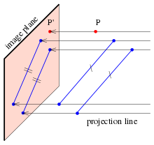
A parallel projection is a particular case of projection in mathematics and graphical projection in technical drawing. Parallel projections can be seen as the limit of a central or perspective projection, in which the rays pass through a fixed point called the center or viewpoint, as this point is moved towards infinity. Put differently, a parallel projection corresponds to a perspective projection with an infinite focal length (the distance between the lens and the focal point in photography) or "zoom". In parallel projections, lines that are parallel in three-dimensional space remain parallel in the two-dimensional projected image.
A perspective projection of an object is often considered more realistic than a parallel projection, since it more closely resembles human vision and photography. However, parallel projections are popular in technical applications, since the parallelism of an object's lines and faces is preserved, and direct measurements can be taken from the image. Among parallel projections, orthographic projections are the most realistic, and are commonly used by engineers. On the other hand, certain types of oblique projections (for example cavalier projection, military projection) are very simple to implement, and are used to create quick and informal pictorials of objects.
The term parallel projection is used in the literature to describe both the procedure itself (a mathematical mapping function) as well as the resulting image produced by the procedure.
Properties
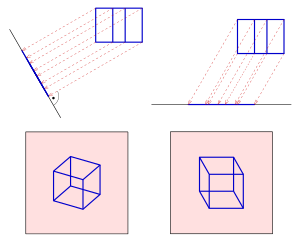
Every parallel projection has the following properties.
- It is uniquely defined by its projection plane Π and the direction of the (parallel) projection lines. The direction must not be parallel to the projection plane.
- Any point of the space has a unique image in the projection plane Π, and the points of Π are fixed.
- Any line not parallel to direction is mapped onto a line; any line parallel to is mapped onto a point.
- Parallel lines are mapped on parallel lines, or on a pair of points (if they are parallel to ).
- The ratio of the length of two line segments on a line stays unchanged. As a special case, midpoints are mapped on midpoints.
- The length of a line segment parallel to the projection plane remains unchanged. The length of any line segment is shortened if the projection is an orthographic one.
- Any circle that lies in a plane parallel to the projection plane is mapped onto a circle with the same radius. Any other circle is mapped onto an ellipse or a line segment (if direction is parallel to the circle's plane).
- Angles in general are not preserved. But right angles with one line parallel to the projection plane remain unchanged.
- Any rectangle is mapped onto a parallelogram or a line segment (if is parallel to the rectangle's plane).
- Any figure in a plane that is parallel to the image plane is congruent to its image.
Orthographic projection


Orthographic projection is derived from the principles of descriptive geometry, and is a type of parallel projection where the projection rays are perpendicular to the projection plane. It is the projection type of choice for working drawings.
The term orthographic is sometimes reserved specifically for depictions of objects where the principal axes or planes of the object are parallel with the projection plane (or the paper on which the orthographic or parallel projection is drawn). However, the term multiview projection is also used. In multiview projections, up to six pictures of an object are produced, with each projection plane perpendicular to one of the coordinate axes. Sub-types of multiview orthographic projections include plans, elevations and sections.
When the principal planes or axes of an object are not parallel with the projection plane, but are rather tilted to some degree to reveal multiple sides of the object, it is called an axonometric projection.[1] Axonometric projection (not to be confused with the closely related principle of axonometry, as described in Pohlke's theorem) is further subdivided into three groups: isometric, dimetric and trimetric projection, depending on the exact angle at which the view deviates from the orthogonal.[2][3] A typical (but not obligatory) characteristic of axonometric pictorials is that one axis of space is usually displayed as vertical.
Oblique projection
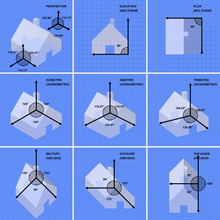
In an oblique projection, the parallel projection rays are not perpendicular to the viewing plane, but strike the projection plane at an angle other than ninety degrees.[2] In both orthographic and oblique projection, parallel lines in space appear parallel on the projected image. Because of its simplicity, oblique projection is used exclusively for pictorial purposes rather than for formal, working drawings. In an oblique pictorial drawing, the displayed angles among the axes as well as the foreshortening factors (scale) are arbitrary. The distortion created thereby is usually attenuated by aligning one plane of the imaged object to be parallel with the plane of projection thereby creating a true shape, full-size image of the chosen plane. Special types of oblique projections include military, cavalier and cabinet projection.[4]
Analytic representation
If the image plane is given by equation and the direction of projection by , then the projection line through the point is parametrized by
- with .
The image of is the intersection of line with plane ; it is given by the equation
In several cases, these formulas can be simplified.
(S1) If one can choose the vectors and such that , the formula for the image simplifies to
(S2) In an orthographic projection, the vectors and are parallel. In this case, one can choose and one gets
(S3) If one can choose the vectors and such that , and if the image plane contains the origin, one has and the parallel projection is a linear mapping:
(Here is the identity matrix and the outer product.)
From this analytic representation of a parallel projection one can deduce most of the properties stated in the previous sections.
See also
References
- Schaum's Outline: Descriptive Geometry, McGraw-Hill, (June 1, 1962),ISBN 978-0070272903
- Joseph Malkevitch (April 2003), "Mathematics and Art", Feature Column Archive, American Mathematical Society
- Ingrid Carlbom, Joseph Paciorek (December 1978), "Planar Geometric Projections and Viewing Transformations", ACM Computing Surveys, 10 (4): 465–502, doi:10.1145/356744.356750
- Mitchell, William; Malcolm McCullough (1994). Digital design media. John Wiley and Sons. p. 169. ISBN 0-471-28666-4.
- Maynard, Patric (2005). Drawing distinctions: the varieties of graphic expression. Cornell University Press. p. 22. ISBN 0-8014-7280-6.
- McReynolds, Tom; David Blythe (2005). Advanced graphics programming using openGL. Elsevier. p. 502. ISBN 1-55860-659-9.
- Desai, Apurva A. Computer Graphics. PHI Learning Pvt. Ltd. p. 242. ISBN 81-203-3524-4.