Balance wheel
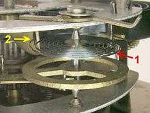
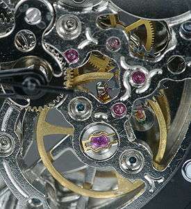
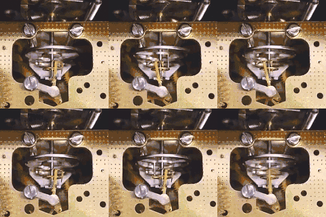
A balance wheel, or balance, is the timekeeping device used in mechanical watches and some clocks, analogous to the pendulum in a pendulum clock. It is a weighted wheel that rotates back and forth, being returned toward its center position by a spiral torsion spring, the balance spring or hairspring. It is driven by the escapement, which transforms the rotating motion of the watch gear train into impulses delivered to the balance wheel. Each swing of the wheel (called a 'tick' or 'beat') allows the gear train to advance a set amount, moving the hands forward. The balance wheel and hairspring together form a harmonic oscillator, which due to resonance oscillates preferentially at a certain rate, its resonant frequency or 'beat', and resists oscillating at other rates. The combination of the mass of the balance wheel and the elasticity of the spring keep the time between each oscillation or ‘tick’ very constant, accounting for its nearly universal use as the timekeeper in mechanical watches to the present. From its invention in the 14th century until tuning fork and quartz movements became available in the 1960s, virtually every portable timekeeping device used some form of balance wheel.
Overview
Until the 1980s balance wheels were the timekeeping technology used in chronometers, bank vault time locks, time fuzes for munitions, alarm clocks, kitchen timers and stopwatches, but quartz technology has taken over these applications, and the main remaining use is in quality mechanical watches.
Modern (2007) watch balance wheels are usually made of Glucydur, a low thermal expansion alloy of beryllium, copper and iron, with springs of a low thermal coefficient of elasticity alloy such as Nivarox.[1] The two alloys are matched so their residual temperature responses cancel out, resulting in even lower temperature error. The wheels are smooth, to reduce air friction, and the pivots are supported on precision jewel bearings. Older balance wheels used weight screws around the rim to adjust the poise (balance), but modern wheels are computer-poised at the factory, using a laser to burn a precise pit in the rim to make them balanced.[2] Balance wheels rotate about 1½ turns with each swing, that is, about 270° to each side of their center equilibrium position. The rate of the balance wheel is adjusted with the regulator, a lever with a narrow slit on the end through which the balance spring passes. This holds the part of the spring behind the slit stationary. Moving the lever slides the slit up and down the balance spring, changing its effective length, and thus the resonant vibration rate of the balance. Since the regulator interferes with the spring's action, chronometers and some precision watches have ‘free sprung’ balances with no regulator, such as the Gyromax.[1] Their rate is adjusted by weight screws on the balance rim.
A balance's vibration rate is traditionally measured in beats (ticks) per hour, or BPH, although beats per second and Hz are also used. The length of a beat is one swing of the balance wheel, between reversals of direction, so there are two beats in a complete cycle. Balances in precision watches are designed with faster beats, because they are less affected by motions of the wrist.[3] Alarm clocks and kitchen timers often have a rate of 4 beats per second (14,400 BPH). Watches made prior to the 1970s usually had a rate of 5 beats per second (18,000 BPH). Current watches have rates of 6 (21,600 BPH), 8 (28,800 BPH) and a few have 10 beats per second (36,000 BPH). During WWII, Elgin produced a very precise stopwatch that ran at 40 beats per second (144,000 BPH), earning it the nickname 'Jitterbug'.[4] Audemars Piguet currently produces a movement that allows for a very high balance vibration of 12 beats/s (43,200 BPH).[5]
The precision of the best balance wheel watches on the wrist is around a few seconds per day. The most accurate balance wheel timepieces made were marine chronometers, which were used on ships for celestial navigation, as a precise time source to determine longitude. By WWII they had achieved accuracies of 0.1 second per day.[6]
Period of oscillation
A balance wheel's period of oscillation T in seconds, the time required for one complete cycle (two beats), is determined by the wheel's moment of inertia I in kilogram-meter2 and the stiffness (spring constant) of its balance spring κ in newton-meters per radian:
History
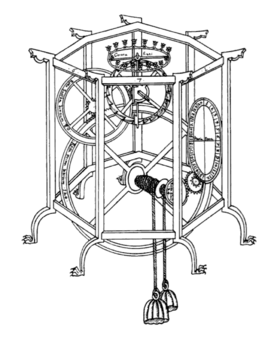
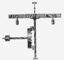
The balance wheel appeared with the first mechanical clocks, in 14th century Europe, but it seems unknown exactly when or where it was first used. It is an improved version of the foliot, an early inertial timekeeper consisting of a straight bar pivoted in the center with weights on the ends, which oscillates back and forth. The foliot weights could be slid in or out on the bar, to adjust the rate of the clock. The first clocks in northern Europe used foliots, while those in southern Europe used balance wheels.[7] As clocks were made smaller, first as bracket clocks and lantern clocks and then as the first large watches after 1500, balance wheels began to be used in place of foliots.[8] Since more of its weight is located on the rim away from the axis, a balance wheel could have a larger moment of inertia than a foliot of the same size, and keep better time. The wheel shape also had less air resistance, and its geometry partly compensated for thermal expansion error due to temperature changes.[9]
Addition of balance spring
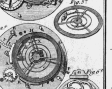
These early balance wheels were crude timekeepers because they lacked the other essential element: the balance spring. Early balance wheels were pushed in one direction by the escapement until the verge flag that was in contact with a tooth on the escape wheel slipped past the tip of the tooth ("escaped") and the action of the escapement reversed, pushing the wheel back the other way. In such an "inertial' wheel, the acceleration is proportional to the drive force. In a clock or watch without balance spring, the drive force provides both the force that accelerates the wheel and also the force that slows it down and reverses it. If the drive force is increased, both acceleration and deceleration are increased, this results in the wheel getting pushed back and forth faster. This made the timekeeping strongly dependent on the force applied by the escapement. In a watch the drive force provided by the mainspring, applied to the escapement through the timepiece's gear train, declined during the watch's running period as the mainspring unwound. Without some means of equalizing the drive force, the watch slowed down during the running period between windings as the spring lost force, causing it to lose time. This is why all pre-balance spring watches required fusees (or in a few cases stackfreeds) to equalize the force from the mainspring reaching the escapement, to achieve even minimal accuracy.[10] Even with these devices, watches prior to the balance spring were very inaccurate.
The idea of the balance spring was inspired by observations that springy hog bristle curbs, added to limit the rotation of the wheel, increased its accuracy.[11][12] Robert Hooke first applied a metal spring to the balance in 1658 and Jean de Hautefeuille and Christiaan Huygens improved it to its present spiral form in 1674[9][13] The addition of the spring made the balance wheel a harmonic oscillator, the basis of every modern clock. This means the wheel vibrated at a natural resonant frequency or ‘beat’ and resisted changes in its vibration rate caused by friction or changing drive force. This crucial innovation greatly increased the accuracy of watches, from several hours per day[14] to perhaps 10 minutes per day,[15] changing them from expensive novelties into useful timekeepers.
Temperature error
After the balance spring was added, a major remaining source of inaccuracy was the effect of temperature changes. Early watches had balance springs made of plain steel and balances of brass or steel, and the influence of temperature on these noticeably affected the rate.
An increase in temperature increases the dimensions of the balance spring and the balance due to thermal expansion. The strength of a spring, the restoring force it produces in response to a deflection, is proportional to its breadth and the cube of its thickness, and inversely proportional to its length. An increase in temperature would actually make a spring stronger if it affected only its physical dimensions. However, a much larger effect in a balance spring made of plain steel is that the elasticity of the spring's metal decreases significantly as the temperature increases, the net effect being that a plain steel spring becomes weaker with increasing temperature. An increase in temperature also increases diameter of a steel or brass balance wheel, increasing its rotational inertia, its moment of inertia, making it harder for the balance spring to accelerate. The two effects of increasing temperature on physical dimensions of the spring and the balance, the strengthening of the balance spring and the increase in rotational inertia of the balance, have opposing effects and to an extent cancel each other.[16] The major effect of temperature which affects the rate of a watch is the weakening of the balance spring with increasing temperature.
In a watch that is not compensated for the effects of temperature the weaker spring takes longer to return the balance wheel back toward the center, so the ‘beat’ gets slower and the watch loses time. Ferdinand Berthoud found in 1773 that an ordinary brass balance and steel hairspring, subjected to a 60 °F (33 °C) temperature increase, loses 393 seconds (6 1/2 minutes) per day, of which 312 seconds is due to spring elasticity decrease.[17]
Temperature-compensated balance wheels
The need for an accurate clock for celestial navigation during sea voyages drove many advances in balance technology in 18th century Britain and France. Even a 1-second per day error in a marine chronometer could result in a 17-mile error in ship's position after a 2-month voyage. John Harrison was first to apply temperature compensation to a balance wheel in 1753, using a bimetallic ‘compensation curb’ on the spring, in the first successful marine chronometers, H4 and H5. These achieved an accuracy of a fraction of a second per day,[15] but the compensation curb was not further used because of its complexity.
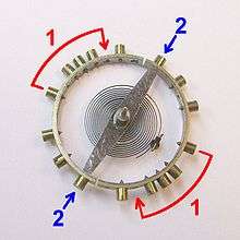
A simpler solution was devised around 1765 by Pierre Le Roy, and improved by John Arnold, and Thomas Earnshaw: the Earnshaw or compensating balance wheel.[18] The key was to make the balance wheel change size with temperature. If the balance could be made to shrink in diameter as it got warmer, the smaller moment of inertia would compensate for the weakening of the balance spring, keeping the period of oscillation the same.
To accomplish this, the outer rim of the balance was made of a ‘sandwich’ of two metals; a layer of steel on the inside fused to a layer of brass on the outside. Strips of this bimetallic construction bend toward the steel side when they are warmed, because the thermal expansion of brass is greater than steel. The rim was cut open at two points next to the spokes of the wheel, so it resembled an S-shape (see figure) with two circular bimetallic ‘arms’. These wheels are sometimes referred to as "Z-balances". A temperature increase makes the arms bend inward toward the center of the wheel, and the shift of mass inward reduces the moment of inertia of the balance, similar to the way a spinning ice skater can reduce her moment of inertia by pulling in her arms. This reduction in the moment of inertia compensated for the reduced torque produced by the weaker balance spring. The amount of compensation is adjusted by moveable weights on the arms. Marine chronometers with this type of balance had errors of only 3–4 seconds per day over a wide temperature range.[19] By the 1870s compensated balances began to be used in watches.
Middle temperature error

The standard Earnshaw compensation balance dramatically reduced error due to temperature variations, but it didn't eliminate it. As first described by J. G. Ulrich, a compensated balance adjusted to keep correct time at a given low and high temperature will be a few seconds per day fast at intermediate temperatures.[20] The reason is that the moment of inertia of the balance varies as the square of the radius of the compensation arms, and thus of the temperature. But the elasticity of the spring varies linearly with temperature.
To mitigate this problem, chronometer makers adopted various 'auxiliary compensation' schemes, which reduced error below 1 second per day. Such schemes consisted for example of small bimetallic arms attached to the inside of the balance wheel. Such compensators could only bend in one direction toward the center of the balance wheel, but bending outward would be blocked by the wheel itself. The blocked movement causes a non-linear temperature response that could slightly better compensate the elasticity changes in the spring. Most of the chronometers that came in first in the annual Greenwich Observatory trials between 1850 and 1914 were auxiliary compensation designs.[21] Auxiliary compensation was never used in watches because of its complexity.
Better materials
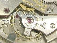
The bimetallic compensated balance wheel was made obsolete in the early 20th century by advances in metallurgy. Charles Édouard Guillaume won a Nobel prize for the 1896 invention of Invar, a nickel steel alloy with very low thermal expansion, and Elinvar (Elasticité invariable) an alloy whose elasticity is unchanged over a wide temperature range, for balance springs.[22] A solid Invar balance with a spring of Elinvar was largely unaffected by temperature, so it replaced the difficult-to-adjust bimetallic balance. This led to a series of improved low temperature coefficient alloys for balances and springs.
Before developing Elinvar, Guillaume also invented an alloy to compensate for middle temperature error in bimetallic balances by endowing it with a negative quadratic temperature coefficient. This alloy, named anibal, is a slight variation of invar. It almost completely negated the temperature effect of the steel hairspring, but still required a bimetal compensated balance wheel, known as a Guillaume balance wheel. This design later fell out of use in favor of single metal Invar balances with Elinvar springs. The quadratic coefficient is defined by its place in the equation of expansion of a material;[23]
- where;
- is the length of the sample at some reference temperature
- is the temperature above the reference
- is the length of the sample at temperature
- is the linear coefficient of expansion
- is the quadratic coefficient of expansion
References
- "Marine Chronometer". Encyclopædia Britannica online. Encyclopædia Britannica Inc. 2007. Retrieved 2007-06-15.
- Britten, Frederick J. (1898). On the Springing and Adjusting of Watches. New York: Spon & Chamberlain. Retrieved 2008-04-20.. Has detailed account of development of balance spring.
- Brearley, Harry C. (1919). Time Telling through the Ages. New York: Doubleday. Retrieved 2008-04-16..
- Glasgow, David (1885). Watch and Clock Making. London: Cassel & Co. Retrieved 2008-04-16.. Detailed section on balance temperature error and auxiliary compensation.
- Gould, Rupert T. (1923). The Marine Chronometer. Its History and Development. London: J. D. Potter. pp. 176–177. ISBN 0-907462-05-7.
- Headrick, Michael (2002). "Origin and Evolution of the Anchor Clock Escapement". Control Systems magazine, Inst. of Electrical and Electronic Engineers. 22 (2). Archived from the original on 2009-10-25. Retrieved 2007-06-06.. Good engineering overview of development of clock and watch escapements, focusing on sources of error.
- Milham, Willis I. (1945). Time and Timekeepers. New York: MacMillan. ISBN 0-7808-0008-7.. Comprehensive 616 p. book by astronomy professor, good account of origin of clock parts, but historical research dated. Long bibliography.
- Odets, Walt (2005). "Balance Wheel Assembly". Glossary of Watch Parts. TimeZone Watch School. Archived from the original on 14 June 2007. Retrieved 2007-06-15.. Detailed illustrations of parts of a modern watch, on watch repair website
- Odets, Walt (2007). "The Balance Wheel of a Watch". The Horologium. TimeZone.com. Archived from the original on 6 July 2007. Retrieved 2007-06-15.. Technical article on construction of watch balance wheels, starting with compensation balances, by a professional watchmaker, on a watch repair website.
External links
- Choi, Fred (2007-05-26). "William Simcock Massey Type III pocket watch". YouTube. Retrieved 2008-04-26. Video of antique mid-19th century watch showing the balance wheel turning
- Costa, Alan (1998). "The History of Watches". Atmos Man. Archived from the original on 2007-07-17. Retrieved 2007-06-19. History of watches, on commercial website.
- Markl, Xavier (2016). "Monochrome-Watches A technical perspective the regulating organ of the watch". Monochrome-Watches A technical perspective the regulating organ of the watch
- Oliver Mundy, The Watch Cabinet Pictures of a private collection of antique watches from 1710 to 1908, showing many different varieties of balance wheel.
Footnotes
- Odets, Walt (2007). "The Balance Wheel of a Watch". The Horologium. TimeZone.com. Archived from the original on 6 July 2007. Retrieved 2007-06-16.
- Odets, Walt (2005). "Balance Wheel Assembly". Glossary of Watch Parts. TimeZone Watch School. Retrieved 2007-06-15.
- Arnstein, Walt (2007). "Does faster mean more accurate?, TimeZone.com". Archived from the original on 2007-06-08. Retrieved 2007-06-15.
- Schlitt, Wayne (2002). "The Elgin Collector's Site". Retrieved 2007-06-20.
- "Archived copy". Archived from the original on 2009-12-28. Retrieved 2009-09-18.CS1 maint: archived copy as title (link)
- "Marine Chronometer". Encyclopædia Britannica online. Encyclopædia Britannica Inc. 2007. Retrieved 2007-06-15.
- White, Lynn Jr. (1966). Medieval Technology and Social Change. Oxford Press. ISBN 978-0-19-500266-9., p. 124
- Milham, Willis I. (1945). Time and Timekeepers. New York: MacMillan. ISBN 0-7808-0008-7., p. 92
- Headrick, Michael (2002). "Origin and Evolution of the Anchor Clock Escapement". Control Systems magazine, Inst. of Electrical and Electronic Engineers. 22 (2). Archived from the original on 2009-10-25. Retrieved 2007-06-06.
- "Brittens Old Clocks & Watches" Edited by Cecil Clutton, G H Baillie & C A Ilbert, Ninth Edition Revised and Enlarged by Cecil Clutton. Bloomsbury Books London 1986 ISBN 0906223695 page 16
- Britten, Frederick J. (1898). On the Springing and Adjusting of Watches. New York: Spon & Chamberlain. Retrieved 2008-04-16. p. 9
- Brearley, Harry C. (1919). Time Telling through the Ages. New York: Doubleday. Retrieved 2008-04-16. pp. 108–109
- Milham 1945, p. 224
- Milham 1945, p. 226
- "A Revolution in Timekeeping, part 3". A Walk Through Time. NIST (National Inst. of Standards and Technology). 2002. Archived from the original on 2007-05-28. Retrieved 2007-06-06.
- A.L. Rawlings, Timothy Treffry, The Science of Clocks and Watches, Publisher: BHI, ISBN 0 9509621 3 9, Edition: 1993, 3rd enlarged and revised edition.
- Britten 1898, p. 37
- Milham 1945, p. 233
- Glasgow, David (1885). Watch and Clock Making. London: Cassel & Co. Retrieved 2008-04-16. p. 227
- Gould, Rupert T. (1923). The Marine Chronometer. Its History and Development. London: J. D. Potter. ISBN 0-907462-05-7. pp. 176–177
- Gould 1923, pp. 265–266
- Milham 1945, p. 234
- Gould, p. 201.
