Air preheater
An air preheater (APH) is any device designed to heat air before another process (for example, combustion in a boiler) with the primary objective of increasing the thermal efficiency of the process. They may be used alone or to replace a recuperative heat system or to replace a steam coil.

In particular, this article describes the combustion air preheaters used in large boilers found in thermal power stations producing electric power from e.g. fossil fuels, biomass or waste.[1][2][3][4][5] For instance, as the Ljungström air preheater has been attributed worldwide fuel savings estimated to 4,960,000,000 tons of oil, "few inventions have been as successful in saving fuel as the Ljungström Air Preheater", marked as the 44th International Historic Mechanical Engineering Landmark by the American Society of Mechanical Engineers.[6]
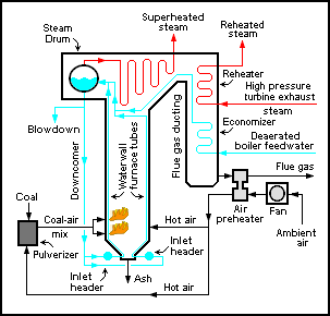
The purpose of the air preheater is to recover the heat from the boiler flue gas which increases the thermal efficiency of the boiler by reducing the useful heat lost in the flue gas. As a consequence, the flue gases are also conveyed to the flue gas stack (or chimney) at a lower temperature, allowing simplified design of the conveyance system and the flue gas stack. It also allows control over the temperature of gases leaving the stack (to meet emissions regulations, for example). It is installed between the economizer and chimney.
Types
There are two types of air preheaters for use in steam generators in thermal power stations: One is a tubular type built into the boiler flue gas ducting, and the other is a regenerative air preheater.[1][2][7] These may be arranged so the gas flows horizontally or vertically across the axis of rotation.
Another type of air preheater is the regenerator used in iron or glass manufacture.
Tubular type
Construction features
Tubular preheaters consist of straight tube bundles which pass through the outlet ducting of the boiler and open at each end outside of the ducting. Inside the ducting, the hot furnace gases pass around the preheater tubes, transferring heat from the exhaust gas to the air inside the preheater. Ambient air is forced by a fan through ducting at one end of the preheater tubes and at other end the heated air from inside of the tubes emerges into another set of ducting, which carries it to the boiler furnace for combustion.
Problems
The tubular preheater ductings for cold and hot air require more space and structural supports than a rotating preheater design. Further, due to dust-laden abrasive flue gases, the tubes outside the ducting wear out faster on the side facing the gas current. Many advances have been made to eliminate this problem such as the use of ceramic and hardened steel.
Many new circulating fluidized bed (CFB) and bubbling fluidized bed (BFB) steam generators are currently incorporating tubular air heaters offering an advantage with regards to the moving parts of a rotary type.
Dew point corrosion
Dew point corrosion occurs for a variety of reasons.[8][9] The type of fuel used, its sulfur content and moisture content are contributing factors. However, by far the most significant factor in dew point corrosion is the metal temperature of the tubes. If the metal temperature within the tubes drops below the acid saturation temperature, usually at between 190 °F (88 °C) and 230 °F (110 °C), but sometimes at temperatures as high as 260 °F (127 °C), then the risk of dew point corrosion damage becomes considerable.
Regenerative air preheaters
There are two types of regenerative air preheaters: the rotating-plate regenerative air preheaters (RAPH) and the stationary-plate regenerative air preheaters (Rothemuhle).[1][2][3][10]
Rotating-plate regenerative air preheater

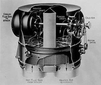
The rotating-plate design (RAPH)[2] consists of a central rotating-plate element installed within a casing that is divided into two (bi-sector type), three (tri-sector type) or four (quad-sector type) sectors containing seals around the element. The seals allow the element to rotate through all the sectors, but keep gas leakage between sectors to a minimum while providing separate gas air and flue gas paths through each sector.
Tri-sector types are the most common in modern power generation facilities.[12] In the tri-sector design, the largest sector (usually spanning about half the cross-section of the casing) is connected to the boiler hot gas outlet. The hot exhaust gas flows over the central element, transferring some of its heat to the element, and is then ducted away for further treatment in dust collectors and other equipment before being expelled from the flue gas stack. The second, smaller sector, is fed with ambient air by a fan, which passes over the heated element as it rotates into the sector, and is heated before being carried to the boiler furnace for combustion. The third sector is the smallest one and it heats air which is routed into the pulverizers and used to carry the coal-air mixture to coal boiler burners. Thus, the total air heated in the RAPH provides: heating air to remove the moisture from the pulverised coal dust, carrier air for transporting the pulverised coal to the boiler burners and the primary air for combustion.
The rotor itself is the medium of heat transfer in this system, and is usually composed of some form of steel and/or ceramic structure. It rotates quite slowly (around 1-2 RPM) to allow optimum heat transfer first from the hot exhaust gases to the element, then as it rotates, from the element to the cooler air in the other sectors.
Construction features
In this design the whole air preheater casing is supported on the boiler supporting structure itself with necessary expansion joints in the ducting.
The vertical rotor is supported on thrust bearings at the lower end and has an oil bath lubrication, cooled by water circulating in coils inside the oil bath. This arrangement is for cooling the lower end of the shaft, as this end of the vertical rotor is on the hot end of the ducting. The top end of the rotor has a simple roller bearing to hold the shaft in a vertical position.
The rotor is built up on the vertical shaft with radial supports and cages for holding the baskets in position. Radial and circumferential seal plates are also provided to avoid leakages of gases or air between the sectors or between the duct and the casing while in rotation.
For on line cleaning of the deposits from the baskets steam jets are provided such that the blown out dust and ash are collected at the bottom ash hopper of the air preheater. This dust hopper is connected for emptying along with the main dust hoppers of the dust collectors.
The rotor is turned by an air driven motor and gearing, and is required to be started before starting the boiler and also to be kept in rotation for some time after the boiler is stopped, to avoid uneven expansion and contraction resulting in warping or cracking of the rotor. The station air is generally totally dry (dry air is required for the instrumentation), so the air used to drive the rotor is injected with oil to lubricate the air motor.
Safety protected inspection windows are provided for viewing the preheater's internal operation under all operating conditions.
The baskets are in the sector housings provided on the rotor and are renewable. The life of the baskets depend on the ash abrasiveness and corrosiveness of the boiler outlet gases.
Problems
The boiler flue gas contains many dust particles (due to high ash content) not contributing towards combustion, such as silica, which cause abrasive wear of the baskets, and may also contain corrosive gases depending on the composition of the fuel. For example, Indian coals generally result in high levels of ash and silica in the flue gas. The wear of the baskets therefore is generally more than other, cleaner-burning fuels.
In this RAPH, the dust laden, corrosive boiler gases have to pass between the elements of air preheater baskets. The elements are made up of zig zag corrugated plates pressed into a steel basket giving sufficient annular space in between for the gas to pass through. These plates are corrugated to give more surface area for the heat to be absorbed and also to give it the rigidity for stacking them into the baskets. Hence frequent replacements are called for and new baskets are always kept ready. In the early days, Cor-ten steel was being used for the elements. Today due to technological advance many manufacturers may use their own patents. Some manufacturers supply different materials for the use of the elements to lengthen the life of the baskets.
In certain cases the unburnt deposits may occur on the air preheater elements causing it to catch fire during normal operations of the boiler, giving rise to explosions inside the air preheater. Sometimes mild explosions may be detected in the control room by variations in the inlet and outlet temperatures of the combustion air.

Stationary-plate regenerative air preheater
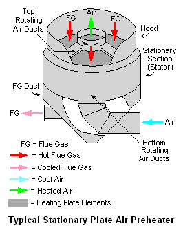
The heating plate elements in this type of regenerative air preheater are also installed in a casing, but the heating plate elements are stationary rather than rotating. Instead the air ducts in the preheater are rotated so as to alternatively expose sections of the heating plate elements to the upflowing cool air.[1][2][3]
As indicated in the adjacent drawing, there are rotating inlet air ducts at the bottom of the stationary plates similar to the rotating outlet air ducts at the top of the stationary plates.[13]
Stationary-plate regenerative air preheaters are also known as Rothemuhle preheaters, manufactured for over 25 years by Balke-Dürr GmbH of Ratingen, Germany.
Regenerator
A regenerator consists of a brick checkerwork: bricks laid with spaces equivalent to a brick's width between them, so that air can flow relatively easily through the checkerwork. The idea is that as hot exhaust gases flow through the checkerwork, they give up heat to the bricks. The airflow is then reversed, so that the hot bricks heat up the incoming combustion air and fuel. For a glass-melting furnace, a regenerator sits on either side of the furnace, often forming an integral whole. For a blast furnace, the regenerators (commonly called Cowper stoves) sit separate to the furnace. A furnace needs no less than two stoves, but may have three. One of the stoves is 'on gas', receiving hot gases from the furnace top and heating the checkerwork inside, whilst the other is 'on blast', receiving cold air from the blowers, heating it and passing it to the blast furnace.
See also
- Recuperator
- Economiser
- Regenerative heat exchanger
- Thermal wheel
References
- Sadik Kakaç; Hongtan Liu (2002). Heat Exchangers: Selection, Rating and Thermal Design (2nd ed.). CRC Press. ISBN 0-8493-0902-6.
- Babcock & Wilcox Co. (2005). Steam: Its Generation and Use (41st ed.). ISBN 0-9634570-0-4.
- Sadik Kakaç (Editor) (April 1991). Boilers. Evaporators and Condensers. Wiley Interscience. ISBN 0-471-62170-6.CS1 maint: extra text: authors list (link) (See Chapter 8 by Z.H. Lin)
- British Electricity International (1991). Modern Power Station Practice: incorporating modern power system practice (3rd Edition (12 volume set) ed.). Pergamon. ISBN 0-08-040510-X.
- Thomas C. Elliott; Kao Chen; Robert Swanekamp (1997). Standard Handbook of Powerplant Engineering (2nd ed.). McGraw-Hill Professional. ISBN 0-07-019435-1.
- "The Ljungström Air Preheater 1920". asme.org. American Society of Mechanical Engineers. June 21, 1995. Archived from the original on October 20, 2016. Retrieved April 5, 2019.
- "Trisector Ljungström Air Preheater". Archived from the original on 2007-09-28. Retrieved 2007-05-24.
- Examples of dewpoint corrosion
- More examples of dewpoint corrosion
- Lawrence Drbak, Patrica Boston, Kalya Westra, and R. Bruce Erickson (Editors) (1996). Power Plant Engineering (Black and Veatch). Chapman & Hall. ISBN 0-412-06401-4.CS1 maint: uses authors parameter (link)
- Course SI:428A Online publication of the U.S. Environmental Protection Agency's Air Pollution Training Institute, known as APTI (Scroll down to page 23 of 28)
- Air preheaters: Rotating regenerative heat exchangers
- "Duct cleaning guide". Tuesday, 11 June 2019