Introduction
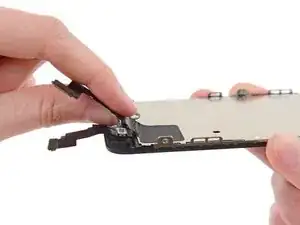
Use this guide to replace the upper display assembly cable, including the front-facing camera, microphone, and other sensors.
Tools
Parts
-
-
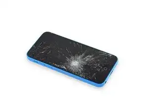
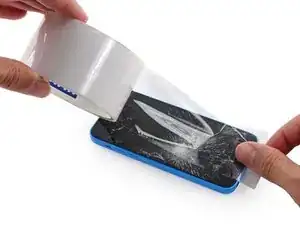
If your display glass is cracked, keep further breakage contained and prevent bodily harm during your repair by taping the glass.
-
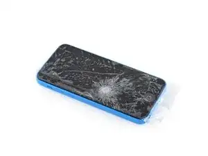
Lay overlapping strips of clear packing tape over the iPhone's display until the whole face is covered.
-
-
-
Power off your iPhone before beginning disassembly.
-
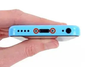
Remove the two 3.8 mm P2 Pentalobe screws on either side of the Lightning connector.
-
-
-
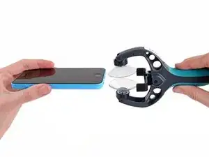
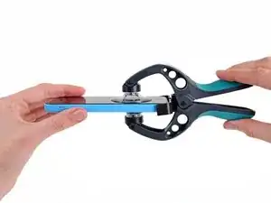
Close the handle on the iSclack, opening the suction-cup jaws.
-
Place the bottom of your iPhone in between the suction cups, against the plastic depth gauge.
-
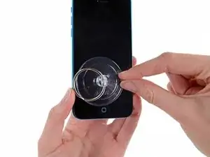
The top suction cup should rest just above the home button.
-
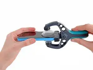
Open the handles to close the jaws of the iSclack. Center the suction cups and press them firmly onto the top and bottom of the iPhone.
-
-
-
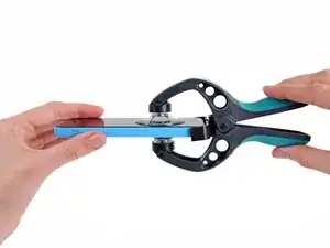
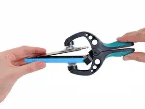
Hold onto your iPhone securely and close the handle of the iSclack to separate the suction cups, pulling the front panel up from the rear case.
-
The iSclack is designed to safely open your iPhone just enough to separate the pieces, but not enough to damage any cables.
-
Skip the next three steps and continue on to Step 8.
-
-
-
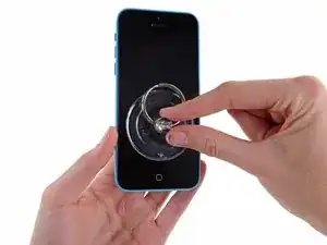
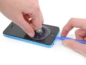
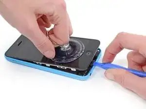
While holding the iPhone down with one hand, pull up on the suction cup to slightly separate the front panel assembly from the rear case.
-
With a plastic opening tool, begin to gently pry the rear case down, away from the display assembly, while you pull up with the suction cup.
-
-
-
Pull the plastic nub to release the vacuum seal on the suction cup.
-
Remove the suction cup from the display assembly.
-
-
-
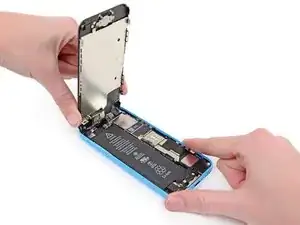
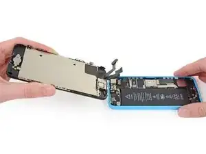
Lift the home button end of the front panel up to gain access to the connectors near the top of the phone.
-
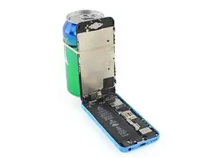
Open the display to about a 90º angle, and lean it against something to keep it propped up while you're working on the phone.
-
In a pinch, you can use an unopened canned beverage to hold the display.
-
Add a rubber band to keep the display securely in place while you work. This prevents undue strain on the display cables.
-
-
-
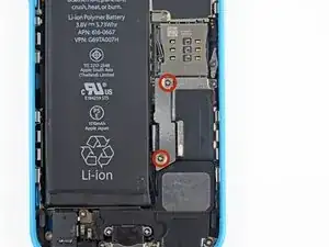
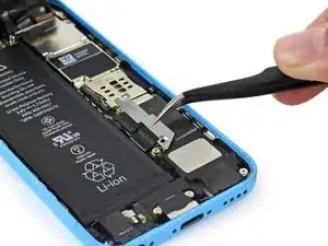
Remove the two 1.6 mm Phillips #000 screws securing the metal battery connector bracket to the logic board.
-
-
-
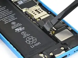
Use a spudger or a clean fingernail to gently pry the battery connector up from its socket on the logic board.
-
-
-
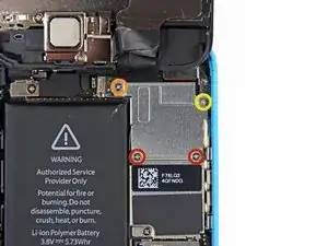
Remove the following Phillips #000 screws securing the front panel assembly cable bracket to the logic board:
-
Two 1.3 mm screws
-
One 1.7 mm screw
-
One 3.25 mm screw
-
-
-
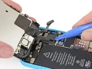
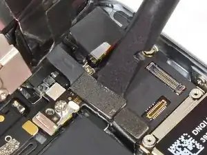
Use a plastic opening tool or a fingernail to disconnect the front-facing camera and sensor cable connector.
-
-
-
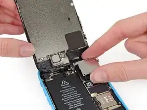
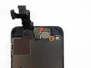
Remove two Phillips #000 screws securing the upper component bracket to the display assembly.
-
One 4.2 mm screw
-
One 2.3 mm screw
-
-
-
Use the flat edge of a spudger to push the earpiece speaker bracket off the display assembly.
-
-
-
The front-facing camera and sensor cable is adhered to the display assembly with mild adhesive.
-
While this step is not required, it will decrease the chances of damaging the delicate cable assembly.
-
-
-
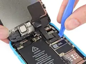
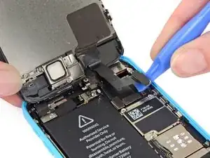
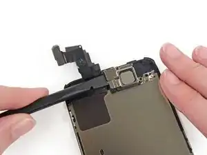
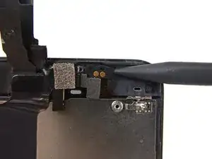
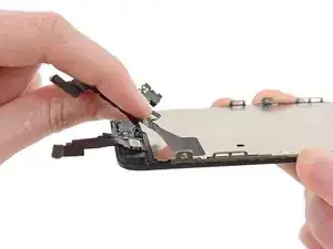
Using the pointed end of a spudger, gently pry the earpiece speaker contact cable up, to separate this portion of the camera and sensor cable from the adhesive below.
-
-
-
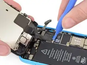
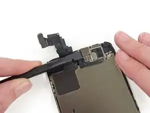
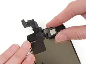
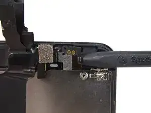
Slide the point of a spudger under the microphone to lift it out of its recess in the display assembly.
-
-
-
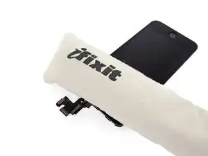
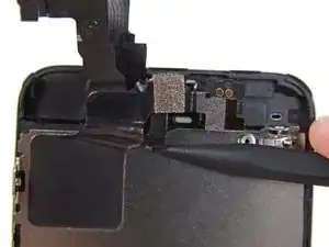
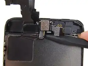
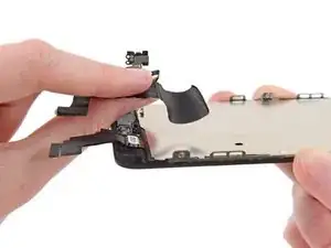
Carefully peel the cable assembly off of the LCD shield plate to remove it from the display.
-
To reassemble your device, follow these instructions in reverse order.
2 comments
Super Easy to complete, just make sure you use a jar lid or something to keep all the screws together.
I use a double sided sticky tape, stick to the table and stick down the screws onto it with a piece of paper to say where it came from.
When reassembling the camera will it just stick back on?
