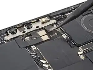
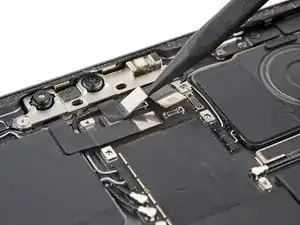
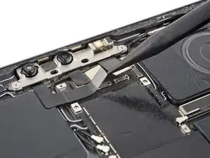
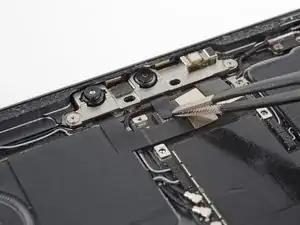
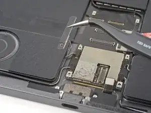
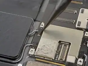
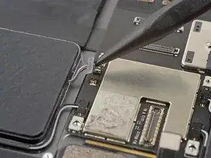
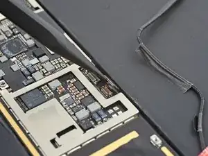
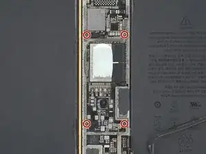
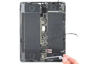
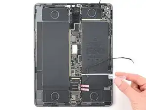
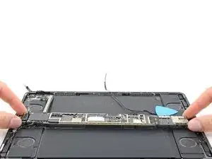
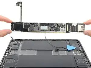
Introduction

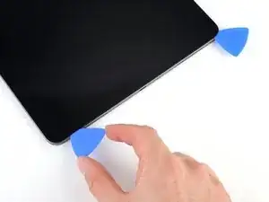
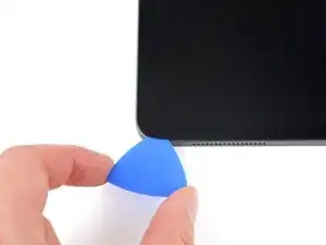
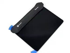
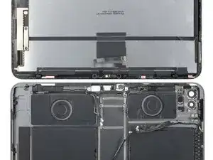
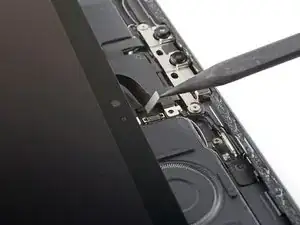
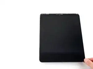
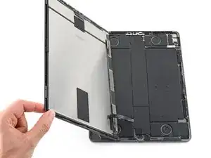
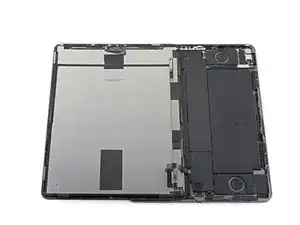
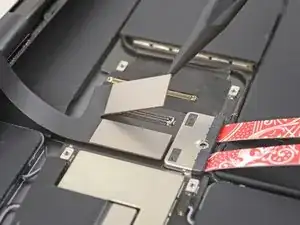
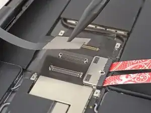
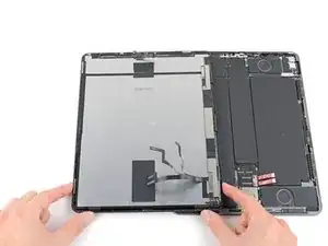
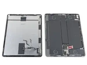
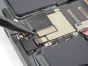
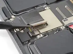
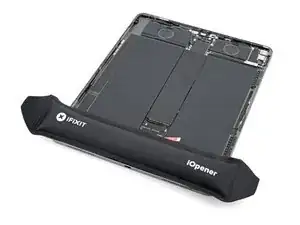
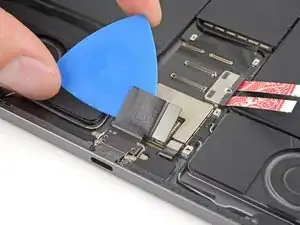
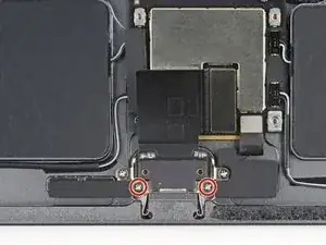
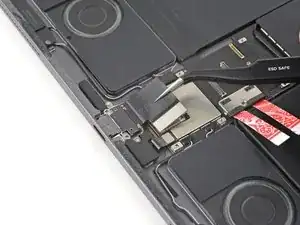
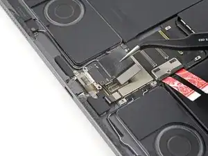
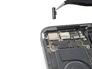
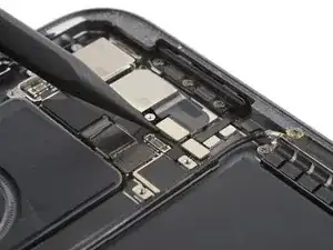
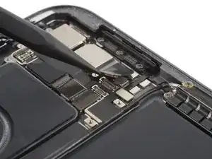
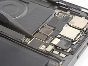
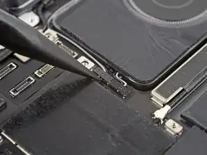
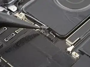
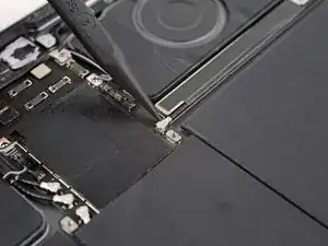
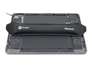
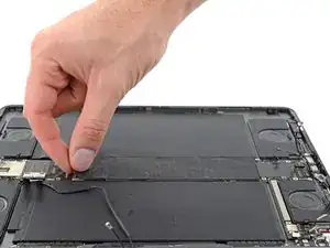
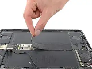
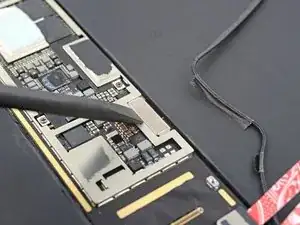
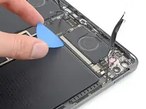
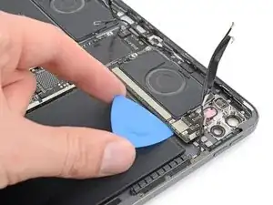
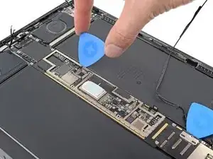
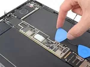
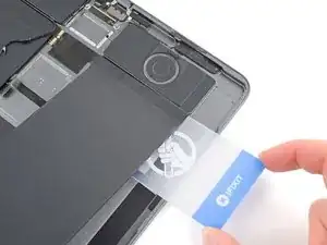
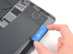
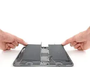
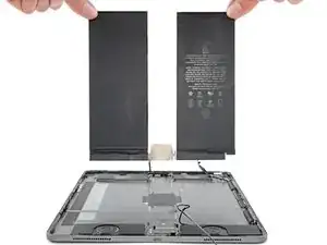
Follow this guide to replace the battery in your iPad Pro 12.9" 4th generation.

This guide is written with an A2229 (Wi-Fi only) model iPad Pro. If you have the cellular model, use this guide as a general reference, but you may need to perform extra disassembly not covered in this guide.

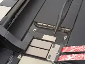
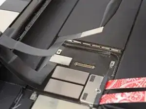
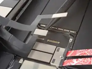
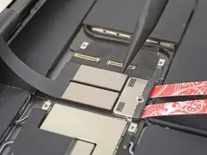
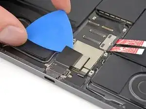
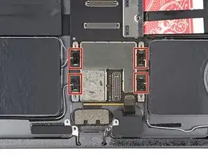
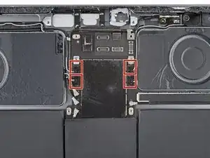
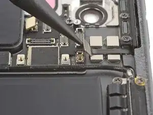
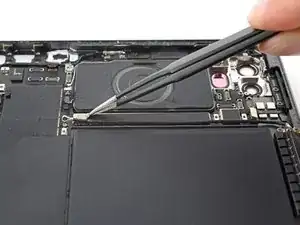
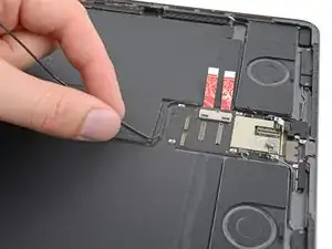
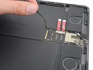
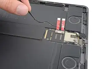
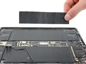
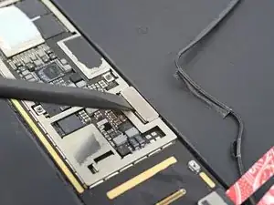
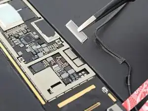
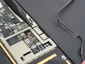
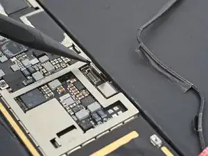
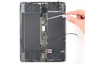
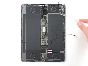
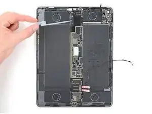
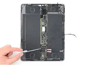
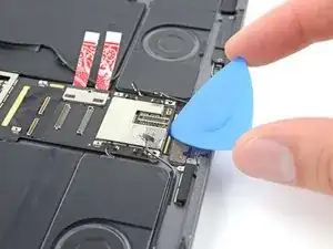
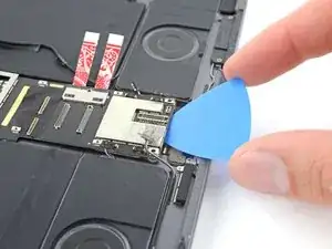
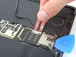
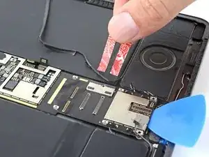
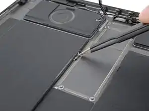
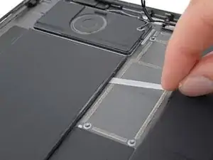
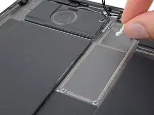
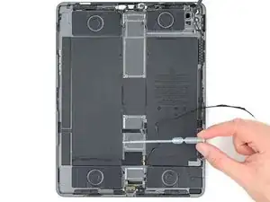
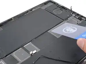
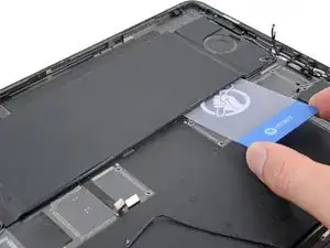
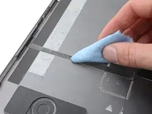
Some photos show the battery connector blocked with two card strips. While this is an optional method, it's more reliable to fully discharge the battery. Ignore this visual discrepancy as you work through the guide.

If your battery is swollen, take appropriate precautions.

  1. YWVxO1movQWwpRq4
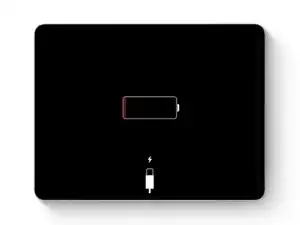
    • Allow your iPad's battery to fully drain before starting this repair. A charged battery may catch fire if damaged during the repair.

    • Unplug any cables and fully shut down your iPad.

  2. BtVWQ52HEFXlHOYx
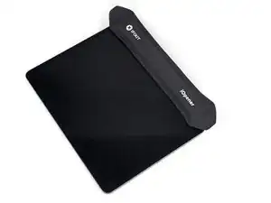
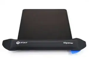
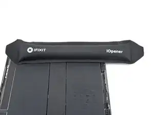
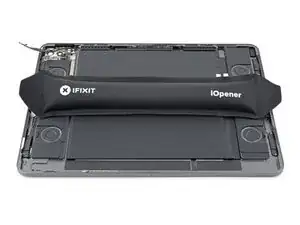
    • Apply a heated iOpener to the right edge of the screen for two minutes.

    • A hair dryer, heat gun, or hot plate may also be used, but be careful not to overheat the iPad—the screen and internal battery are susceptible to heat damage.

  3. DObFBlhi61YxuBmr
    DObFBlhi61YxuBmr
    QqKSattfyuKGYnRr
    lPfEAEkmVSuTVLjt
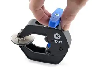
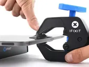
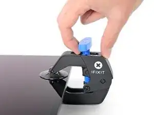
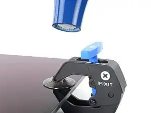
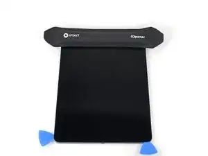
    • The next three steps demonstrate the Anti-Clamp, a tool we designed to make the opening procedure easier. If you aren't using the Anti-Clamp, skip down three steps for an alternate method.

    • For complete instructions on how to use the Anti-Clamp, check out this guide.

    • Pull the blue handle backwards to unlock the Anti-Clamp's arms.

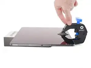
    • Place an object under your iPad so it rests level between the suction cups.

    • Position the suction cups near the middle of the right edge—one on the top, and one on the bottom.

    • Hold the bottom of the Anti-Clamp steady and firmly press down on the top cup to apply suction.

    • If you find that the surface of your iPad is too slippery for the Anti-Clamp to hold onto, use tape to create a grippier surface.

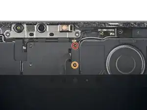
  4. KPJi64XxZ1tOfQVY
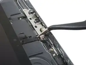
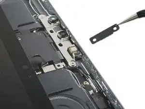
    KPJi64XxZ1tOfQVY
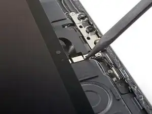
    gZxL5CQsqOxYfdPf
    rVKsNwHgnKpim6DT
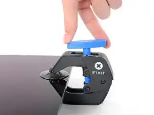
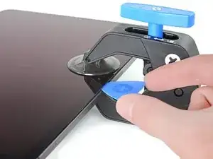
    • Pull the blue handle forward to lock the arms.

    • Turn the handle clockwise 360 degrees or until the cups start to stretch.

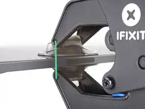
    • Make sure the suction cups remain aligned with each other. If they begin to slip out of alignment, loosen the suction cups slightly and realign the arms.

  5. 5LHZ5p5OrYllfETQ
    5LHZ5p5OrYllfETQ
    gScO5MikrOmnEhaF
    • Wait one minute to give the adhesive a chance to release and present an opening gap.

    • If your screen isn't getting hot enough, you can use a hair dryer to heat along the right edge of the iPad.

    • For complete instructions on how to use a hair dryer, check out this guide.

    • Insert an opening pick under the screen when the Anti-Clamp creates a large enough gap.

    • If the Anti-Clamp doesn't create a sufficient gap, apply more heat to the area and rotate the handle clockwise half a turn.

    • Don't crank more than a half a turn at a time, and wait one minute between turns. Let the Anti-Clamp and time do the work for you.

    • Skip the next step.

  6. t3B3cJNOAAtOwhdX
    t3B3cJNOAAtOwhdX
    YPBU6mDj1CBdSDPt
    PHBvtyicBV3YINLQ
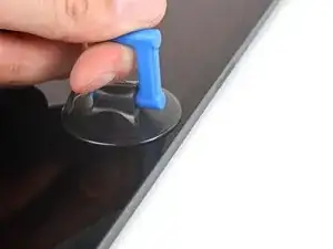
    • If your screen is badly cracked, covering it with a layer of clear packing tape may allow the suction cup to adhere. Alternatively, very strong tape may be used instead of the suction cup. If all else fails, you can superglue the suction cup to the broken screen.

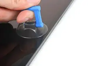
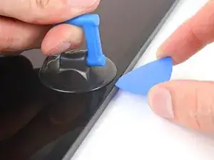
    • Apply a suction handle to the screen as close to the center of the right edge as possible.

    • Pull up on the suction handle with a strong, steady force to create a small gap between the frame and screen.

    • The large screen is very fragile. Only create a gap big enough to insert an opening pick.

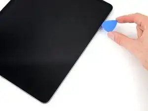
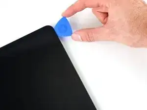
    • Insert an opening pick into the gap.

    • Don't insert the pick more than 5 mm to avoid damaging the screen.

  7. RFeLgSDFtGgHapMN
    RFeLgSDFtGgHapMN
    CaZg2gGlPuPds2ke
    YAWLHwiQFdakdprA
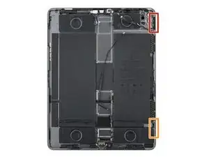
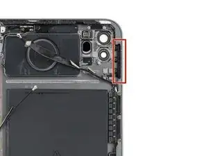
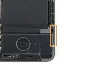
    • Along the frame's right edge, there are two cutouts for the screen magnets where the adhesive is very thin. As you slice along this edge in the next step, don't insert your opening pick deeper than 2 mm in these locations:

    • One magnet begins 2 cm from the top edge and is 2.5 cm long.

    • The second magnet begins 3 cm from the bottom edge and is 2.5 cm long.

  8. BMfIJOkWqkI5Y5ji
    BMfIJOkWqkI5Y5ji
    MxSwT6kWHC5OBK4D
    EYeM4uqTvx4VgmiY
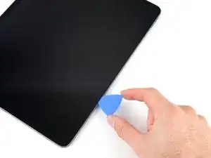
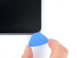
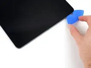
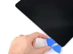
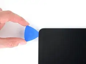
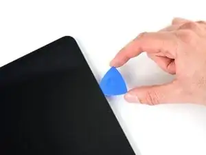
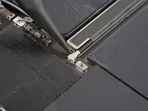
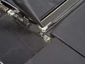
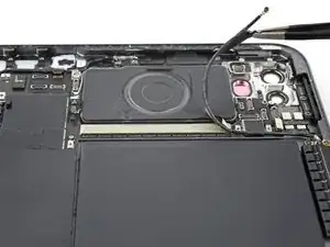
    • Slide your opening pick back and forth along the right edge of the screen to slice the adhesive.

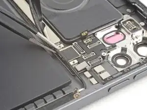
    • Angle your pick downward and insert it no more than 2 mm near the magnet cutouts and 5 mm everywhere else.

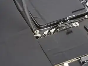
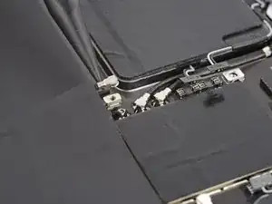
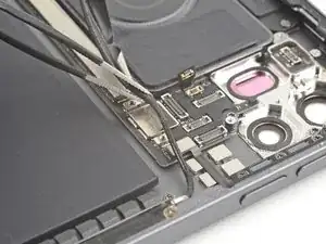
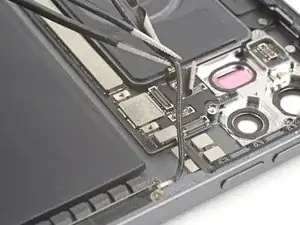
  9. fW2Vs5bsRXITJmR2
    fW2Vs5bsRXITJmR2
    PXijmWSEWdAuq2mN
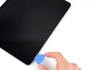
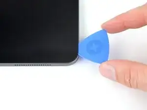
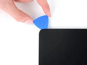
    • Rotate your opening pick around the bottom right corner of the screen.

    • Leave your pick in the bottom right corner to prevent the adhesive from resealing.

  10. DxLQcapNWYoxNQeH
    • Apply a heated iOpener to the bottom edge of the screen for two minutes.

    • A hair dryer, heat gun, or hot plate may also be used, but be careful not to overheat the iPad—the screen and internal battery are susceptible to heat damage.

  11. HJOqXNPfIDyZTWC5
    HJOqXNPfIDyZTWC5
    EJaydKJYSYMkQNgy
    wghWd1KIg5XaavKP
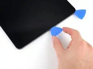
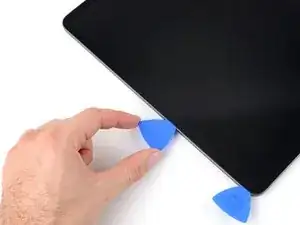
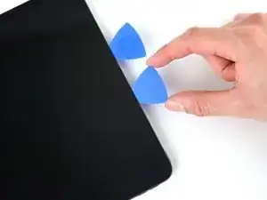
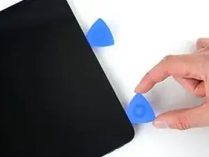
    • Insert a second opening pick in the bottom right corner of the screen.

    • Don't insert your opening pick more than 5 mm.

    • Slide your pick to the bottom left corner to slice the bottom edge adhesive.

  12. IQi2T2gpJgIvCDeH
    IQi2T2gpJgIvCDeH
    ZwmJFr31OBYMDYCm
    • Rotate your opening pick around the bottom left corner of the screen.

    • Leave your pick in the bottom left corner to prevent the adhesive from resealing.

  13. cQfrqDNkBRTHoLEo
    • Apply a heated iOpener to the left edge of the screen for two minutes.

    • A hair dryer, heat gun, or hot plate may also be used, but be careful not to overheat the iPad—the screen and internal battery are susceptible to heat damage.

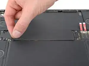
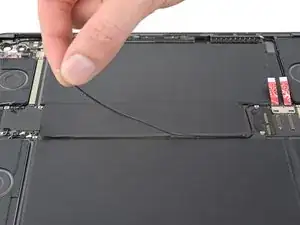
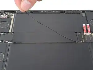
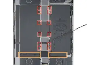
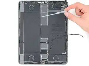
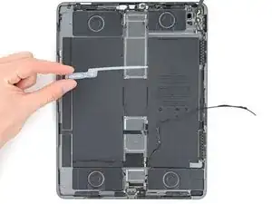
  14. 2mTQbC1mOkwXxcXw
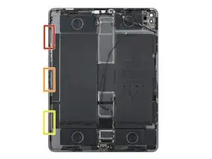
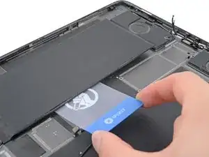
    • Along the left edge of the screen, there are three cutouts for cables where the adhesive is very thin. As you slice along this edge in the next step, don't insert your opening pick deeper than 2 mm in these locations:

    • The upper cutout begins 4 cm from the top edge and is 2.5 cm long.

    • The middle cutout is exactly in the middle of the frame and is 2.5 cm long.

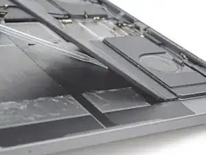
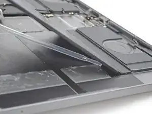
    • The lower cutout begins 4 cm from the bottom edge and is 2.5 cm long.

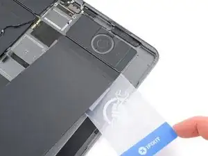
    • Everywhere else, don't insert your opening pick more than 5 mm.

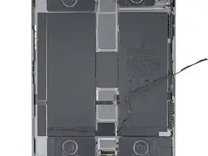
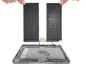
  15. 5OyIjg1GodfJD1IP
    5OyIjg1GodfJD1IP
    FeAMjuE5xOTpxXOA
    vDBOZxaNZ4kdVhRS
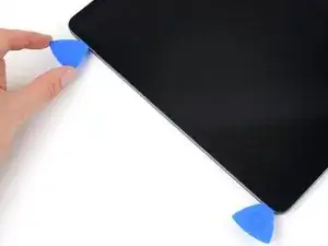
    • Insert a third opening pick in the bottom left corner of the screen.

    • Slide your pick to the top left corner to slice the left edge adhesive.

  16. ZSmIFBdEiCsOAUw6
    ZSmIFBdEiCsOAUw6
    t3O3yHay1c1aLxbh
    • Rotate your opening pick around the top left corner of the screen.

    • Leave your pick in the top left corner to prevent the adhesive from resealing.

  17. 5nCU2M6Q6FhObwcO
    • Apply a heated iOpener to the top edge of the screen for two minutes.

    • A hair dryer, heat gun, or hot plate may also be used, but be careful not to overheat the iPad—the screen and internal battery are susceptible to heat damage.

  18. CkmHZcDrKGEdTjYK
    CkmHZcDrKGEdTjYK
    SqULPLAADx3YLYmc
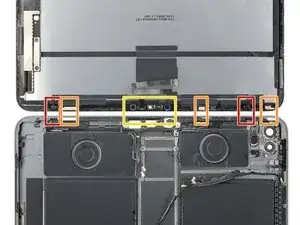
    • While the top edge adhesive softens, note the following:

    • There are two ambient light sensors near the corners. Only insert the very tip of your pick here to avoid damaging them.

    • There are three strips of heat dispersion tape. Angle your pick upward as you slice here.

    • The front-facing camera assembly is in the center of the top edge. Don't insert your pick here to avoid damaging them.

    • Everywhere else, don't insert your pick deeper than 5 mm to avoid damaging the screen.

  19. JQSUSVHpYUAWSMnt
    JQSUSVHpYUAWSMnt
    fuBqKciryhaCXtA2
    • Slide your opening pick 9 cm toward the center of the top edge to slice the adhesive, paying attention to the spots mentioned in the previous step.

    • If you slice farther than 9 cm, you will reach the front camera assembly and risk damaging its components.

    • Leave your pick inserted. You will use another pick to slice the remaining adhesive.

  20. LXUeQXbZu5IbxJaU
    LXUeQXbZu5IbxJaU
    gBiI5RHhiXvPDUKK
    • Insert a fourth opening pick to the right of the front camera assembly, 4 cm from the previous opening pick and 9 cm from the right edge of the screen.

    • Slide your pick to the top right corner to slice the remaining adhesive.

  21. WEn2BtDZMgAeTHS4
    WEn2BtDZMgAeTHS4
    Cwcongxk1qQcvna1
    uZNWeliRiWdDKi4N
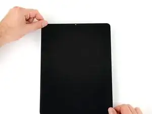
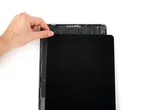
    • Grab two opposing corners of the screen and gently shift it around to separate it from the frame.

    • Don't fully remove the screen yet, as it's still attached by several cables.

    • If the screen feels stuck, slide your opening picks around the perimeter to separate any remaining adhesive. Pay attention to sensitive components mentioned in the previous steps.

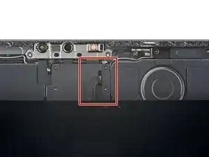
    • Shift the screen towards the bottom right corner of the frame until the ribbon cable near the top edge is uncovered.

  22. 4BDoClcCifNZNnHs
    • Throughout this guide, keep track of each screw and reinstall it exactly where it came from.

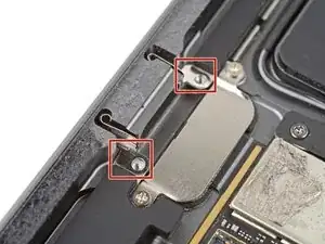
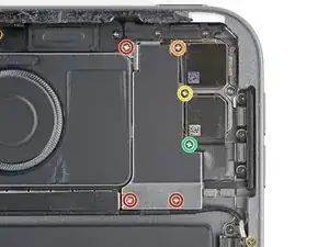
    • Use your Phillips screwdriver to remove the two screws securing the upper cable shield:

    • One 1.8 mm-long screw

    • One 2.0 mm-long screw

    • During reassembly, this is a good point to power on your iPad and test all functions before sealing it up. Be sure to power your iPad back down before you continue working.

  23. HJExQIpBLIHF6HOF
    HJExQIpBLIHF6HOF
    cATwmFhp6SEL3h5e
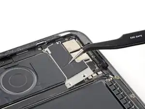
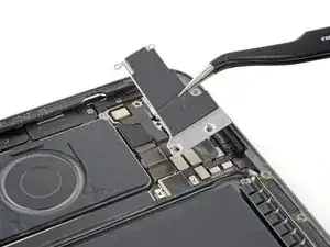
    • Use tweezers or your fingers to grab and remove the upper cable shield.

    • During reassembly, orient the shield so the notch faces up and to the right.

  24. oeUCs2KZqOUR1vdj
    oeUCs2KZqOUR1vdj
    INdyJvx44nBRNQtp
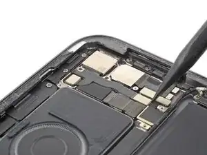
    • Use the point of your spudger to pry up and disconnect the upper sensors press connector.

    • To re-attach press connectors, carefully align and press down on one side until it clicks into place, then repeat on the other side. Don't press down on the middle. If the connector is misaligned, the pins can bend and cause permanent damage.

  25. uklmvYB5BTvRISmv
    uklmvYB5BTvRISmv
    VTvIfxQkVhyhjZF5
    rcsVVOjHTS6ZSUZx
    • Grip the right edge of the screen and fold it open like a book.

    • Don't pull on the screen—the ribbon cables near the bottom are still attached.

    • Lay the screen down over the left edge of the iPad.

  26. HBXpbTgXVNGSZ1PT
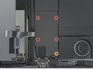
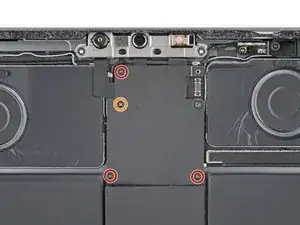
    • Use your Phillips screwdriver to remove the five screws securing the lower cable shield:

    • Four 1.1 mm screws

    • One 2.0 mm screw

  27. rE6IrLbtKLHP1sKd
    rE6IrLbtKLHP1sKd
    K6oZTbuN3hSUa5EQ
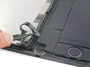
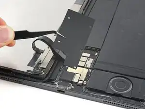
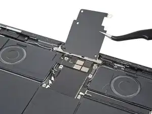
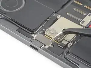
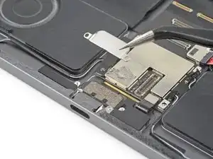
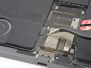
    • Use tweezers or your fingers to grab and remove the lower cable shield.

  28. xHyZtpdmjhvq5to2
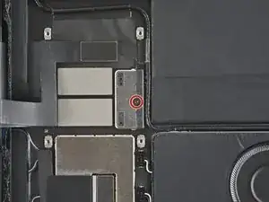
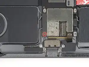
    • Use your Phillips screwdriver to remove the 1.7 mm screw securing the battery connector to the logic board.

  29. XuGcqDtLNfBI5uIL
    XuGcqDtLNfBI5uIL
    yneXEXnjID6lqfPN
    63PKMHpFYAXRZ2rO
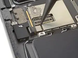
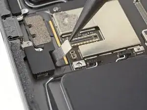
    • Use the point of your spudger to pry up and disconnect the upper two display press connectors from the logic board.

    What are these cards that got added? And what purpose do they serve?

    D Sully -

    In the past, we recommended blocking the battery connections with pieces of cards, but since revised our instructions to skip this. The pictures still show the cards in place, though. For your repair, you don't need to worry about them!

    Clay Eickemeyer -

  30. QaLWmpuX6Kd1lrL2
    QaLWmpuX6Kd1lrL2
    J6u6d5ICwgcOCjv6
    XrNkWosjDSAxSZkp
    • Use the point of your spudger to pry up and disconnect the lower two display press connectors from the logic board.

  31. lXWAoGtOWQe6jFiV
    lXWAoGtOWQe6jFiV
    jKpxnEY2FHZBT134
    • Grab and remove the screen from the frame.

  32. HPc4S5ArIjmYTptB
    HPc4S5ArIjmYTptB
    JMUsH4ClSRNtgXVP
    • Use the point of your spudger to pry up and disconnect the USB-C port press connector from the logic board.

  33. OGDogs3imR2akWBN
  34. QcWVCFog1OCiRBj2
    QcWVCFog1OCiRBj2
    hEBHywKMAp3pQRuI
    • Slide an opening pick under the USB-C port cable to separate it from the logic board.

  35. 5DObHQLj5xZFDrqQ
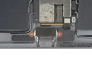
    • Use your Phillips screwdriver to remove the two 1.6 mm-long screws securing the USB-C port.

  36. p4ZbbLVlNoJIEZyU
    p4ZbbLVlNoJIEZyU
    M6GqjtfRfSHpM5Bm
    MeWi2ecTRWhcJMsh
    • Grab and remove the USB-C port from its recess in the frame.

    • Use caution not to lose the grounding contacts on either side of the USB-C recess.

    • During reassembly, install the USB-C port underneath the grounding contacts.

  37. YMNBOTypaM1mpyUT
    • Use your Phillips screwdriver to remove the four screws securing the upper cable shield:

    • Three 1.1 mm screws

    • One 2.0 mm screw

  38. xDuvw1tuuEkrSCUp
    xDuvw1tuuEkrSCUp
    RPKdXubwZljyQsNm
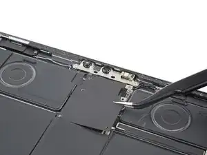
    • Use tweezers or your fingers to grab and remove the upper cable shield.

  39. UQrEhNiUFSPrkNBG
    UQrEhNiUFSPrkNBG
    UCYF3QX2sF36NWqh
    qZC6rha6bdfNqUTU
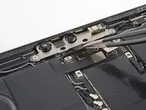
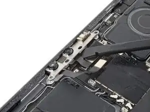
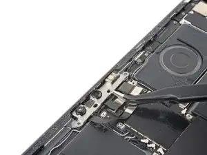
    • Use the point of your spudger to pry up and disconnect the three press connectors for the IR dot-projector, front camera, and Face ID camera.

  40. vjRT5rfBDxZYOF4L
    vjRT5rfBDxZYOF4L
    cKwI26FEOPrWBpZT
    mwRTmMM3NBGRaKKq
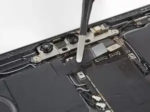
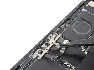
    • Use blunt nose tweezers to grab and peel the left and middle front camera assembly cables from the logic board.

  41. ChJ1TdUGFCCLCS2L
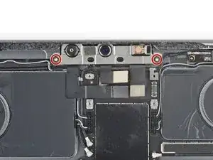
    • Use your T3 Torx screwdriver to remove the two 2.2 mm screws securing the front camera assembly bracket.

  42. VcyvVkSPVTFIMJ4Y
    VcyvVkSPVTFIMJ4Y
    pERUaFfgQAF1OoF1
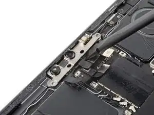
    • Use the flat end of your spudger to pry the front camera assembly bracket from its recess.

    • The bracket is secured by heat-resistant epoxy which requires significant force to weaken. Work slowly and avoid prying against the surrounding components.

  43. gIBBnU3MNhM42OEn
    gIBBnU3MNhM42OEn
    tsc4j4L5xNtipaZS
    RRAIVpcThLjw4V2A
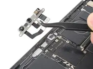
    • Use tweezers or your fingers to grab and remove the front camera assembly bracket from its recess.

    • Use a spudger to scrape and remove any residual epoxy before reinstalling the bracket.

  44. TOgSMrRVZMNHP1yf
    • Use your Phillips screwdriver to remove the six screws securing the rear camera shield:

    • Three 1.2 mm screws

    • One 2.8 mm screw

    • One 2.6 mm screw

    • One 1.8 mm screw

  45. 5cDEcJjG2EqGjgaH
    5cDEcJjG2EqGjgaH
    1rGidKOAYvrwnvoy
    • Use tweezers or your fingers to grab and remove the rear camera shield.

    • During reassembly, insert the tab on the left of the shield first.

  46. ItX5cWkMlLZniJX3
    ItX5cWkMlLZniJX3
    wHrNOOED1ARgxu4x
    COGyqZ1ntpcVwkJn
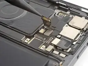
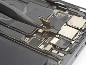
    • Use the point of your spudger to pry up and disconnect both of the power button's press connectors.

  47. RKMEpyp1gdhfYvKU
    • Use your Phillips screwdriver to remove the two 2.3 mm screws securing the power button assembly.

  48. vXSpNRJoQKlA4dVC
    vXSpNRJoQKlA4dVC
    Xe2wqkXIfQ1EBsNW
    M1lPxqMYl4L62cGB
    • Insert the point of your spudger between the left edge of the power button assembly and the frame.

    • Pry the assembly up from its recess in the frame.

    • Grab and remove the power button assembly.

    • Use a spudger to scrape and remove any residual epoxy before reinstalling the assembly.

  49. ScxUSrNCIOjJiJIk
    ScxUSrNCIOjJiJIk
    UkADx35lBfgWOSD3
    AeqZEJMEfJuwpLAu
    • Push the power button through its recess from the outside of the frame.

    • Remove the power button.

  50. eWIHhbrfbVYhChLl
    eWIHhbrfbVYhChLl
    KxxEVmkOHdrTiMmK
    • Use the point of your spudger to pry up and disconnect the wide-angle camera from the logic board.

  51. pokqfEyE1uorLCab
    pokqfEyE1uorLCab
    IoeQtXKRGJmcBQHM
    yqqkCIeSYjIQ1b5b
    • Use the point of your spudger to pry up and disconnect the LiDAR sensor and ultrawide camera from the logic board.

  52. XXIRj5eIZBiqCSwO
    XXIRj5eIZBiqCSwO
    byHrOGs2SgfEBJrp
    FoOOa2FXG2BKElXb
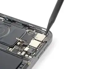
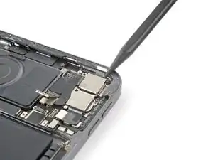
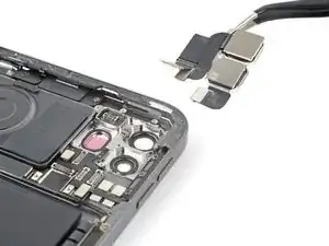
    • Insert the point of your spudger between the top right corner of the rear cameras and the frame.

    • Pry the cameras up until you can grab them with tweezers or your fingers.

    • Remove the rear cameras.

  53. WKDyvcLd5TGKmWds
    • Use your Phillips screwdriver to remove the two 1.9 mm screws securing the Smart Connector cover.

  54. UoFuZRPxSWlU5pRH
    UoFuZRPxSWlU5pRH
    LiiRsLKFMG6EtJWR
    • Use tweezers or your fingers to grab and remove the Smart Connector cover.

  55. aWKZgHQFgXLxyq4Z
    aWKZgHQFgXLxyq4Z
    wXi3PWSYDUkmrEMD
    • Use the point of your spudger to pry up and disconnect the Smart Connector from the bottom of the logic board.

  56. FeTeBRxGSUQAFPZE
    • Use your Phillips screwdriver to remove the 2.0 mm screw securing the lower left speaker cable shield.

  57. TPSaWswGSyVcIKRs
    TPSaWswGSyVcIKRs
    5WOw2Giv1NXfrhB5
    • Remove the lower left speaker cable shield.

  58. rBljcFkJOlgHQeaA
    rBljcFkJOlgHQeaA
    1yEFg2DNDnAyvIRC
    CydYSRhEUQQlHFnV
    • Use the point of your spudger to pry up and disconnect the lower speaker press connectors.

    • Avoid prying against the sides of the connectors. The sockets on the logic board are delicate and may bend if pried against.

    • Disconnect all four connectors for the lower speakers.

  59. MoG1s5eYZmyEvK5g
    MoG1s5eYZmyEvK5g
    ZYRAxaxoQFVGb1Yw
    yWPLXhJBhfPkHiih
    • Use the point of your spudger to pry up and disconnect all four upper speaker press connectors.

    • Avoid prying against the sides of the connectors. The sockets on the logic board are delicate and may bend if pried against.

  60. fVubOOVFyVHGnYQX
    fVubOOVFyVHGnYQX
    QVLSoNqY6I4gFULb
    Uxt1rdFsoKcWxxBZ
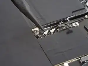
    • Use the point of your spudger to pry up and disconnect the upper antenna cable from the right edge of the logic board.

    • Pry on only the metal head of the connector. Avoid lifting the cable itself as much as possible.

  61. yXo3GeDUSoHENjLj
    yXo3GeDUSoHENjLj
    vRVZGZ24iKWZHAtP
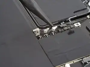
    • Use the point of your spudger to pry up and disconnect the lower antenna cable from the left edge of the logic board.

    • Pry on only the metal head of the connector. Avoid lifting the cable itself as much as possible.

  62. 16lXQ2OWQLbHHCaK
    16lXQ2OWQLbHHCaK
    VUIyaPmFJIPNoWRO
    dZrZGJPcdcY3WNTD
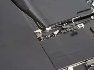
    • Use the point of your spudger to pry up and disconnect the remaining two antenna cables from the left edge of the logic board.

    • Pry on only the metal head of the connector. Avoid lifting the cable itself as much as possible.

  63. IJkpjqY4VytOKHAL
    IJkpjqY4VytOKHAL
    v1tujVtvAhMMVU3P
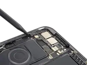
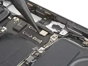
    • Use the point of your spudger to pry up and disconnect the upper sensor press connector from the logic board.

  64. Qcl4aABkOpDVdOv1
    Qcl4aABkOpDVdOv1
    wr6BoYcIRCbNLLwe
    • Use the point of your spudger to pry up and disconnect the rear sensor press connector from the right arm of the logic board.

  65. K6FfxHoU5d3nsCoW
    K6FfxHoU5d3nsCoW
    JnGCUNILAdR2eHQN
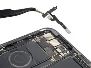
    • Use the point of your spudger to pry up and disconnect the volume press connector from the right arm of the logic board.

  66. nSBgiPiG2BWOirZt
    • Apply a heated iOpener to the upper antenna cable and right arm of the logic board for two minutes.

  67. QcxvUT4O42WStZtO
    QcxvUT4O42WStZtO
    tBBII5ZLnRbfwbJa
    TGVmcS2GKxGQX3eR
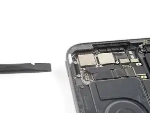
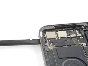
    • Use blunt nose tweezers or your fingernail to peel the tape securing the upper antenna cable to the right arm of the logic board.

    • Don't try to fully remove the cable—one more piece of tape secures it to the logic board.

    • If the tape feels stuck, pull the body of the cable with your fingers as you peel the tape.

  68. fanOiqEWCHDfKjao
    fanOiqEWCHDfKjao
    vfX2ojULwOOw3pgV
    yo1xcTT4ReNFJOIZ
    • Peel the second strip of tape securing the upper antenna cable to the logic board near the rear camera cutouts.

    • Reposition the cable away from the logic board.

    • Don't twist or rotate the antenna cable—it's still connected to the antenna.

  69. etsLHQWDLA6yIWaC
    • Apply a heated iOpener to the lower antenna cable, located along the left edge of the logic board, for two minutes.

  70. 2UZ3CJRWtLGXHXZs
    2UZ3CJRWtLGXHXZs
    CSKUJlZZYhnTBP36
    BwGTZFIBUnn1tlKQ
    • Grab the lower antenna cable, just below its metal connector head.

    • Peel the cable from the left edge of the logic board.

  71. x2BPcbYoMVGlblyA
    x2BPcbYoMVGlblyA
    b36pTHLYGISaMuAU
    y4sZpYtLwaeLkhOs
    • Peel the lower antenna cable from the logic board near the battery connector.

  72. iISsqN2v2xbWJJO2
  73. RKZO2DSRQZ36tLre
    RKZO2DSRQZ36tLre
    eQ6P4mKLg2FQdDDk
    aWFF4MCJwkwNMjrS
    • Use your fingers to grab a corner of the logic board cover.

    • Peel and remove the cover from the logic board.

    • Work slowly to avoid tearing the cover.

    • The cover has many layers. Make sure the copper tape doesn't separate from the foam layer.

  74. SUpsmU16OEddOZey
    SUpsmU16OEddOZey
    PriUQ2SIctZNTJYZ
    TgVCUJaILJCGCKiB
    • Use the flat end of your spudger to slide the bottom right press connector bracket away from the logic board.

    • Use blunt nose tweezers or your fingers to remove the bracket.

    • During reassembly, orient the bracket so the outward-bent wings face the battery.

  75. Owj6YJRpm2jNgbxg
    Owj6YJRpm2jNgbxg
    E1RYZPCJsxOx3jGB
    XLwBiXfWcELMYeTA
    • Use the point of your spudger to pry up and disconnect the microphone and Apple Pencil charger press connectors.

  76. PnFKOXvcUfafKRCl
    • Use your Phillips screwdriver to remove the four 1.8 mm screws securing the logic board.

  77. n2f24hiTyXRDZroG
    n2f24hiTyXRDZroG
    3h1JwUSNdBQLItNw
    6EWXM1XtKQD5gZAN
    • Apply several drops of highly-concentrated isopropyl alcohol (over 90%) to the bottom and right edges of the logic board.

    • Elevate the right edge of the iPad to allow the isopropyl alcohol to flow under the logic board.

    • Wait one minute for the isopropyl alcohol to penetrate.

  78. lwwVXNQXfpZU3vdQ
    lwwVXNQXfpZU3vdQ
    5ICSikxqdK3dgGd3
    yuRODF2TgIJDX1KB
    • Apply isopropyl alcohol to the right arm and left edge of the logic board.

    • Elevate the left edge of the iPad to allow the isopropyl alcohol to flow under the logic board.

    • Wait one minute for the isopropyl alcohol to penetrate.

  79. QoyoSLOk6BkjHX2C
    QoyoSLOk6BkjHX2C
    IASOIEH2jOIoQdVl
    • Insert an opening pick between the bottom edge of the logic board and the Smart Connector.

  80. HuI3dY1ExmtD2qXt
    HuI3dY1ExmtD2qXt
    iNCHUQEoEUlqUdjx
    1ZborEinkxqA2OIv
    • Remove the card strips blocking the battery connector.

    • Gently insert the tip of an opening pick between the logic board and the battery connector.

    • Don't pry on the battery connector or logic board, as the spring connectors are easily damaged.

    • Leave this pick inserted until the logic board is completely removed.

  81. 2aP1fNurOEp4uYXg
    2aP1fNurOEp4uYXg
    PxyyByYHBvoNxqDn
    jbWyhalxOmoQXpiC
    • Use the first opening pick to pry up the left edge of the logic board.

    • Don't forcefully lever against the battery—a punctured or bent battery may leak dangerous chemicals or cause a fire.

    • If the logic board feels stuck, apply more isopropyl alcohol.

  82. WHHkcZZlmVPlRDVP
    WHHkcZZlmVPlRDVP
    VTwQP2tqV3hukAMO
    • Use your opening pick to pry up the right arm of the logic board.

    • This arm of the logic board is thin and fragile. Be careful not to bend it.

  83. q3pHajULDNFlDLJS
    q3pHajULDNFlDLJS
    lgCoUTZKcBXeQvBp
    • Use your opening pick to pry up the right edge of the logic board.

    • Don't forcefully lever against the battery—a punctured or bent battery may leak dangerous chemicals or cause a fire.

    • If the logic board feels stuck, apply more isopropyl alcohol.

  84. TeGQsDNTkfKBYcPT
    TeGQsDNTkfKBYcPT
    OwiEOdZJCQITQuPa
    • Grab and remove the logic board from the frame.

    • Be careful not to reinstall the logic board on top of any cables or connectors.

    • During reassembly, apply double-sided tape such as Tesa tape to secure the logic board if the existing adhesive isn't sufficient.

  85. 2KGByVELTSxoXNVU
    2KGByVELTSxoXNVU
    VDQhOiM4RCDXEuYJ
    • There are twelve stretch-release adhesive pull tabs securing the batteries to the frame.

    • The remaining adhesive secures the battery boards to the bottom of the frame, and has no stretch-release tabs.

  86. cSZvxUK5L1Aqcbud
    cSZvxUK5L1Aqcbud
    UCAZHXygAIs4eJif
    56VTewD6xvIObTXE
    • Use blunt nose tweezers or your fingers to peel each stretch-release pull tab away from the battery.

    • Slowly pull the strips straight away from the battery, keeping a low angle to the frame.

    • Give the strips plenty of time to stretch. If a strip breaks off, try to retrieve it and continue pulling.

    • If you removed all 12 stretch-release adhesive strips, skip down three steps.

    • If any strips broke off, follow the next two steps for an alternative method to remove the battery.

  87. mQSROEsyuBICkWsR
    mQSROEsyuBICkWsR
    HHKf2D1IOTiLg1wN
    BCZkApOIhOwDrWEX
    • This step shows how to soften any stretch-release adhesives that broke off in the previous step.

    • Apply several drops of highly-concentrated isopropyl alcohol (over 90%) to the inside edges of the batteries near any broken strips of stretch-release adhesive.

    • Elevate each edge of the iPad to allow the isopropyl alcohol to flow under the batteries.

    • Wait one minute for the isopropyl alcohol to penetrate.

  88. cZcPb1URYHmnPwgr
    cZcPb1URYHmnPwgr
    3UPFFZseFhPnEuOy
    GB6otxb63T2pqgZO
    • Slide a plastic card under the left battery near any broken strips of stretch-release adhesive.

    • Slide the plastic card along the length of the battery to separate any remaining adhesive. Don't slide your card underneath the battery boards.

    • Don't puncture or bend the battery. If it feels stuck, apply more isopropyl alcohol or apply a heated iOpener to the back of the frame.

    • Repeat this step for the right battery.

  89. sAG4xuh5iv3hDo4D
    sAG4xuh5iv3hDo4D
    pEMgkXnvFLb1SyZv
    • Elevate the top edge of the iPad and raise the left battery to allow access underneath the battery board.

    • Don't raise the battery more than 45 degrees.

    • Apply a few drops of isopropyl alcohol to the battery board.

    • Repeat this step for the right battery.

  90. 1g1iuYHxetQEuZ4C
    1g1iuYHxetQEuZ4C
    epwnbvhmJCOxYNew
    YYOAQSAWFLpjIkQd
    • Lay your iPad flat and slide your plastic card at a slight angle under the outer edge of the left battery board.

    • Straighten the plastic card and fully insert it under the battery board to slice the adhesive.

    • Repeat this step for the right battery.

  91. Y1MorAOWGHRQJaKf
    Y1MorAOWGHRQJaKf
    KeRBTj5qBxelqAux
    fhOxIJTiGF5FmHGY
    • Grab both halves of the battery by the upper corners and remove them from the frame.

    • Be careful not to twist or pull the cable connecting the halves of the battery.

    • Clean any remaining adhesive with a few drops of isopropyl alcohol and a lint-free cloth.

    • Don't reuse your old battery. A damaged or deformed battery is a safety hazard.

    • During reassembly, apply double-sided tape such as Tesa tape under the new battery.

Conclusion

Compare your new replacement battery to the original one—you may need to transfer remaining components or remove adhesive backings from the new battery before installing.

To reassemble your device, follow these instructions in reverse order.

Take your e-waste to an R2 or e-Stewards certified recycler.

Repair didn’t go as planned? Try some basic troubleshooting, or ask our iPad Pro 12.9" 4th Gen Answers community for help.

Clay Eickemeyer

Member since: 19/09/22

65190 Reputation

2 comments

Is there a way to test the battery with a multimeter before removing all the components?

(Mine is unresponsive and I’m trying to trouble shoot components)

D Sully -

Hey D Sully,

Apple definitely hid a lot of the exposed contacts in this iPad. To reach the contacts on the battery connector, you need to get underneath the connector on the logic board.

There could still be ways to troubleshoot your iPad without opening it. If you haven't already, try force restarting it, plugging it into power for over a minute, trying a different charger, etc. If you do opt to open it, check the screen connectors, as well.

If the probes on your multimeter are sufficiently small, you might be able to remove just the lower components from the logic board (including the four screws securing it to the frame) and slightly lift it to gain access to the battery contacts. We don't recommend this as, it risks damaging the board.

Whatever routes you choose, good luck and feel free to post back here with any results!
Clay Eickemeyer -