
Introduction
Use this guide to replace the screen (aka display) on your Steam Deck LCD. The procedure is the same for both standard and anti-glare etched glass screens.
Remember: follow general electrostatic discharge (ESD) safety procedures while repairing your device.
Note: If you're installing a 512 GB model display onto a 64 / 256 GB device or vice versa, you'll need to ensure that a matching display flex cable is installed as well. Both types of displays come with their specific flex cables.
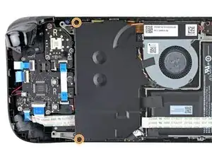
Note: Valve started shipping Steam Decks with refreshed internal designs in early 2023. Your Steam Deck may look different than the one depicted in the photos, but the procedures are very similar. Remove the back cover to check what version you have. An original Steam Deck will have a metallic motherboard shield and a fan with square sides, as seen here. A refreshed Steam Deck will have a black motherboard shield and a fan with curved sides, as seen here.
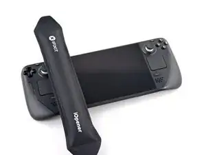
Tools
-
-
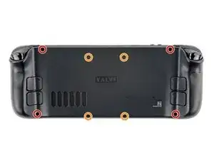
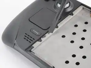
Use a Phillips driver to remove the eight screws securing the back cover:
-
Four coarse thread 9.5 mm-long screws
-
Four fine thread 5.8 mm-long screws
-
-
-
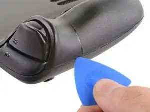
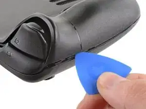
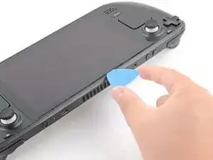
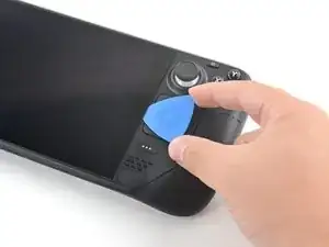
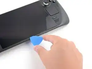
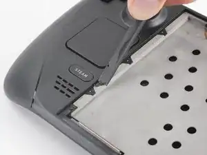
Insert an opening pick into the thin gap between the back cover and the front shell, along the edge of the right grip.
-
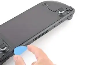
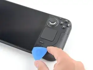
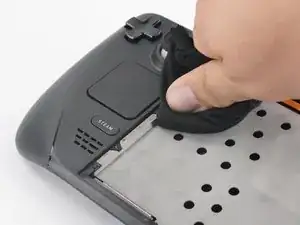
Pry up on the back cover to release it from the locking clips.
-
-
-
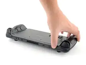
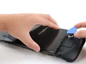
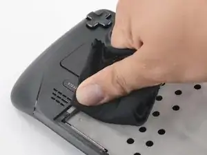
Grip the back cover at the opening you just created and pull it up and away from the device to unclip the long edges.
-
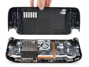
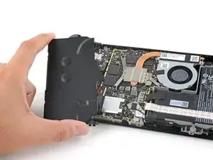
Remove the back cover.
-
-
-
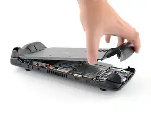
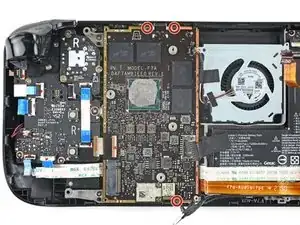
Use a pair of tweezers to remove the piece of foil tape covering the hidden screw on the board shield.
-
-
-
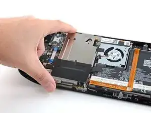
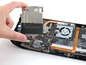
Use a Phillips driver to remove the three screws securing the board shield:
-
One 3.4 mm screw
-
Two 3.7 mm screws
-
-
-
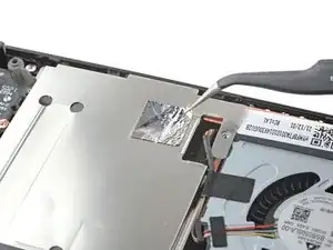
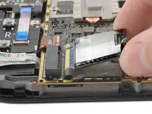
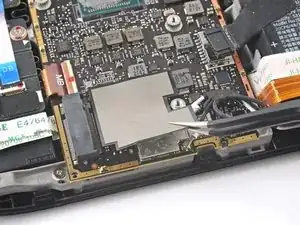
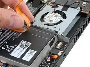
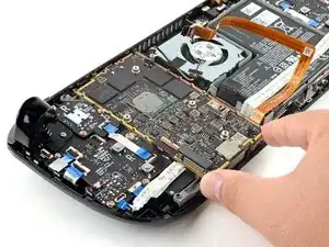
Grip the battery cable by its pull tab and pull it directly away from the motherboard to disconnect it.
-
-
-
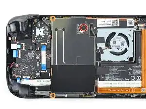
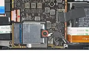
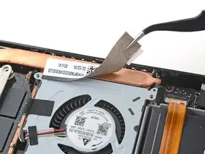
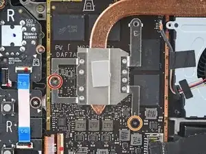
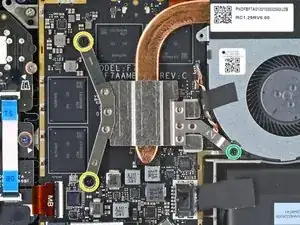
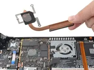
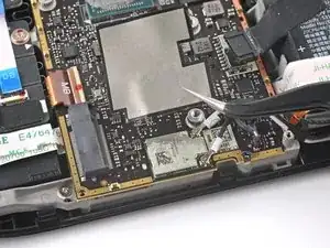
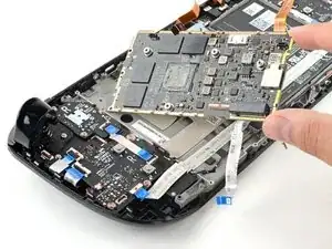
For original Steam Decks: Use a Phillips driver to loosen and remove the two screws securing the heatsink to the motherboard:
-
One captive 3.5 mm screw
-
One 3.4 mm screw
-
For refreshed Steam Decks: Use a Phillips driver to remove the three screws securing the heatsink to the motherboard:
-
Two 2.9 mm screws
-
One 3.7 mm screw
-
-
-
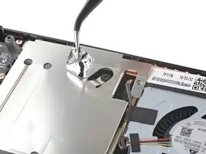
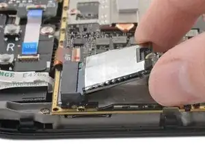
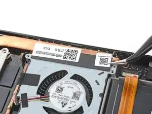
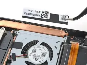
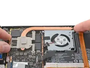
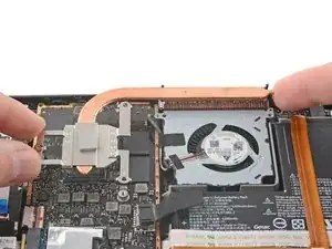
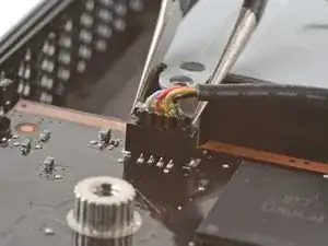
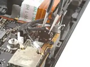
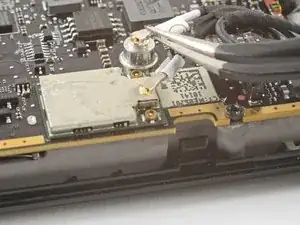
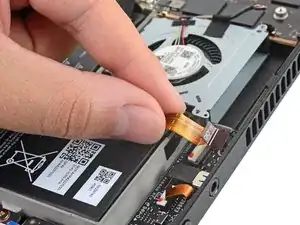
Use a pair of tweezers to grip the edges of the fan connector and pull up to disconnect it from the motherboard.
-
-
-
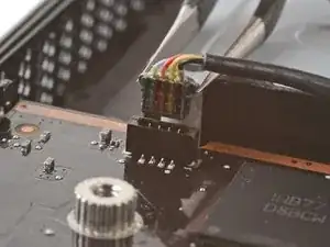
Use a pair of tweezers to grip the edges of the speaker connector and pull up to disconnect it from the motherboard.
-
-
-
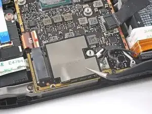
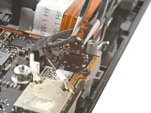
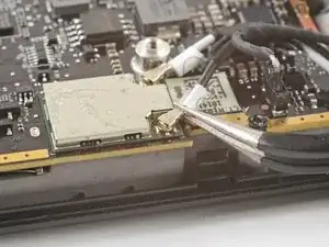
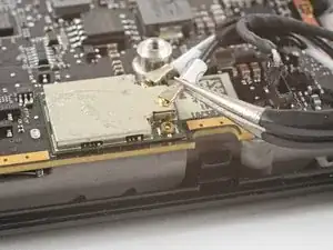
Use a pair of tweezers to grip the antenna connector close to its base.
-
Pull straight up to disconnect the cable.
-
Repeat for the second antenna cable.
-
-
-
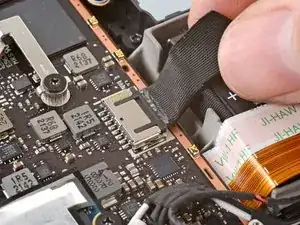
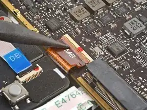
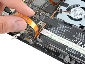
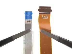
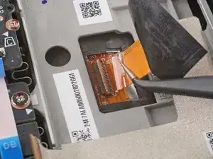
Use the pointed end of a spudger to lift up the small locking flap on the display cable's ZIF connector.
-
Use a pair of tweezers to slide the cable out of its connector.
-
-
-
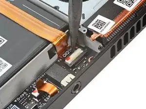
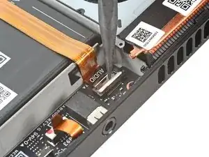
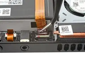
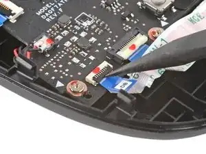
Use the pointed end of a spudger to lift up the small locking flap on the audio cable's ZIF connector.
-
-
-
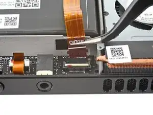
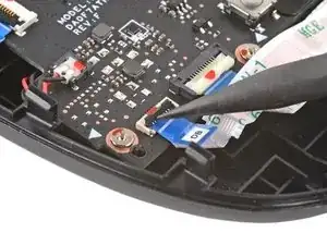
Use the pointed end of a spudger to lift up the small locking flap on the button board cable's ZIF connector.
-
Use a pair of tweezers to slide the cable out of its connector.
-
-
-
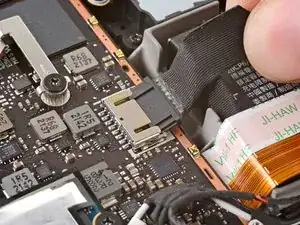
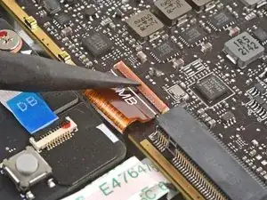
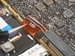
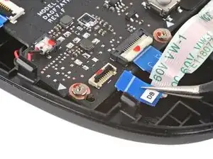
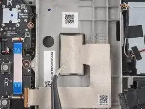
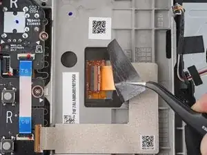
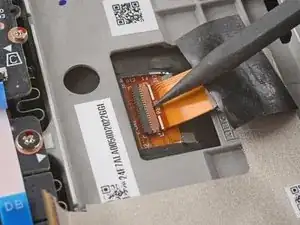
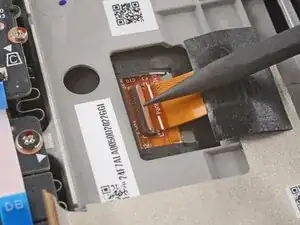
Use the pointed end of a spudger to lift up the small locking flap on the display cable's ZIF connector.
-
Use a pair of tweezers to slide the cable out of its connector.
-
-
-
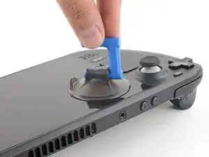
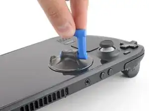
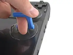
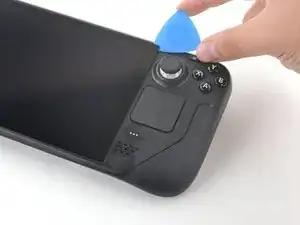
Apply a suction cup to the top left corner of the display by pressing down on it to create suction, as close to the edge as possible.
-
-
-
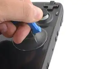
Pull up on the suction cup with strong, steady force to create a gap between the display and the frame.
-
Insert the point of an opening pick into the gap.
-
-
-
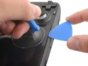
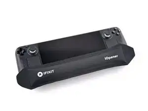
Heat the left edge of the display for one minute.
-
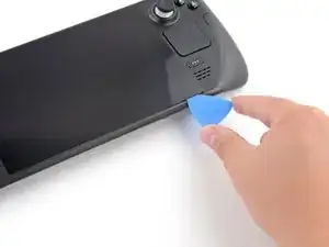
Slide the opening pick across the left edge to slice the adhesive.
-
-
-
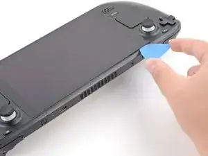
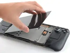
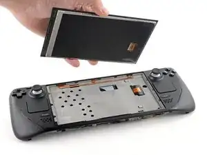
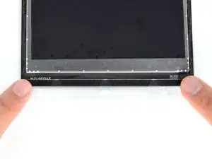
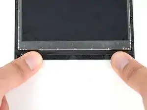
Once you have sliced around the perimeter of the display, carefully lift the right edge up, opening it like a book.
-
Remove the display.
-
-
-
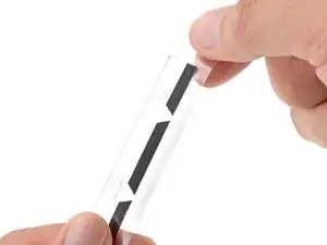
Look over the new display adhesive and match each strip to its respective side of the display.
-
-
-
Use adhesive remover or isopropyl alcohol (>90%) to remove any remaining residue. Wipe in one direction with a lint-free cloth or coffee filter until all the adhesive residue is gone.
-
Allow any leftover isopropyl alcohol to completely evaporate before reassembly.
-
-
-
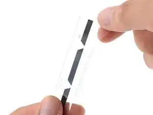
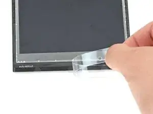
Once you have a good idea of where the adhesive strip goes, peel off and discard the liner, exposing the adhesive underneath.
-
-
-
Set the adhesive onto the surface and press firmly with your fingers to set it in place.
-
Repeat the previous two steps for the three other display adhesive strips.
-
-
-
Peel off and discard the remaining plastic liners on all four strips, exposing the adhesive underneath.
-
Repeat for all four display adhesive strips, being careful not to touch any exposed adhesives.
-
-
-
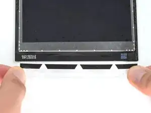
Set the new display in place on the midframe and press firmly along the edges for 20-30 seconds to ensure a good adhesive bond.
-

To reassemble your device, follow these instructions in reverse order.
Take your e-waste to an R2 or e-Stewards certified recycler.
Repair didn’t go as planned? Try some basic troubleshooting, or ask our Steam Deck answers community for help.

22 comments
Attempted this tonight after smashing the screen on my deck. Easy to follow and worked flawlessly first time. Thank you
On peut mettre un autre ecran OLED ou autre ?
Non. Le matériel ne prend en charge qu'un écran très similaire ou identique à l'original.
Forge -
This guide is gold standard. Not once did I think “why didn’t they mention this?”
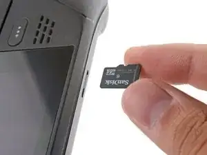
there should be a picture of the SD card slot at the start of every Steam Deck teardown. i know the note is there but i generally use the pictures to guide me and forgetting to remove the SD card is a very critical step
Nathan Barrow -
I agree, I just broke mine...
Camille B -
What is the the #1 philips used for? Only the #0 is mentioned in the instructions.
Christopher Martin -
I wish they would specify which size to use for which screws.
Mark D -
I found it easiest to use a PH1 for the red screws, and PH0 for the rest (including the internals.)
Chris Clawson -
Be careful you can strip the screws take your time
I use PH00 bit
jaybush74 -
I used the PH1 bit for this. You can use smaller bits but ideally there should be no play of the bit in the screw head.
Charles Semple -
are there playstation replacements (circle,square,cross,triangle)
Deór -
I used the ifixit tools and used the 00 size for the screws on the back.
Luis B -
I've completed the guide and found it very helpful!
I think somewhere in this part it would be helpful to name the size of the correct Phillips driver to use:
Maynard -
I used the PH1 for the 9.5mm screws and PH00 for the 5.8mm screws. The PH0 wanted to strip one of the small ones.
Pol Llovet -
FYI - 512gb version has blue threadlocker on the Orange screws.
Kyle -
Just a point for knowledge sake, the Four 5.8mm screws on this step are factory installed with a version of locktite. Not sure why but there will be slight resistance when removing the first time.
Derek Schmidlin -
Stripped two of the 5.8mm screws, feel pretty dumb, now I'm stuck at step 2 of 43 :|
Yareyous -