
Introduction
Tools
-
-
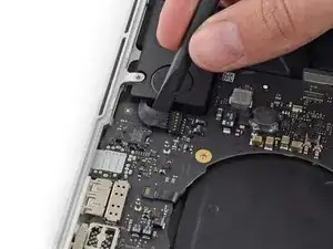
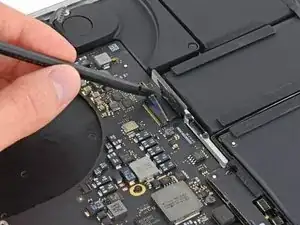
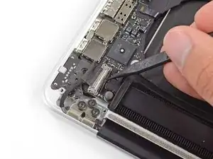
Use the flat end of a spudger to pry the left speaker connector up and out of its socket on the logic board.
-
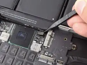
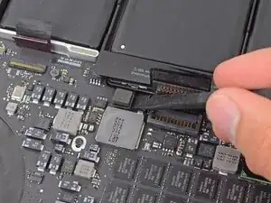
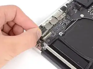
Use the tip of a spudger to pry the right speaker connector up and out of its socket on the logic board
-
-
-
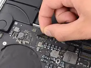
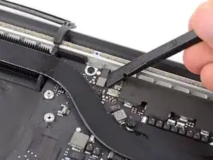
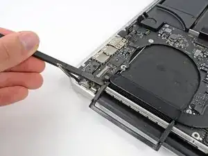
Peel back the tape covering the top of the keyboard ribbon cable connector.
-
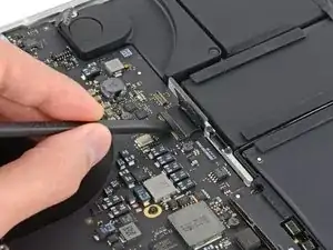
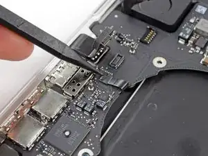
Use the flat end of a spudger to flip up the retaining flap on the keyboard ribbon cable ZIF socket.
-
Use the flat end of a spudger to push the keyboard ribbon cable out of its socket.
-
-
-
Use the flat end of a spudger to pry the trackpad ribbon cable connector up out of its socket.
-
-
-
Use the flat end of a spudger to pry the keyboard backlight connector up from its socket on the logic board.
-
-
-
Use the tip of a spudger or your fingernail to flip up the retaining flap on the microphone ribbon cable ZIF socket.
-
Pull the microphone ribbon cable out of its socket.
-
-
-
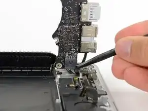
Use the tip of a spudger to flip up the display data cable lock and rotate it toward the DC-In side of the computer.
-
Pull the display data cable straight out of its socket on the logic board.
-
-
-
Use the flat end of a spudger to carefully pry off the rubber screw cap on the raised screw head near the MagSafe 2 connector.
-
-
-
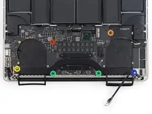
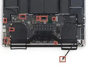
Remove the following six screws securing the logic board to to the upper case:
-
One 3.1 mm T5 Torx screw
-
One 2.5 mm T5 Torx screw
-
One 5.5 mm silver, raised-head T5 Torx screw
-
Two 5.7 mm T5 Torx screws
-
One 3.8 mm silver T5 Torx screw
-
-
-
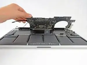
Lifting from the side nearest the battery, rotate the logic board toward the top of the MacBook Pro.
-
Using the flat end of a spudger, carefully push the MagSafe 2 connector out of its socket on the bottom of the logic board.
-
-
-
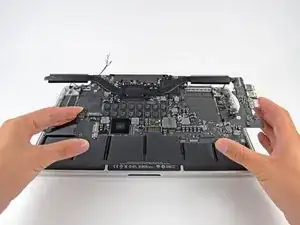
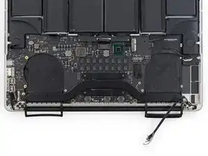
Remove the logic board assembly from the MacBook Pro.
-
Second photo, clockwise from top: battery, right speaker, keyboard backlight, AirPort/camera, display, microphone, left speaker, keyboard, and trackpad.
-
To reassemble your device, follow these instructions in reverse order.
At this point, it should be noted that the author is using two different logic boards through the procedure. Here, for the first time is the difference between a 2.3 GHz board and the 2.6 GHz board. The audio out socket is integral to the 2.3 GHz board. The 2.6 GHz board has a discrete audio out jack that plugs into the logic board. As the disassembly proceeds, the 2.6 board’s audio outlet is unplugged (Step 26/27 pictures note this, but the author doesn’t. So, as I hoped, the 2.3 GHz board can be replaced by a 2.6 GHz board, IF you don’t want an audio out jack!
David White -