Introduction
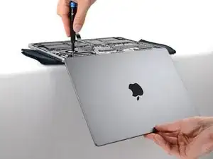
Use this guide to replace a broken screen on your MacBook Pro 14" Late 2023 (M3).
WARNING: While you can physically replace the screen by following this guide, replacement screens are known to display visual artifacts. Currently, the only available fix is Apple's System Configuration tool (which is only available through Apple when purchasing a genuine replacement screen). Alternatively, two soldered chips can be transferred between the screen controller boards.
If your battery is swollen, take appropriate precautions and consider replacing your battery.
Tools
-
-
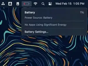
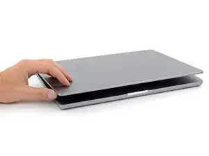
Fully shut down your MacBook, close the lid, and flip it over. Keep the lid closed until you've physically disconnected the battery.
-
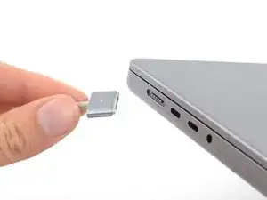
Unplug the MagSafe cable and any accessories connected to your MacBook.
-
-
-
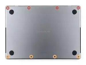
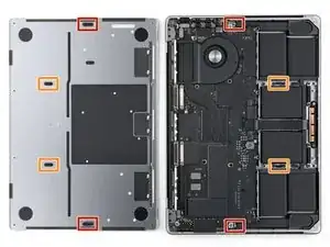
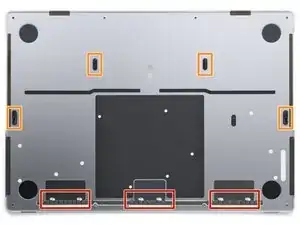
Use a P5 pentalobe driver to remove the eight screws securing the lower case:
-
Four 9.2 mm-long screws along the back edge (near the screen hinge)
-
Four 5 mm-long screws along the front edge (near the trackpad)
-
-
-
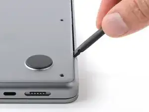
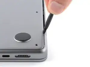
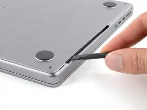
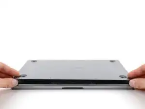
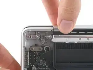
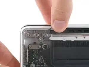
Insert the flat end of a spudger between the lower case and the right screen hinge.
-
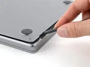
Lever your spudger against the hinge to push the lower case away from it.
-
Repeat for the left hinge.
-
-
-
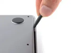
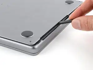
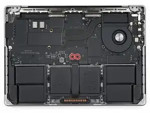
Insert the flat end of your spudger into the front of the cutout in the right side of the frame.
-
Slide your spudger toward the back of the cutout and pry up to release the two right-side clips.
-
Repeat for the left-side speaker cutout to release the two left-side clips.
-
-
-
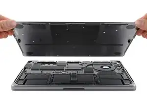
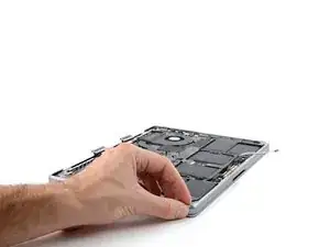
Remove the lower case.
-
Lay it down and align the sliding clips with the back edge of the MacBook. Press down on the lower case and slide it toward the back edge to engage the clips.
-
Once the back corners of the lower case are secured and flush with the frame, press down along the middle of the lower case to engage the four remaining clips.
-
-
-
Use a T3 Torx driver to remove the two 2.1 mm-long 3IP Torx Plus screws securing the trackpad connector cover.
-
-
-
Use the flat end of your spudger to pry up and disconnect the trackpad press connector from the logic board.
-
-
-
Peel the trackpad cable from the battery board and move it over the front edge of the MacBook.
-
-
-
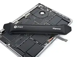
The battery data cable is adhered to the battery board and logic board. In the next few steps, you'll disconnect it, separate its adhesive, and remove it.
-
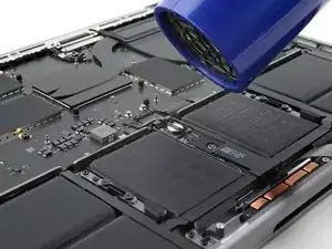
Heat an iOpener and place it on the battery data cable for 30 seconds to soften its adhesive.
-
-
-
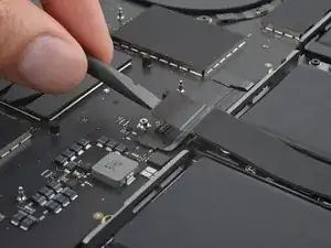
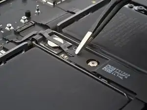
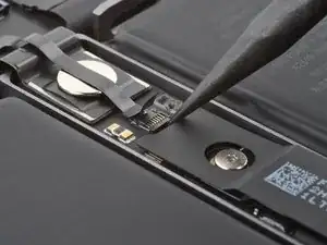
Use your tweezers to peel back the tape covering the battery data cable ZIF connector on the battery board.
-
-
-
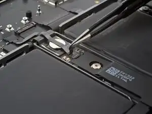
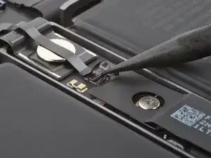
Use the point of your spudger to flip up the small locking flap on the battery data cable ZIF connector on the battery board.
-
-
-
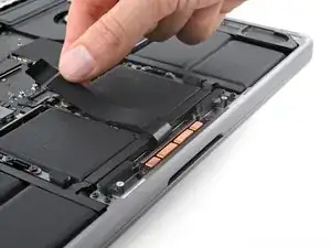
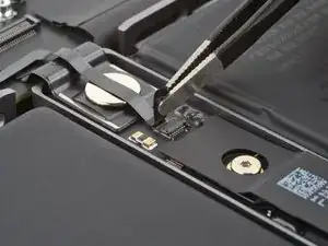
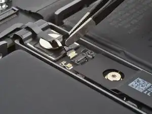
Use your tweezers to slide the connector straight out of its socket to disconnect it from the battery board.
-
-
-
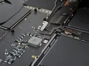
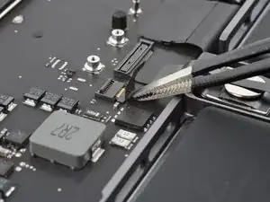
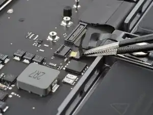
Use your tweezers to peel back the tape covering the battery data cable ZIF connector on the logic board.
-
-
-
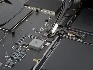
Use the point of your spudger to flip up the small locking flap on the logic board battery data ZIF connector.
-
-
-
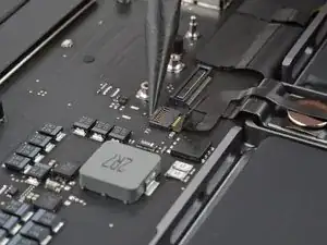
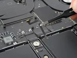
Use your tweezers to grip the neck of the cable and slide it straight out of its socket to disconnect it from the logic board.
-
-
-
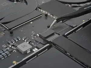
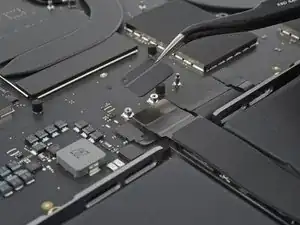
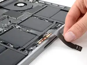
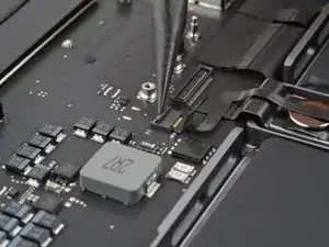
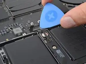
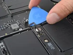
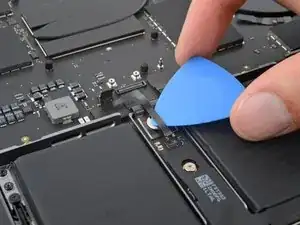
Slide the tip of an opening pick between the upper section of the battery data cable and the logic board to separate the adhesive.
-
Slide your pick between the lower section of the cable and the silver wide-head screw to separate the remaining adhesive.
-
-
-
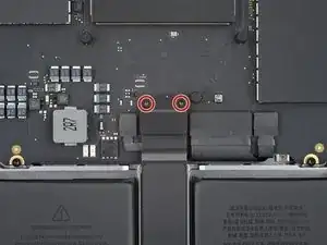
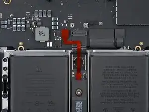
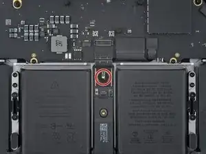
Use a T5 Torx driver to remove the 3.9 mm-long 5IP Torx Plus wide-head screw securing the main battery connector.
-
-
-
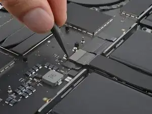
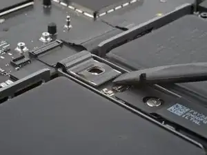
Use the flat end of your spudger to lift the main battery connector away from the battery board, disconnecting the battery.
-
For added safety, place a non-conductive barrier, such as a piece of a playing card, between the connector and board.
-
-
-
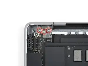
Use your T3 Torx driver to remove the three 2.1 mm-long 3IP Torx Plus screws securing the antenna connector cover and bracket.
-
Remove the cover.
-
-
-
Insert one arm of your angled tweezers under the metal neck of one of the antenna connectors and gently lift up to disconnect it.
-
Repeat for the other two antenna connectors.
-
-
-
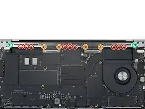
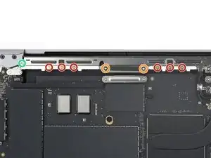
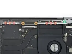
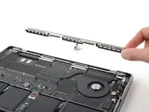
Use a P2 pentalobe driver to remove the nine 1.6 mm-long screws securing the antenna bar.
-
Use your T5 Torx driver to remove the six remaining 5IP Torx Plus screws securing the antenna bar:
-
Four 3.2 mm-long screws
-
Two 7.5 mm-long screws
-
-
-
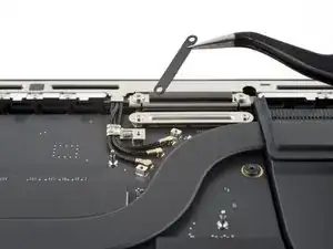
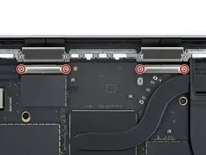
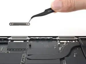
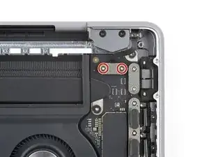
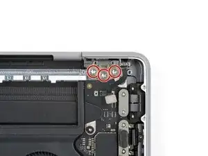
Use your T3 Torx driver to remove the four 2.1 mm-long 3IP Torx Plus screws securing both screen connector covers.
-
-
-
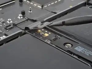
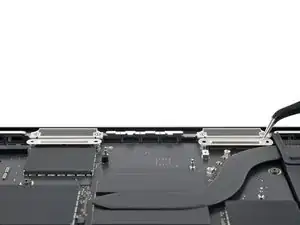
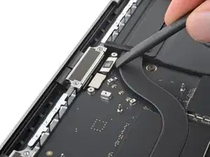
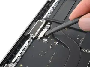
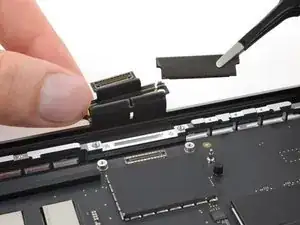
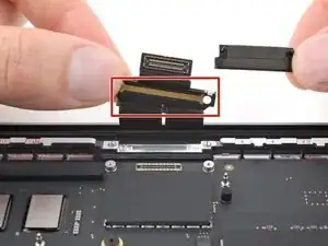
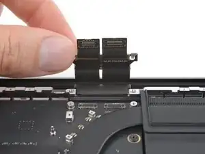
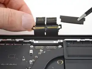
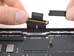
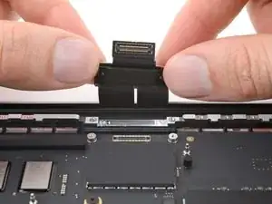
Use the flat end of your spudger to pry up and disconnect the three screen press connectors.
-
-
-
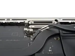
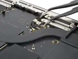
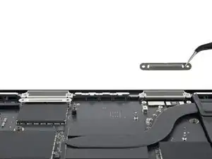
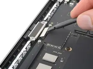
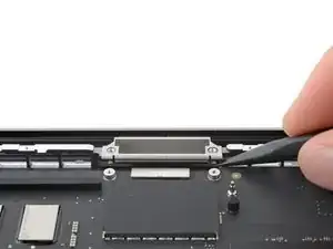
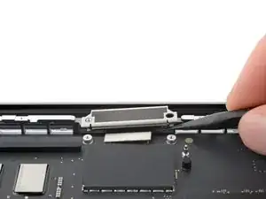
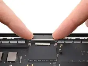
Use the point of your spudger to pry up the small metal tab on the left screen-cable bracket to unclip it from the frame.
-
Grab the bracket and lift the cables out of their recess in the frame.
-
-
-
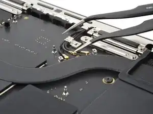
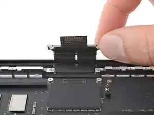
Remove the left cable buffer from the frame.
-
The cable buffer might stay stuck in the metal bracket. If so, remove it from the bracket.
-
-
-
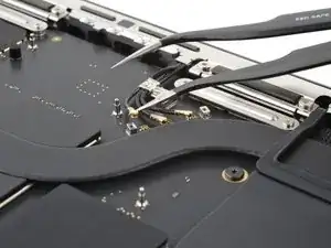
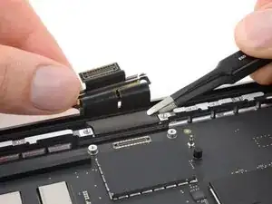
Pry up and free the right screen-cable bracket from the frame, just as you did with the left cables.
-
Remove the cable buffer.
-
-
-
Insert the cable buffer into the metal bracket with the buffer's alignment pegs pointing toward the MacBook and closest to the cable's press connector.
-
Align the cable buffer's pegs with its holes in the frame.
-
Press the cable bracket onto the frame, so its metal tabs clip into place.
-
-
-
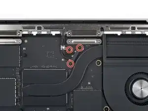
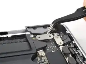
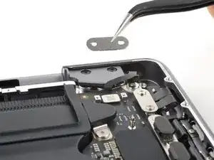
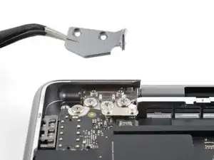
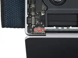
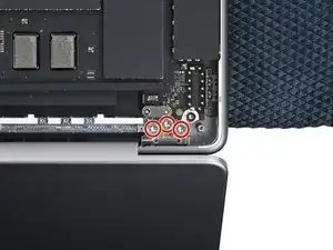
Use your T3 Torx driver to remove the two 2.1 mm-long 3IP Torx Plus screws securing the lid angle sensor connector cover.
-
Remove the cover.
-
-
-
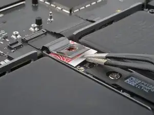
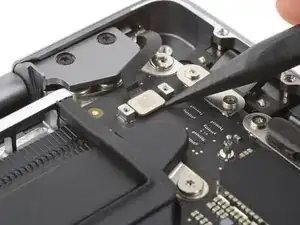
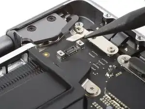
Use the point of your spudger to pry up and disconnect the lid angle sensor press connector.
-
-
-
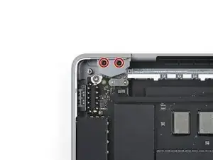
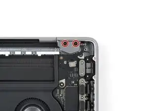
Use your T5 Torx driver to remove the two 2.5 mm‑long 5IP Torx Plus screws securing each hinge cover (four screws in total).
-
-
-
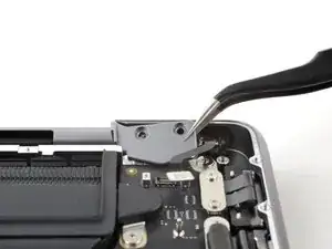
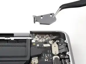
Use tweezers or your fingers to slide each hinge cover away from the back edge and lift straight up to remove them.
-
-
-
Use a T8 Torx driver to slightly loosen the six 8IP Torx Plus screws securing the screen hinges.
-
-
-
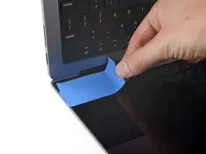
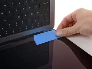
If you plan on reusing your screen, apply a couple strips of tape to the lower corners of it to prevent scratches from the frame during removal.
-
-
-
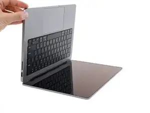
Place a soft cloth on the edge of a table or your work surface.
-
Lay your MacBook keyboard-side down on the edge of your work surface with the screen hanging straight down.
-
-
-
Keep the main body secured against your work surface and open the screen as far as it will go.
-
-
-
Use your T8 Torx driver to remove the six 5.2 mm-long 8IP Torx Plus screws securing the screen hinges.
-
-
-
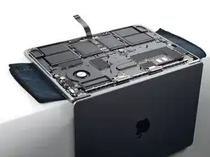
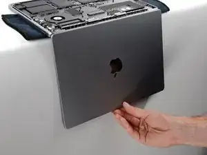
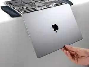
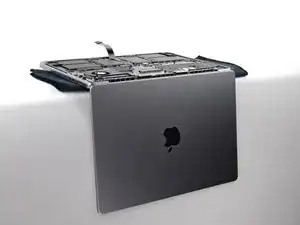
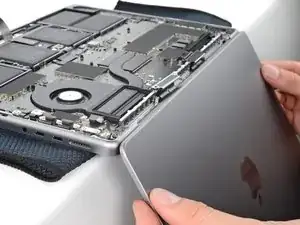
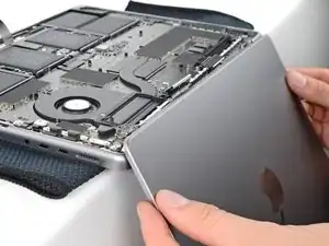
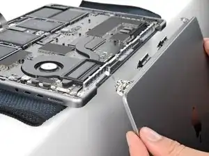
Lift the left hinge up and out of its recess in the frame.
-
Repeat for the right hinge.
-
Remove the screen.
-
-
-
Install the hinge screws without fully tightening them. Center the hinges and check for gaps or rubbing on either side.
-
Fully tighten the hinge screws.
-
If your screen clicks or snaps when it's opened or closed, loosen the screws and realign the screen.
-

To reassemble your device, follow these instructions in reverse order.
Take your e-waste to an R2 or e-Stewards certified recycler.
Repair didn’t go as planned? Try some basic troubleshooting, or ask our Answers community for help.