Introduction

This repair guide was authored by the iFixit staff and hasn’t been endorsed by Google. Learn more about our repair guides here.

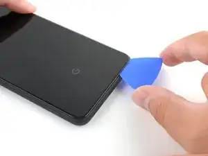
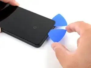
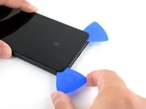
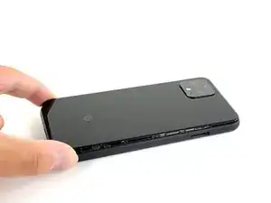
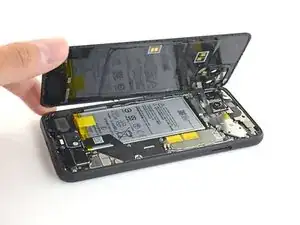
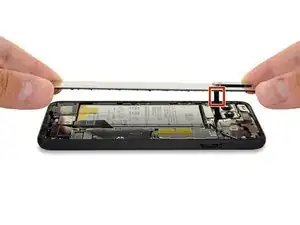
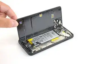
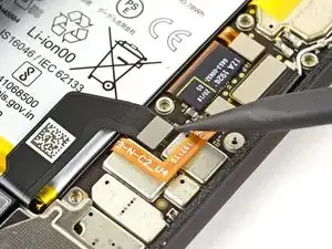
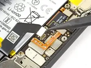
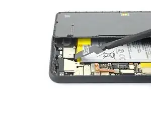
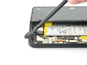
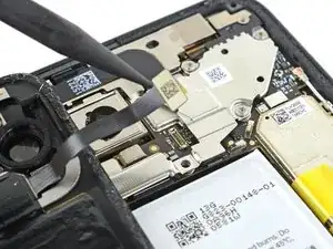
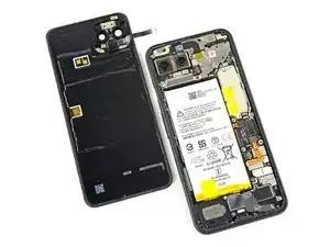
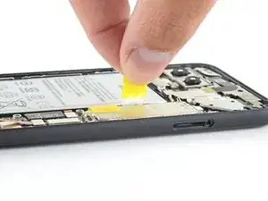
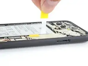
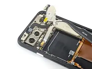
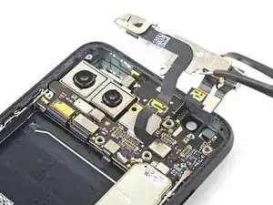
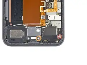
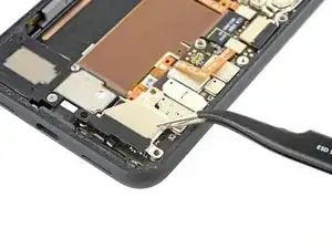
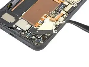
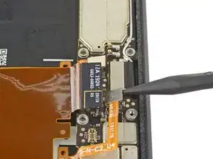
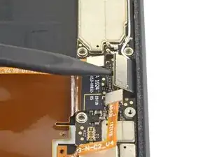
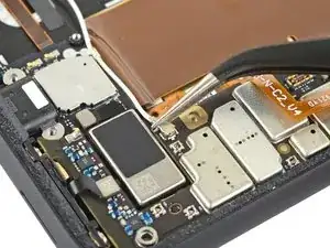
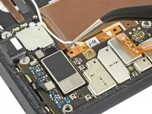
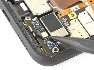
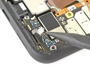
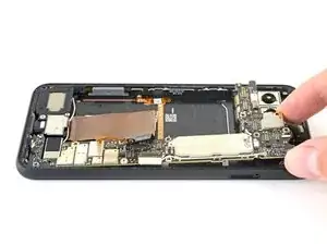
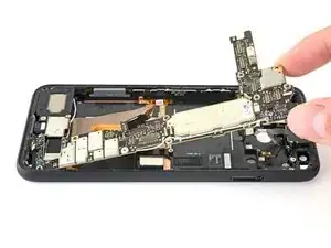
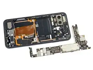
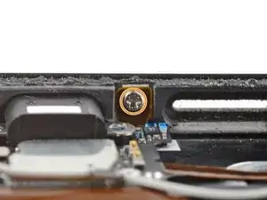
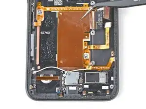
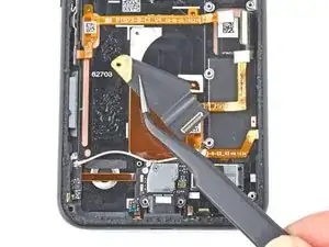
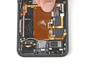
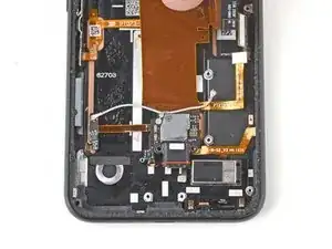
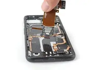
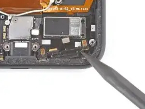
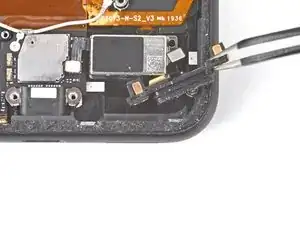
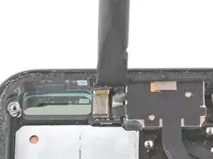
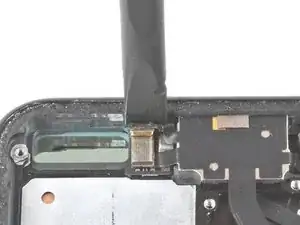
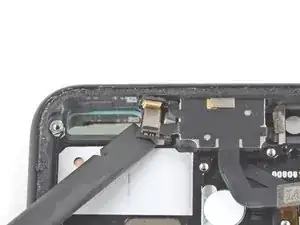
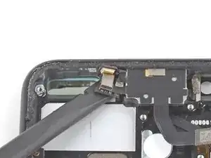
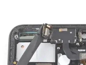
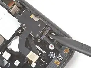
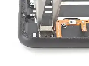
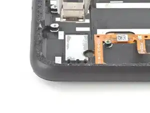
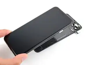
Use this guide to replace the screen on your Google Pixel 4.

Note: Follow this guide to replace a screen that's pre-installed in a new frame (a.k.a. chassis). You'll need to transplant all of your phone's internals to the new screen. If you're replacing the display panel by itself, follow this guide instead.

For your safety, discharge your battery below 25% before disassembling your phone. This reduces the risk of a dangerous thermal event if the battery is accidentally damaged during the repair.

This guide requires a replacement battery. Do not reuse the battery after it has been removed, as doing so is a potential safety hazard.

Caution: Google warns that disassembly of the front laser assembly could result in hazardous exposure to invisible infrared laser emissions. Read their safety warnings here.

  1. VbMFcJIqjkF2oOxL
    VbMFcJIqjkF2oOxL
    T2OsClj3mdTufoeA
    Jb5M1CAKCkCmZejc
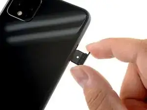
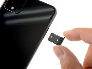
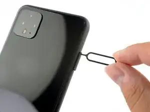
    • Insert a SIM eject tool, bit, or a straightened paper clip into the small hole on the SIM card tray on the left edge of the phone.

    • Press firmly to eject the tray.

    • Remove the SIM card tray.

  2. Hvp1kuHwJo1AClCp
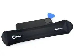
    • Prepare an iOpener and apply it to the bottom edge of the back panel for one minute.

    • A hair dryer, heat gun, or hot plate may also be used, but be careful not to overheat the phone—the display and internal battery are both susceptible to heat damage.

  3. VK4rWKHPMxSBgjeI
    VK4rWKHPMxSBgjeI
    GS4NhjEZM3SCXJcR
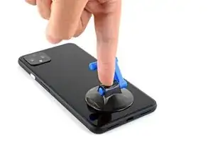
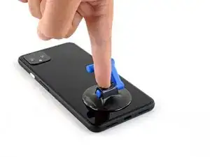
    • Apply a suction cup to the heated edge of the back panel by pressing down on it to create suction, as close to the edge as possible.

    • If your back glass is badly cracked, covering it with a layer of clear packing tape may allow the suction cup to adhere. Alternatively, very strong tape may be used instead of the suction cup. If all else fails, you can superglue the suction cup to the broken panel.

  4. mkgNQMFVCGsIjSWI
    mkgNQMFVCGsIjSWI
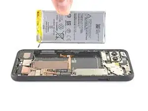
    ZcuoIwCBSbZQv1Jp
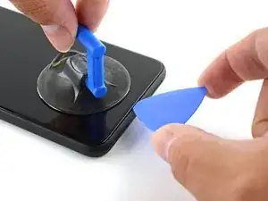
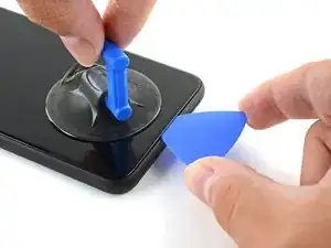
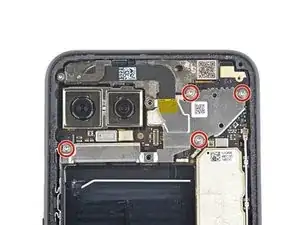
    • Pull up on the suction cup with strong, steady force to create a gap between the back panel and the frame.

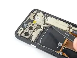
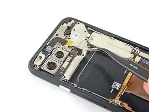
    • Depending on the age of your phone, this may be difficult. If you are having trouble, apply more heat to the edge and try again.

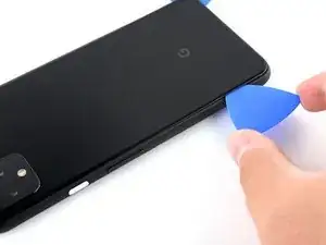
    • Insert the point of an opening pick into the gap.

  5. JPn1p4UL3KeHgTlm
    JPn1p4UL3KeHgTlm
    rerDsh5OJUS5DXft
    pq3vfvBe5v5htEJY
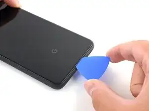
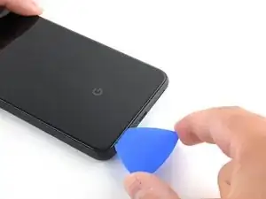
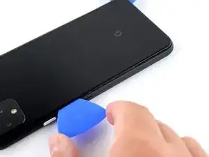
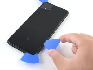
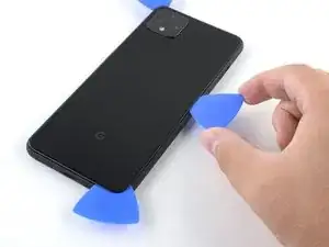
    • Slide the opening pick across the bottom towards the left corner to slice the adhesive.

    • With the pick still inserted, slide it from the bottom left corner over to the bottom right corner to completely slice the bottom side adhesive.

    • Leave the pick inserted in the bottom right corner to prevent the adhesive from re-sealing.

  6. bmjILIENBtpPcpxn
    • Prepare an iOpener and apply it on the left edge of the phone for one minute.

  7. GQ32GFimDFPnCaIN
    GQ32GFimDFPnCaIN
    KwMHik5nQYlWV3HD
    • Insert a second opening pick underneath the back panel directly over the charge port.

    • Slide the opening pick to the bottom left corner of the phone.

  8. 3wRXCsDVIiReHwDt
    3wRXCsDVIiReHwDt
    TsAtoOUWx5OUtfJw
    • Slide the opening pick around the bottom left corner and across the left side of the phone to slice the adhesive.

    • The adhesive can be very gummy. Push the pick in and out in a sawing motion to help with slicing.

    • Stop when you reach the top left corner, near the camera, and leave the pick inserted.

  9. qPt1cI1qIYhrYhrk
    • Prepare an iOpener and apply it on the right edge of the phone for one minute.

  10. 3MaLYKdcXwMGfmHm
    3MaLYKdcXwMGfmHm
    nNHbQECIIHKXCkeA
    dgKAYchvRQfbG4ZJ
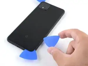
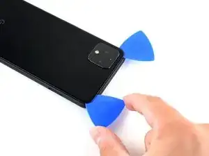
    • With the first two opening picks still in place, insert a third pick on the lower part of the righthand side.

    • Slide the opening pick up towards the top of the phone, slicing the right side's adhesive.

    • Stop when you reach the top right corner, and leave the pick inserted.

  11. pdXuWBOPnOHID4vo
    pdXuWBOPnOHID4vo
    I1Y2GTUYJV4tftII
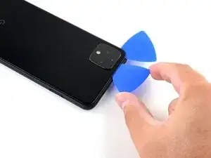
    • Slide the third opening pick around the top right corner and across the top side of the phone, slicing the final strip of adhesive.

  12. HySfZPvhGRSUENZS
    HySfZPvhGRSUENZS
    54ZsgXBi4YYA6vBS
    YMgGdiVcyxhx52e1
    • Once you have sliced around the perimeter of the phone, carefully lift the right edge of the back cover, opening it like a book.

    • Do not try to pull the panel all the way off yet, as it is still connected to the phone.

  13. iFNKHEbN5C5UEQkS
    iFNKHEbN5C5UEQkS
    B5L3GJWi4AWfOxaI
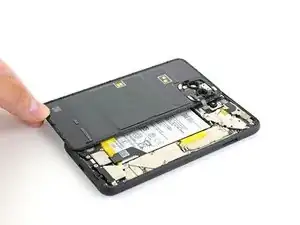
    • Continue swinging open the back panel until you can rest it on the left edge the phone, being careful not to put any stress on the attached ribbon cable.

    • During reassembly, this is a good point to power on your phone and test all functions before re-sealing the back panel. Be sure to power your phone back down completely before you continue working.

    At this point I suggest taking a photo of what you're seeing in there. This way you can make sure you put it all back the way it was when you're done.

    Brian Wood -

  14. cDEhvBgNJQUZJ2NE
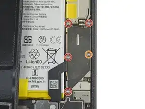
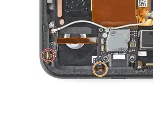
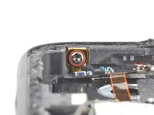
    • Remove the five T3 Torx screws securing the battery connector shield:

    • Four 4.0 mm screws

    • One 2.1 mm screw

    • Throughout this repair, keep track of each screw and make sure it goes back exactly where it came from.

    Does anyone know where I can get a replacement T3 - 2.1mm screw (the one circled in orange)? I lost this screw during the battery replacement. Had it, dogs fought, had to get up to break it up, and couldn’t find it. I swore I put it on the mat, but I couldn’t find it when I got back to the table. :(

    Nikki Chan -

  15. DpgvSry4M16dxYBf
    DpgvSry4M16dxYBf
    Tgut2yL1UUMP6SWV
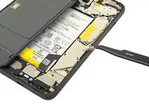
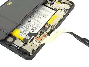
    • Use a pair of tweezers to remove the battery connector shield.

  16. A34sTTTFGUNelCdO
    A34sTTTFGUNelCdO
    SBgRCm6ApbKbQuCr
    • Whenever you use the spudger near the battery, be very careful not to puncture the battery.

    • Using the pointed end of a spudger, pry the battery connector straight up from the motherboard to disconnect the battery.

    • To re-attach press connectors like this one, carefully align and press down on one side until it clicks into place, then repeat on the other side. Do not press down on the middle. If the connector is misaligned, the pins can bend, causing permanent damage.

  17. aSUOVtDFdAFw6ufa
    aSUOVtDFdAFw6ufa
    E22f6ZaNgbVi2xET
    • Using the flat end of a spudger, gently fold the battery cable over so it doesn't accidentally make contact during the rest of your repairs.

  18. XhJoRsZlHgH4g5iJ
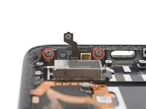
    • Use a T3 Torx driver to remove the two 4 mm screws securing the back panel connector cover.

  19. LouDYcubQQ312jgD
    LouDYcubQQ312jgD
    sVhpSIsBpW1NlJCT
    • Use a pair of tweezers to remove the back panel connector cover.

  20. HmoWeEMDomqaJL4d
    HmoWeEMDomqaJL4d
    jhUrNSsNsSZVYYNb
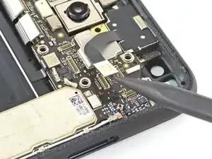
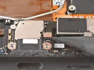
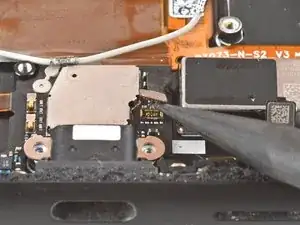
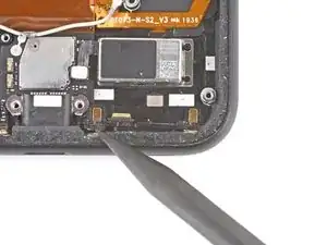
    • Using the pointed end of a spudger, pry up and disconnect the back panel connector.

  21. 2XIeuefUddCBWJBf
    • Remove the back panel.

    • During reassembly, follow this guide to install custom-cut adhesives for your device.

    • Follow this guide if you are using a pre-cut adhesive card.

    Why does the kit not come with the back panel adhesive?

    It's not cheap to get the full kit, and it seems like it's such a small thing to include.

    I ended up re-using the existing back panel adhesive and now a bit worried that it's not as strong and I will have issues with water or moisture getting into the device more easily.

    Mike Y -

  22. vsQtZECg1AKRxDNS
    vsQtZECg1AKRxDNS
    1iKUwRFf55WPTDZ3
    64VaExVETwEM64D5
    • Pull on the yellow pull tab of the adhesive strip with steady force.

    • If the adhesive becomes hard to pull, you can roll it around a spudger and continue pulling.

    • Continue firmly pulling up on the adhesive strip with constant force. If you're using a spudger, spin it every so often to keep the exposed section of the pull tab as short as possible.

    • This may take a lot of force.

    • These adhesive pull tabs are very prone to snapping in half during this process. Pull as slowly as possible.

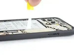
    • If the adhesive pull tabs are not stretching, fill a plastic dropper or syringe with high concentration (>90%) isopropyl alcohol and apply a few drops under the left edge of the battery. Give the alcohol a minute to weaken the battery adhesive.

    • Continue this process for each of the three pull tabs, until all are either out or have snapped in half.

    These are basically like command adhesive strips. If you don't get them off by pulling the tab you can pry them up but it is not easy. This is three strips of strong adhesive.

    Brian Wood -

    I pulled the adhesive strips upwards and they just torn leaving most of the adhesive beneath the battery. Battery is impossible to remove now.

    Denys Čumak -

    I too have experienced something like that. In this case I followed step 22 below to push the opening pick in and force it away from the adhesive. Some strength will be required. The key is to apply balanced force to prevent the battery from being deformed and damaged.

    hedgehog_camara -

  23. l2fY2QMAGemF5Kl1
    l2fY2QMAGemF5Kl1
    IWAyH4OHf2o2dMHr
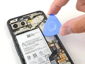
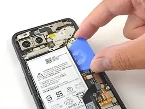
    • If the battery tabs snapped during removal, insert an opening pick on the upper right edge of the battery, slicing the adhesive underneath.

    • Even if you successfully removed all three adhesive pull tabs, using an opening pick to dislodge the battery may be helpful.

    • Don't insert the opening pick on or anywhere below the grip sensor cable, as the pick can damage the charge port flex cable located underneath the battery.

    The grip sensor cable picture here is incorrect for my pixel 4; on mine it runs straight from the connector on the right to the left edge of the case, then makes a 90° turn downward to where it connects to the sensor. The result was that I tore the cable because I was using the picture as a guide. I've taken a picture of the alternative placement on mine and I'll send it to the iFixit people to update this guide.

    Dave P Jarzembski Owen -

    At the bottom end of the battery there is a thin white antenna cable, somewhat hidden between battery and speaker / charging unit. It is also a bad idea to use a pick on the lower adhesive strip. In my case the cable glued to the rest of the strip and I damaged it when lifting the battery.

    David -

  24. E5FBP3CiWZbnNiWO
    E5FBP3CiWZbnNiWO
    pcrMlAEWQhMEw6Ub
    • Do not reuse the battery if it has been deformed or damaged, as doing so is a potential safety hazard. Replace it with a new battery.

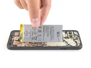
    • Lift the battery up and away from the phone to remove it. You may need to peel the battery away from any leftover adhesive tabs.

    • If there's any alcohol solution remaining in the phone, carefully wipe it off with a lint-free cloth or allow it to air dry before installing your battery.

    • To install a replacement battery:

    • If you're using stretch release adhesive, apply them onto the battery. Otherwise, apply some double-sided tape, or pre-cut adhesive strips in the phone's battery well, being careful not to cover the charge port flex cable. Peel away any tape liners to expose the adhesive.

    • Temporarily re-connect the battery's connector to the motherboard socket. This ensures that the battery is properly positioned.

    • Lay the battery in place and press firmly.

    • Disconnect the battery connector from its motherboard socket and resume re-assembly.

    There is a better guide for applying the back adhesive. Search out the guide for the pixel 4 back adhesive on this website. It sucks that they didn't include it here, and I messed it up by trying to decipher these generic instructions.

    Joe Gaughran -

    Thanks for this @joegaughran - saved me a problem. For others, the guide can be found here: How to Replace the Back Panel Adhesive on Your Google Pixel 4

    phzdw -

  25. ygGJW3UI3PktsgxM
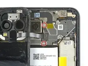
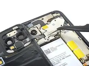
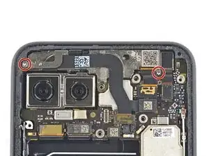
    • Use a T3 Torx driver to remove the four 4 mm screws securing the camera connector cover.

  26. pVBTaJwqYJwWPDAD
    pVBTaJwqYJwWPDAD
    ueDjTwuBIeNkWU14
    KbS4tAZ3dsh2uVPm
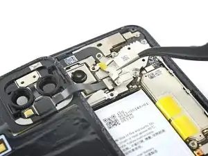
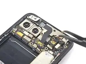
    • Using a pair of tweezers, tilt the camera cover up and slide it out of the retaining slot on the upper right corner of the phone to remove.

  27. 4ERntGXAvi3nLTBh
    4ERntGXAvi3nLTBh
    uldFkV5Z1GFOo1EP
    tfpTBGk3LSQGYMs4
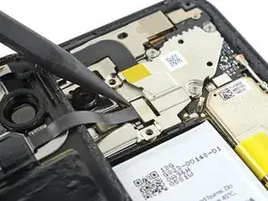
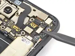
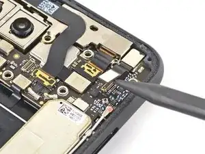
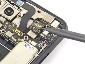
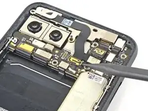
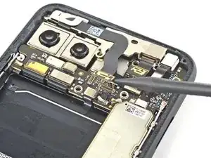
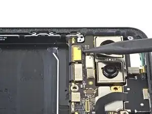
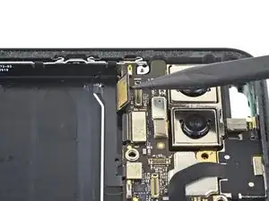
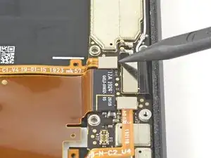
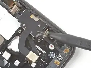
    • Using the pointed end of a spudger, pry the camera and sensor connectors straight up from the motherboard.

  28. rdfWWfiNJPOivoDj
    rdfWWfiNJPOivoDj
    gKhMS6XGZLPNnAvq
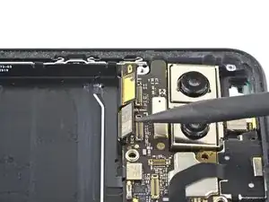
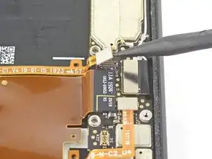
    • Disconnect the additional sensor connector.

  29. NQYrCfWdlTxlL1Ai
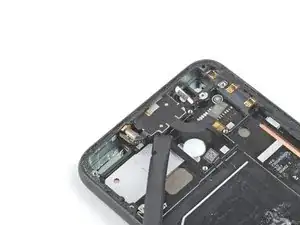
    • Use a T3 Torx driver to remove the two 2.4 mm screws securing the front camera and sensor assembly.

  30. HMT3Cvwsft2g3PQs
    HMT3Cvwsft2g3PQs
    TxOxQJrGCZnij3wL
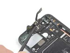
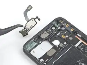
    • Use a pair of tweezers to remove the front camera and sensor assembly.

  31. SKViUNxEXdOuOGnU
    • Remove the two T3 Torx screws securing the vibration motor cover:

    • One 4.2 mm screw

    • One 4.4 mm shouldered screw

  32. ZTchiPrJY4ucPpOb
    ZTchiPrJY4ucPpOb
    pYBKCDkpmTbB4rgx
    • Use a pair of tweezers to remove the vibration motor shield.

  33. UnBsJgXiFWWFup2S
    UnBsJgXiFWWFup2S
    kueJ4AJkT2XSRbjm
    Ofk1EQJZUqINxiw5
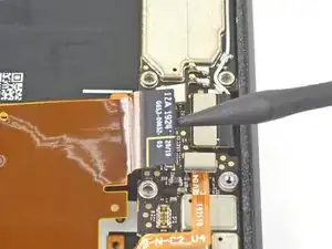
    • Use the pointed end of a spudger to disconnect the two rear-facing camera connectors from the motherboard.

    • Disconnect the side buttons connector from the motherboard.

  34. As3YwaxaRrahDWAu
    As3YwaxaRrahDWAu
    LRffaTrr16RZZFOy
    • Disconnect the earpiece speaker connector from the motherboard.

  35. DHn3gbUVDvgTZXpX
    DHn3gbUVDvgTZXpX
    sRMDWoULPXiyHlMT
    CTpA3ZiyOgGZijmH
    • Disconnect the left grip sensor connector from the motherboard.

    • Disconnect the charge port connector from the motherboard.

  36. NEXjC1TBigkpcVJG
    NEXjC1TBigkpcVJG
    QIIIeobyC3OrNklL
    • Disconnect the right grip sensor connector from the motherboard.

    • Disconnect the display connector from the motherboard.

  37. eQVvMNBZWPl1E3Ln
    eQVvMNBZWPl1E3Ln
    ZqpZFGdLTckVRWTW
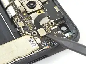
    • Use a pair of tweezers to disconnect the antenna connector from the charging assembly by pulling it straight up from the motherboard.

    What is it for? The white cable in here.

    Haykuhi Arzumanyan -

    It is the antenna.

    Daniele Carminati -

    What kind of antenna is it? Wi-Fi?

    net net -

  38. wXemCjIUAhCVZge1
    wXemCjIUAhCVZge1
    RBOKUKtmJDkuX1Wo
    • Disconnect the bottom microphone connector from the motherboard.

  39. IVbmTQfFpUZDxPIG
    IVbmTQfFpUZDxPIG
    VlJHTLNFejKvqwpD
    CxlXVTAEvQoYyZqG
    • Slowly lift out the motherboard, being careful not to snag any ribbon cable connectors.

    • The rear-facing camera module connectors loop around the motherboard, and the camera module is not secured to the phone, so it may lift out with the motherboard during this step.

    • Completely remove the motherboard.

    • When reinstalling the motherboard, check that no ribbon cable connectors are caught underneath.

  40. Mk2qhQoH3OcIbU3F
    Mk2qhQoH3OcIbU3F
    4mBJ4oyENXOyIR5g
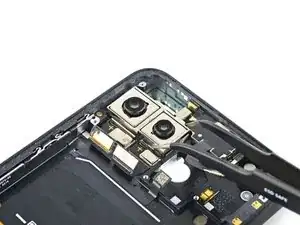
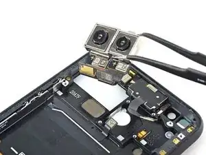
    • Use a pair of tweezers to remove the rear-facing camera module.

  41. YaBO4ouA5KgKpSDa
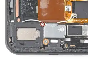
    • Use a T3 Torx driver to remove the two screws securing the loudspeaker:

    • One 4.2 mm screw

    • One 4.4 mm shouldered screw

  42. GEDWKwOEicOrK2V1
    GEDWKwOEicOrK2V1
    uIHRJgNPLEyRXMAE
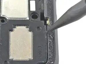
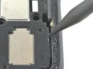
    • Use the pointed end of a spudger to push the loudspeaker towards the battery, creating a small gap between the loudspeaker and the phone's frame.

    • The loudspeaker is held in place by a small retaining clip hidden underneath the left edge of the frame.

  43. GN2NCmd4dlsyGOuS
    GN2NCmd4dlsyGOuS
    ngDI6VhvRxpOVl4Y
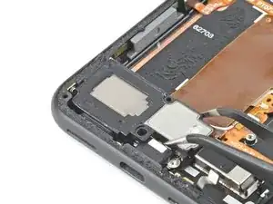
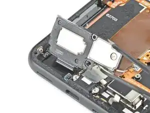
    • Use a pair of tweezers to remove the loudspeaker, pivoting it up and out of the phone.

    • If the loudspeaker doesn't want to pivot up, try pushing it closer to the battery.

  44. EWFYskJc1CSp1tXS
    EWFYskJc1CSp1tXS
    r6stDBIQenoyiJTh
    • Use the pointed end of a spudger to disconnect the vibration motor's press connector from the charging assembly.

  45. 4h1sSm4XuA6Mn1q3
    4h1sSm4XuA6Mn1q3
    lVQPpYSLNGxjEqnL
    OePAdWJEnFUnnRpw
    • Use a T3 Torx driver to remove the two screws securing the charging assembly to the frame:

    • One 2.1 mm screw on the left side of the frame.

    • One 2.1 mm screw on the bottom side of the frame.

  46. uHNU2Lx1R3CrFAXf
    uHNU2Lx1R3CrFAXf
    uT1bqD2rgcmktTBM
    • Use your fingers or a pair of tweezers to peel back the ribbon cable that's adhered to the phone's frame.

    • The ribbon cable is secured with some light adhesive.

  47. NeTWigFlfy1lt1Cs
    NeTWigFlfy1lt1Cs
    VgvS1JYeZYSCR24q
    yDcY2kO1PYwKV3ah
    • Remove the charging assembly.

  48. QJWkvJlSOdyNSCpN
    • Use a T3 Torx driver to remove the two 3.3 mm shouldered screws securing the bottom microphone assembly to the frame's lower edge.

  49. G6agAGAb14V6GFM4
    G6agAGAb14V6GFM4
    UwyywVfvvdYD5XC5
    a5RCObv2ZBVkL4V3
    • Insert the pointed end of a spudger into the divot between the microphone assembly and the frame.

    • Slide the pointed end of the spudger from left to right, separating the microphone assembly and the frame.

    • Remove the microphone assembly using your fingers or a pair of tweezers.

  50. D4DJ2chSokNwsUZK
    D4DJ2chSokNwsUZK
    EcuJObr5VNnHlYyG
    • Use the flat end of a spudger to slice through the adhesive securing the top module to the top of the frame.

  51. 4jYIk5nuVTSSXokO
    4jYIk5nuVTSSXokO
    doUe1oPvfrOOs3Us
    replkwYYVTqZDhOI
    • Use the flat end of a spudger to slice through the adhesive securing the left side of the top module to the body of the frame.

  52. JFZRFJZ4wbrt5isH
    JFZRFJZ4wbrt5isH
    QJPF3A3aObCCFBKT
    • Use the pointed end of a spudger to separate the right side of the top module from the body of the frame.

  53. L6nIHeIZ43LFRFuT
    L6nIHeIZ43LFRFuT
    CKjNTyxqhKZJ6JwF
    LEGRMojVvTnUXuqQ
    • Use the flat end of a spudger to separate the top module from the top speaker.

    • Remove the top module.

  54. VcnVKVbxDOINS3rb
    VcnVKVbxDOINS3rb
    RwD1BreUBT5bkWxu
    • Use a pair of pliers to firmly grip the vibration motor near the bottom right of the device.

    • Pull straight up steadily until the motor separates from the frame.

    • Grip the vibration motor by the side opposite its cable and be sure not to damage the cables covering the rest of the motor.

  55. cZ6j1TTcjCnOSKkK
    • You're now left with the screen.

Conclusion

Compare your new replacement part to the original part—you may need to transfer remaining components or remove adhesive backings from the new part before installing.

To reassemble your device, follow the above steps in reverse order.

Take your e-waste to an R2 or e-Stewards certified recycler.

Repair didn’t go as planned? Try some basic troubleshooting, or ask our Answers community for help.

Clay Kim

Member since: 16/02/21

9619 Reputation

3 comments

I am very glad I was able to disassemble it. And now ? How do I reassemble ?

John -

Just a heads up. There are two rubber pads that might fall out. One is for the front facing camera frame. The other goes above a silver padded piece on the top left when looking from the back below the camera module. Look for tube videos if you can't find it. I found this out the hard way. :)

Melissa S -

Fantastic directions. Great job.

I'm confused though. I see 3 scenarios:

1. Was this tutorial made specifically to replace the screen, and each step is required?

2. Is it recommended to use this order and stop at the component I want to replace?

3. Or can some components be replaced sooner and more directly in the process (using this guide for location and technique)?
Eric Smith -