Well drainage
Well drainage means drainage of agricultural lands by wells. Agricultural land is drained by pumped wells (vertical drainage) to improve the soils by controlling water table levels and soil salinity.
Introduction
Subsurface (groundwater) drainage for water table and soil salinity in agricultural land can be done by horizontal and vertical drainage systems.
Horizontal drainage systems are drainage systems using open ditches (trenches) or buried pipe drains.
Vertical drainage systems are drainage systems using pumped wells, either open dug wells or tube wells.

Both systems serve the same purposes, namely water table control and soil salinity control .
Both systems can facilitate the reuse of drainage water (e.g. for irrigation), but wells offer more flexibility.
Reuse is only feasible if the quality of the groundwater is acceptable and the salinity is low.
Design
Although one well may be sufficient to solve groundwater and soil salinity problems in a few hectares, one usually needs a number of wells, because the problems may be widely spread.
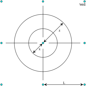
The wells may be arranged in a triangular, square or rectangular pattern.
The design of the well field concerns depth, capacity, discharge, and spacing of the wells.[1]
- The discharge is found from a water balance.[2]
- The depth is selected in accordance to aquifer properties. The well filter must be placed in a permeable soil layer.
- The spacing can be calculated with a well spacing equation using discharge, aquifer properties, well depth and optimal depth of the water table.
The determination of the optimum depth of the water table is the realm of drainage research .
Flow to wells


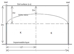
The basic, steady state, equation for flow to fully penetrating wells (i.e. wells reaching the impermeable base) in a regularly spaced well field in a uniform unconfined (preactic) aquifer with a hydraulic conductivity that is isotropic is:[1]
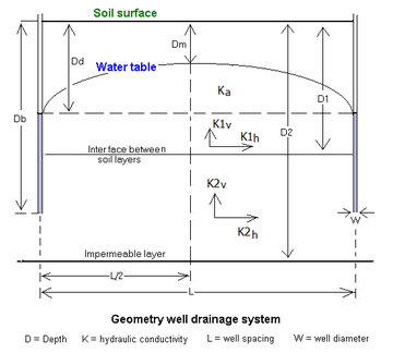
where Q = safe well discharge - i.e. the steady state discharge at which no overdraught or groundwater depletion occurs - (m3/day), K = uniform hydraulic conductivity of the soil (m/day), D = depth below soil surface, = depth of the bottom of the well equal to the depth of the impermeable base (m), = depth of the watertable midway between the wells (m), is the depth of the water level inside the well (m), = radius of influence of the well (m) and is the radius of the well (m).
The radius of influence of the wells depends on the pattern of the well field, which may be triangular, square, or rectangular. It can be found as:
where = total surface area of the well field (m2)and N = number of wells in the well field.
The safe well discharge (Q) can also be found from:
where q is the safe yield or drainable surplus of the aquifer (m/day) and is the operation intensity of the wells (hours/24 per day). Thus the basic equation can also be written as:
Well spacing
With a well spacing equation one can calculate various design alternatives to arrive at the most attractive or economical solution for watertable control in agricultural land.
The basic flow equation cannot be used for determining the well spacing in a partially penetrating well-field in a non-uniform and anisotropic aquifer, but one needs a numerical solution of more complicated equations.[3]
The costs of the most attractive solution can be compared with the costs of a horizontal drainage system - for which the drain spacing can be calculated with a drainage equation - serving the same purpose, to decide which system deserves preference.
The well design proper is described in[1]
An illustration of the parameters involved is shown in the figure. The hydraulic conductivity can be found from an aquifer test.

Software
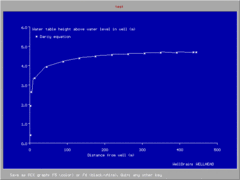
The numerical computer program WellDrain[3] for well spacing calculations takes into account fully and partially penetrating wells, layered aquifers, anisotropy (different vertical and horizontal hydraulic conductivity or permeability) and entrance resistance.
Modelling
With a groundwater model that includes the possibility to introduce wells, one can study the impact of a well drainage system on the hydrology of the project area. There are also models that give the opportunity to evaluate the water quality.
SahysMod[4] is such a polygonal groundwater model permitting to assess the use of well water for irrigation, the effects on soil salinity and on depth of the water table.
See also
References
- Boehmer, W.K., and J.Boonstra, 1994, Tubewell Drainage Systems, Chapter 22 in: H.P.Ritzema (ed.), Drainage Principles and Applications, Publ. 16, International Institute for Land Reclamation and Improvement (ILRI),Wageningen, The Netherlands. pp. 931-964, ISBN 90-70754-33-9 . On line :
- ILRI, 1999, Drainage and Hydrology/Salinity: Water and salt balances, 29 pp. Lecture notes of the International Course on Land Drainage (ICLD), International Institute for Land Reclamation and Improvement (ILRI), Wageningen, The Netherlands. On line :
- ILRI, 2000, Subsurface drainage by (tube)wells: Well spacing equations for fully and partially penetrating wells in uniform or layered aquifers with or without anisotropy and entrance resistance, 9 pp. Principles used in the "WellDrain" model. International Institute for Land Reclamation and Improvement (ILRI), Wageningen, The Netherlands
Download "WellDrain" software from : , or from : - SahysMod, Spatial Agro-Hydro-Salinity Model: Description of Principles, User Manual, and Case Studies. SahysMod working group of the International Institute for Land Reclamation and Improvement, Wageningen, the Netherlands. On line: .
Download the model from : , or from :
External links
- Salinity Control and Reclamation Program (SCARP) using wells in the Indus valley of Pakistan.
- Website on waterlogging and land reclamation by horizontal and vertical drainage systems :