USS Spuyten Duyvil
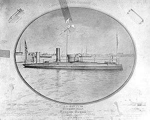
During the American Civil War, the Union Navy suffered heavy losses from the explosion of Confederate torpedoes. This experience prompted the Union Navy to design and build vessels capable of using this new weapon. One effort along this line resulted in a screw steam torpedo boat originally called Stromboli, but later called Spuyten Duyvil, after the Spuyten Duyvil area in New York City.
 | |
| History | |
|---|---|
| Name: | USS Spuyten Duyvil |
| Ordered: | 1 June 1864 |
| Builder: | Samuel M. Pook |
| Launched: | September 1864 |
| Out of service: | 1866 |
| Fate: | Sold, 1880 |
| General characteristics | |
| Type: | Torpedo boat |
| Displacement: | 207 long tons (210 t) |
| Length: | 84 ft 2 in (25.65 m) |
| Beam: | 20 ft 8 in (6.30 m) |
| Draft: | 7 ft 6 in (2.29 m) |
| Propulsion: | Screw steamer |
| Speed: | 5 knots (9.3 km/h; 5.8 mph) |
| Complement: | 23 officers and enlisted |
| Armament: | 1 × spar torpedo |
| Armor: |
|
History
Stromboli was designed by the Chief Engineer of the United States Navy, Captain William W. Wood, who supervised her construction at New Haven, CT, by Samuel M. Pook. The contract for her construction was dated 1 June 1864. Confirmed records of her launching and commissioning have not been found – though period records indicate that she was completed in only three months. On 19 November 1864, the boat was renamed Spuyten Duyvil. On 25 November 1864, she successfully fired two torpedoes. Late in November 1864, Commodore Charles Stewart Boggs was placed in charge of Spuyten Duyvil, Picket Boat No. 6, and steam tug John T. Jenkins which had been chartered to tow the former vessels to Hampton Roads, VA. Upon arriving at Baltimore, MD on 2 December, Boggs turned the vessels over to Commodore T. A. Dornin who placed them under First Assistant Engineer John L. Lay for the remainder of the trip to Hampton Roads. The vessels arrived at Norfolk, VA on 5 December.
The torpedo boat was ordered up the James River a week later to help assure Union control of that vital waterway during General Ulysses S. Grant's drive on Richmond, VA. She arrived at Akin's Landing on 15 December, and she operated on the upper James slightly below the Confederate obstructions through most of the remaining months of the campaign. A highlight of her service came on the night of 23/24 January 1865 when the Confederacy's James River Squadron launched its downstream assault on the Union squadron. During the ensuing Battle of Trent's Reach, Spuyten Duyvil supported Onondaga, the only monitor then on the river.
After General Robert E. Lee evacuated Richmond, Spuyten Duyvil used her torpedoes to help clear the obstructions from the river. Her work made it possible for President Abraham Lincoln to steam up in Malvern and, after Rear Admiral David Dixon Porter's flagship ran aground, to be rowed in a launch safely to the former Confederate capital.
Following the end of the war, Spuyten Duyvil continued to clear obstructions from the James. She then returned to the New York Navy Yard where she was placed in ordinary in 1866. In the years that followed, she was used for developmental work and was modified with many experimental improvements. The ship disappeared from the Navy list in 1880.
Use of the term "torpedo "
In this case, as in the common use of the term in the 19th century, torpedo refers to a device sometimes rigged as a spar torpedo that would now be considered to be a type of naval mine, not being the self-propelled device (called a locomotive torpedo) common in the 20th century.
Engineering
The following segments are an in-depth analysis of the vessel and the torpedo mechanisms, heavily based on an article written by the British publication Engineering in 1866. The torpedo apparatus is also described in US patent 46853, Improved Apparatus for Operating Submarine Shells or Torpedoes, issued to William Wood and John L. Lay 14 Mar 1865.


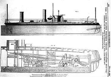
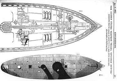
The plans for the Spuyten Duyvil as referenced by the article.
Materials and layout
She was constructed of timber, and the deck, as well as the sides near the water line is protected by iron plating 1 in (25 mm) thick. Shown in elevation in Fig. 1, and section in Fig. 2, the pilothouse was placed just a little ahead of the middle of the vessel with a 5 ft (1.5 m) outside diameter, and being constructed, for a height of 2 ft 8 in (810 mm) above the deck, of twelve layers of iron plates, each 1 in (25 mm) in thickness. The total weight of the pilothouse was 25,000 lb (11,000 kg).
Propulsion and pumping
The vessel is propelled by a single four-bladed screw, and the engines for working the propeller were constructed at Mystic, CT, by Mallory and Co. When at her usual draft the vessel will steam 9 miles per hour (14 km/h); but when immersed to the gunwale, ready for going into action, her speed is reduced to from 3½ to 4 miles per hour (6 km/h); her movements are stated to be quite noiseless. She is provided with stowage for 160 tons of coal, equal to eight days' consumption. The pumps used for filling and emptying the compartments, by which the degree of immersion of the vessel is regulated, are a pair of Andrews's centrifugal pumps of the size known as "No. 6." These pumps are situated a short distance ahead of the pilothouse, as shown in Figs. 2 and 3 and they are each driven by a small oscillating engine, the crankshaft of each engine being coupled direct to the shaft of the pump to which it belongs. One of these pumps – that on the port side – has its suction pipes so arranged that, in addition to drawing from the water compartments or the sea, it can draw from the reservoir or tank in the fore part of the vessel, in which the torpedoes are placed.
Torpedo placement machinery
The torpedo-laying machinery was designed by Captain Wood, and constructed by the Clute Brothers, of Schenectady, NY. The general appearance of the vessel is shown by the side elevation and plan, Figs. 1 and 4, while in Figs. 2 and 3 are given, respectively, a longitudinal section and sectional plan, which show clearly the arrangement of the torpedo machinery. The length of the vessel over all is 84 ft 2 in (25.7 m), and her length from the after edge of her stern post to the forward edge of the gate frame is 73 ft 11 in (22.5 m), while her breadth was 20 ft 8 in (6.3 m). The depth of her hold is 9 ft 11½ in (3.04 m), and her draft when launched with 10 tons of torpedo machinery and 2½ tons of her propelling engines on board was 4 ft. When fully equipped, this draft was increased to 7 ft 5½ in (2.27 m), and, by pumping water into compartments provided for the purpose, as will be explained presently, this draft can be increased to 9 ft 1 in (2.8 m) when the vessel is going into action. At this latter draft the water is about level with the gunwale, but, owing to the arched form of the deck, the vessel has still under such circumstances 207 tons of displacement.
Torpedo ports
The lower part of the bow of the vessel, instead of being made solid as usual, is composed of two iron flaps, each hinged at the top, as shown in Figs. 1 and 2. When closed, the outer surfaces of these flaps correspond to the general shape of the bow, and, when the torpedo machinery is not being worked, they are kept down in their places by means of chains attached to them near their lower edges, and passing in through a pair of hawsepipes situated between the flaps. Each chain, after entering its hawsepipe, is attached to an iron rod, these rods passing into the vessel through stuffing-boxes at the inner ends of the hawsepipes. From the inner ends of these rods chains are led, over guide pulleys, to the ends of a winch, situated as shown in Figs. 2 and 3, and by means of this winch, which is worked by hand, the flaps can be closed when required. The opening of the flaps is effected by the arrangements shown in Figs. 1 and 4, from which it will be seen that each flap has a chain attached to its outside, and that these chains, after being led up over guide pulleys supported by brackets placed at the level of the gunwale, are crossed and then led down through hawseholes in the deck to the winch below. The chains for opening, in fact, form continuations of those for closing the flaps, or vice versa.
Sluice valve
At the bow of the vessel, within the space enclosed by the two flaps already described, there is an opening fitted with a sluice valve, as shown in Fig. 2. This valve slides vertically, and is raised and lowered by means of a screw, which can be worked by hand. The arrangement of gearing employed is shown in Fig. 3. When the sluice valve is opened, it admits the water into a strongly constructed iron reservoir 6 ft 2 in (1.9 m) long, 4 ft (1.2 m) deep, and varying from 2 ft 3 in to 3 ft (690 to 910 mm) wide. At the top of this tank there is a manhole fitted with a cover, hinged and fastened so that it can be easily removed and replaced; and from the lower part of the tank, a suction pipe proceeds to one of the Andrews's pumps. The aft end of the tank is fitted with a gunmetal sphere 18 in (460 mm) in diameter, this sphere being held by two flanges as shown in Fig. 2, so that it forms a ball-and-socket joint. It is through an opening in this sphere that the torpedo tube projected torpedoes from the vessel. This tube is about 20 ft (6.1 m) long, and has an external diameter of 5 in (127 mm) and an internal diameter of 3 in (76 mm). It was made by Morris, Tasker and Co., Philadelphia, PA and was considered a very superior example of workmanship.
Torpedo retention
The end of the tube which projects into the tank is furnished with a bell-mouthed casting of gunmetal, and to this is attached a light cylindrical casing of sheet iron, within which the torpedo to be fired is placed, the inside of the casing being furnished with ribs, upon which the torpedo rests. Each torpedo is furnished at its rear end with a knob, or button-shaped projection, and, when a torpedo is placed in the casing just mentioned, this knob is clipped by fingers carried at the end of a tubular rod, which slides through the main tube already described; and by this means the torpedo is held in place in the casing until fired.
Torpedo elevation
Within the spherical joint, the main tube is led through a kind of guide tube, which is capable of turning, in a vertical plane, upon side trunnions; These trunnions being supported by bearings which work in vertical guides, and are capable of being raised or lowered by the arrangement shown in Fig. 2. This arrangement is as follows: From each bearing a chain is led, over a guide pulley situated at the top of the guide belonging to that bearing, to an arm fixed on a rocking-shaft placed close to the floor of the vessel. On this rocking-shaft there is also fixed another arm, and from this a chain proceeds aft to the piston rod of a horizontal steam cylinder, placed as shown in Fig. 2. This cylinder is provided with a slide valve, by which the steam can be admitted to or released from the forward end of the cylinder at pleasure; and, when the steam is so admitted, it drives back the piston, and, by means of the arrangement of chains and rocking-shaft already described, raised the guide tube, through which the main tube passes, and thus depresses that end of the latter which carries the torpedo. The extent to which the piston in the steam cylinder is driven back, and, consequently, the extent to which the guide tube is raised, is regulated by means of a screw which passes through the back cylinder cover, this screw, which is furnished with a handwheel and check-nut, forming a stop against which the piston rests when driven back by the steam.
Torpedo projection
The machinery for projecting and withdrawing the torpedo tube consists of a couple of chain drums worked by gearing which is driven by a rotary engine made by Root, New York, NY. One of these drums is placed in the tank or reservoir in the bows of the vessel, and the chain from it is used for hauling in the tube. In order to prevent the chain from overriding on the drum, it is guided by passing through a suitable block which, as the drum revolves, is moved transversely along the drum and deposits the chain in regular coils. The transverse movement of the guiding block is given by a screwed spindle which has a pinion fixed on it gearing into a spur wheel on the chain drum. The hauling out of the torpedo carrier is effected by means of a chain attached to its inner end and led to the second chain drum which is placed above and slightly abaft the tank, as shown in Fig. 2. The arrangement adopted for guiding the chain is the same in this case as in that of the hauling-in drum. Each drum is loose upon its shaft, but is capable of being connected to it by a clutch, the two clutches being connected by levers so that they can be thrown into gear alternately. The tube can be run in and out by the machinery we have described at the rate of from 8 to 12 double strokes per minute.
Operation and reloading sequence
When firing a torpedo, the two flaps forming the lower part of the bow would be opened, the sluice raised, and the tube projected by means of the chain leading from the inner end to the hauling-out drum. The torpedo would then be thrust from the case at the end of the tube by means of the tubular rod to which the holding fingers are fixed, and, the torpedo being detached, the main tube would be withdrawn by means of the hauling-in chain. In order to place another torpedo in the case at the end of the tube the sluice has to be closed, and the tank having been emptied of water by the centrifugal pump already mentioned, the manhole at the top of the tank can be opened and access thus obtained to the torpedo holder. The emptying of the tank can be effected by the centrifugal pump in about four seconds, and the whole of the operations which we have described can be performed at such a rate that a torpedo can be discharged every three minutes if required.
Torpedo characteristics
The vessel was intended to use torpedoes containing 400 lb (180 kg) of black powder; but those actually employed by it contained 60 lb (27 kg) of fine powder of the kind known in the American service as No. 7. The "obstruction shells" have each an air space left round the powder, so as to allow the free expansion of the gases, and the torpedoes intended for use against vessels are of slightly less specific gravity than water, so that when released from the holder they rise slowly until they come against the bottom of the vessel under which they are placed. As will be seen by the section, Fig. 2, the powder is so placed in the torpedo that, when the later is released, it floats nearly upright with its point downwards. Within the torpedo case, on one side, is placed a tube, at the lower end of which is a percussion fuse in communication with the powder. At the upper end of the tube is a ball, which is held from falling upon the percussion fuse by a sliding pin placed beneath it. This pin passes out through the torpedo case, and has an eye formed at its outer end, as shown in Fig. 2. When the torpedo is placed in the casing at the end of the projecting tube, that side of the torpedo through which the sliding pin just mentioned projects is placed downwards, and one end of a cord is attached to the eye of the pin, and the other end to another eye fixed to the casing at the end of the projecting tube. The length of this cord is regulated according to the distance at which it is desired to fire the torpedo – the length generally employed being about 20 ft (6 m) — and it acts in the following manner: When the torpedo has been projected by means of the tube and released, the tube is of course drawn back, and as this movement takes place the cord is tightened, and the sliding pin is withdrawn from the torpedo case, this movement releasing the ball and allowing it to fall upon the percussion fuse, and explode the torpedo.
See also
- Union Blockade
- United States Navy
- List of United States Navy ships
References

- This article incorporates text from the public domain Dictionary of American Naval Fighting Ships. The entry can be found here.