Intermodulation
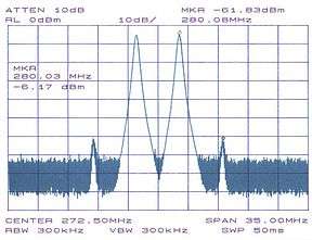
Intermodulation (IM) or intermodulation distortion (IMD) is the amplitude modulation of signals containing two or more different frequencies, caused by nonlinearities or time variance in a system. The intermodulation between frequency components will form additional components at frequencies that are not just at harmonic frequencies (integer multiples) of either, like harmonic distortion, but also at the sum and difference frequencies of the original frequencies and at sums and differences of multiples of those frequencies.

.png)
Intermodulation is caused by non-linear behaviour of the signal processing (physical equipment or even algorithms) being used. The theoretical outcome of these non-linearities can be calculated by generating a Volterra series of the characteristic, or more approximately by a Taylor series.[1]
Practically all audio equipment has some non-linearity, so it will exhibit some amount of IMD, which however may be low enough to be imperceptible by humans. Due to the characteristics of the human auditory system, the same percentage of IMD is perceived as more bothersome when compared to the same amount of harmonic distortion.[2][3]
Intermodulation is also usually undesirable in radio, as it creates unwanted spurious emissions, often in the form of sidebands. For radio transmissions this increases the occupied bandwidth, leading to adjacent channel interference, which can reduce audio clarity or increase spectrum usage.
IMD is only distinct from harmonic distortion in that the stimulus signal is different. The same nonlinear system will produce both total harmonic distortion (with a solitary sine wave input) and IMD (with more complex tones). In music, for instance, IMD is intentionally applied to electric guitars using overdriven amplifiers or effects pedals to produce new tones at subharmonics of the tones being played on the instrument. See Power chord#Analysis.
IMD is also distinct from intentional modulation (such as a frequency mixer in superheterodyne receivers) where signals to be modulated are presented to an intentional nonlinear element (multiplied). See non-linear mixers such as mixer diodes and even single-transistor oscillator-mixer circuits. However, while the intermodulation products of the received signal with the local oscillator signal are intended, superheterodyne mixers can, at the same time, also produce unwanted intermodulation effects from strong signals near in frequency to the desired signal that fall within the passband of the receiver.
Causes of intermodulation
A linear system cannot produce intermodulation. If the input of a linear time-invariant system is a signal of a single frequency, then the output is a signal of the same frequency; only the amplitude and phase can differ from the input signal.
Non-linear systems generate harmonics in response to sinusoidal input, meaning that if the input of a non-linear system is a signal of a single frequency, then the output is a signal which includes a number of integer multiples of the input frequency signal; (i.e. some of ).
Intermodulation occurs when the input to a non-linear system is composed of two or more frequencies. Consider an input signal that contains three frequency components at, , and ; which may be expressed as
where the and are the amplitudes and phases of the three components, respectively.
We obtain our output signal, , by passing our input through a non-linear function :
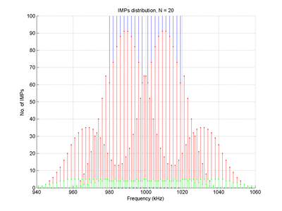
will contain the three frequencies of the input signal, , , and (which are known as the fundamental frequencies), as well as a number of linear combinations of the fundamental frequencies, each of the form
where , , and are arbitrary integers which can assume positive or negative values. These are the intermodulation products (or IMPs).
In general, each of these frequency components will have a different amplitude and phase, which depends on the specific non-linear function being used, and also on the amplitudes and phases of the original input components.
More generally, given an input signal containing an arbitrary number of frequency components , the output signal will contain a number of frequency components, each of which may be described by
where the coefficients are arbitrary integer values.
Intermodulation order

The order of a given intermodulation product is the sum of the absolute values of the coefficients,
For example, in our original example above, third-order intermodulation products (IMPs) occur where :
In many radio and audio applications, odd-order IMPs are of most interest, as they fall within the vicinity of the original frequency components, and may therefore interfere with the desired behaviour. For example, intermodulation distortion from the third order (IMD3) of a circuit can be seen by looking at a signal that is made up of two sine waves, one at and one at . When you cube the sum of these sine waves you will get sine waves at various frequencies including and . If and are large but very close together then and will be very close to and .
Passive intermodulation (PIM)
As explained in a previous section, intermodulation can only occur in non-linear systems. Non-linear systems are generally composed of active components, meaning that the components must be biased with an external power source which is not the input signal (i.e. the active components must be "turned on").
Passive intermodulation (PIM), however, occurs in passive devices (which may include cables, antennas etc.) that are subjected to two or more high power tones.[4] The PIM product is the result of the two (or more) high power tones mixing at device nonlinearities such as junctions of dissimilar metals or metal-oxide junctions, such as loose corroded connectors. The higher the signal amplitudes, the more pronounced the effect of the nonlinearities, and the more prominent the intermodulation that occurs — even though upon initial inspection, the system would appear to be linear and unable to generate intermodulation.
It is also possible for a single broadband carrier to generate PIM if it passes through a PIM generating surface or defect. These distortions would show up as side lobes in a telecommunication signal and interfere with adjacent channels and impede reception.
PIM can be severe problem in modern communication systems. Paths that share both high power transmission and the receive signal are most susceptible to this kind of interference. Once PIM interference finds its way to receive path, it can not be filtered or separated.[5]
Sources of PIM
Ferromagnetic materials are the most common materials to avoid and include ferrites, nickel, (including nickel plating) and steels (including some stainless steels). These materials exhibit hysteresis when exposed to reversing magnetic fields, resulting in PIM generation.
PIM can also be generated in components with manufacturing or workmanship defects, such as cold or cracked solder joints or poorly made mechanical contacts. If these defects are exposed to high RF currents, PIM can be generated. As a result, RF equipment manufacturers perform factory PIM tests on components, to eliminate PIM caused by these design and manufacturing defects.
PIM can also be inherent in the design of a high power RF component where RF current is forced to narrow channels or restricted.
In the field, PIM can be caused by components that were damaged in transit to the cell site, installation workmanship issues and by external PIM sources. Some of these include:
- Contaminated surfaces or contacts due to dirt, dust, moisture or oxidation.
- Loose mechanical junctions due to inadequate torque, poor alignment or poorly prepared contact surfaces.
- Loose mechanical junctions caused during transportation, shock or vibration.
- Metal flakes or shavings inside RF connections.
- Inconsistent metal-to-metal contact between RF connector surfaces caused by any of the following:
- Trapped dielectric materials (adhesives, foam, etc.), cracks or distortions at the end of the outer conductor of coaxial cables, often caused by overtightening the back nut during installation, solid inner conductors distorted in the preparation process, hollow inner conductors excessively enlarged or made oval during the preparation process.
- PIM can also occur in connectors, or when conductors made of two galvanically unmatched metals come in contact with each other.
- Nearby metallic objects in the direct beam and side lobes of the transmit antenna including rusty bolts, roof flashing, vent pipes, guy wires, etc.
PIM Testing
IEC 62037 is the international standard for PIM testing and gives specific details as to PIM measurement setups. The standard specifies the use of two +43 dBm (20W) tones for the test signals for PIM testing. This power level has been used by RF equipment manufacturers for more than a decade to establish PASS / FAIL specifications for RF components.
Intermodulation in electronic circuits
Slew-induced distortion (SID) can produce intermodulation distortion (IMD) when the first signal is slewing (changing voltage) at the limit of the amplifier's power bandwidth product. This induces an effective reduction in gain, partially amplitude-modulating the second signal. If SID only occurs for a portion of the signal, it is called "transient" intermodulation distortion.[6]
Measurement
Intermodulation distortion in audio is usually specified as the root mean square (RMS) value of the various sum-and-difference signals as a percentage of the original signal's RMS voltage, although it may be specified in terms of individual component strengths, in decibels, as is common with RF work. Audio IMD standard tests include SMPTE standard RP120-1994[6] where two signals (at 60 Hz and 7 kHz, with 4:1 amplitude ratios) are used for the test; many other standards (such as DIN, CCIF) use other frequencies and amplitude ratios. Opinion varies over the ideal ratio of test frequencies (e.g. 3:4,[7] or almost — but not exactly — 3:1 for example).
After feeding the equipment under test with low distortion input sinewaves, the output distortion can be measured by using an electronic filter to remove the original frequencies, or spectral analysis may be made using Fourier Transformations in software or a dedicated spectrum analyser, or when determining intermodulation effects in communications equipment, may be made using the receiver under test itself.
In radio applications, intermodulation may be measured as adjacent channel power ratio. Hard to test are intermodulation signals in the GHz-range generated from passive devices (PIM: passive intermodulation). Manufacturers of these scalar PIM-instruments are Summitek and Rosenberger. The newest developments are PIM-instruments to measure also the distance to the PIM-source. Anritsu offers a radar-based solution with low accuracy and Heuermann offers a frequency converting vector network analyzer solution with high accuracy.
See also
- Beat (acoustics)
- Audio system measurements
- Second-order intercept point
- Third-order intercept point, a metric of an amplifier or system related to intermodulation
- Luxemburg–Gorky effect
References
- Rouphael, Tony J. (2014). Wireless Receiver Architectures and Design: Antennas, RF, Synthesizers, Mixed Signal, and Digital Signal Processing. Academic Press. p. 244.
- Francis Rumsey; Tim Mccormick (2012). Sound and Recording: An Introduction (5th ed.). Focal Press. p. 538. ISBN 978-1-136-12509-6.
- Gary Davis; Ralph Jones (1989). The Sound Reinforcement Handbook (2nd ed.). Yamaha / Hal Leonard Corporation. p. 85. ISBN 978-0-88188-900-0.
- Passive Intermodulation Interference in Communication Systems, P. L. Lui, Electronics & Communication Engineering Journal, Year: 1990, Volume: 2, Issue: 3, Pages: 109 - 118.
- "Passive Intermodulation Characteristics", M. Eron, Microwave Journal, March, 2014.
- AES Pro Audio Reference for IM
- http://www.leonaudio.com.au/3-4.ratio.distortion.measurement.pdf Graeme John Cohen: 3-4 Ratio; A method of measuring distortion products
![]()
External links
- Lloyd Butler (1997). "Intermodulation Performance and Measurement of Intermodulation Components". VK5BR. "Amateur Radio," August 1997. Retrieved 30 January 2012.