E-UTRA
E-UTRA is the air interface of 3rd Generation Partnership Project (3GPP) Long Term Evolution (LTE) upgrade path for mobile networks. It is an acronym for Evolved Universal Mobile Telecommunications System (UMTS) Terrestrial Radio Access, also referred to as the 3GPP work item on the Long Term Evolution (LTE)[1] also known as the Evolved Universal Terrestrial Radio Access (E-UTRA) in early drafts of the 3GPP LTE specification.[1] E-UTRAN is the initialism of Evolved UMTS Terrestrial Radio Access Network and is the combination of E-UTRA, user equipment (UE), and E-UTRAN Node B or Evolved Node B (EnodeB).
It is a radio access network (RAN) which is referred to under the name EUTRAN standard meant to be a replacement of the UMTS and HSDPA/HSUPA technologies specified in 3GPP releases 5 and beyond. Unlike HSPA, LTE's E-UTRA is an entirely new air interface system, unrelated to and incompatible with W-CDMA. It provides higher data rates, lower latency and is optimized for packet data. It uses OFDMA radio-access for the downlink and SC-FDMA on the uplink. Trials started in 2008.
Features
EUTRAN has the following features:
- Peak download rates of 299.6 Mbit/s for 4×4 antennas, and 150.8 Mbit/s for 2×2 antennas with 20 MHz of spectrum. LTE Advanced supports 8×8 antenna configurations with peak download rates of 2,998.6 Mbit/s in an aggregated 100 MHz channel.[2]
- Peak upload rates of 75.4 Mbit/s for a 20 MHz channel in the LTE standard, with up to 1,497.8 Mbit/s in an LTE Advanced 100 MHz carrier.[2]
- Low data transfer latencies (sub-5 ms latency for small IP packets in optimal conditions), lower latencies for handover and connection setup time.
- Support for terminals moving at up to 350 km/h or 500 km/h depending on the frequency band.
- Support for both FDD and TDD duplexes as well as half-duplex FDD with the same radio access technology
- Support for all frequency bands currently used by IMT systems by ITU-R.
- Flexible bandwidth: 1.4 MHz, 3 MHz, 5 MHz, 10 MHz, 15 MHz and 20 MHz are standardized. By comparison, W-CDMA uses fixed size 5 MHz chunks of spectrum.
- Increased spectral efficiency at 2–5 times more than in 3GPP (HSPA) release 6
- Support of cell sizes from tens of meters of radius (femto and picocells) up to over 100 km radius macrocells
- Simplified architecture: The network side of EUTRAN is composed only by the enodeBs
- Support for inter-operation with other systems (e.g., GSM/EDGE, UMTS, CDMA2000, WiMAX, etc.)
- Packet switched radio interface.
Rationale for E-UTRA
Although UMTS, with HSDPA and HSUPA and their evolution, deliver high data transfer rates, wireless data usage is expected to continue increasing significantly over the next few years due to the increased offering and demand of services and content on-the-move and the continued reduction of costs for the final user. This increase is expected to require not only faster networks and radio interfaces but also higher cost-efficiency than what is possible by the evolution of the current standards. Thus the 3GPP consortium set the requirements for a new radio interface (EUTRAN) and core network evolution (System Architecture Evolution SAE) that would fulfill this need.
These improvements in performance allow wireless operators to offer quadruple play services - voice, high-speed interactive applications including large data transfer and feature-rich IPTV with full mobility.
Starting with the 3GPP Release 8, E-UTRA is designed to provide a single evolution path for the GSM/EDGE, UMTS/HSPA, CDMA2000/EV-DO and TD-SCDMA radio interfaces, providing increases in data speeds, and spectral efficiency, and allowing the provision of more functionality.
Architecture
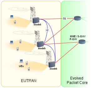
EUTRAN consists only of enodeBs on the network side. The enodeB performs tasks similar to those performed by the nodeBs and RNC (radio network controller) together in UTRAN. The aim of this simplification is to reduce the latency of all radio interface operations. eNodeBs are connected to each other via the X2 interface, and they connect to the packet switched (PS) core network via the S1 interface.[3]
EUTRAN protocol stack

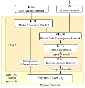
The EUTRAN protocol stack consist of:[3]
- Physical layer:[4] Carries all information from the MAC transport channels over the air interface. Takes care of the link adaptation (ACM), power control, cell search (for initial synchronization and handover purposes) and other measurements (inside the LTE system and between systems) for the RRC layer.
- MAC:[5] The MAC sublayer offers a set of logical channels to the RLC sublayer that it multiplexes into the physical layer transport channels. It also manages the HARQ error correction, handles the prioritization of the logical channels for the same UE and the dynamic scheduling between UEs, etc..
- RLC:[6] It transports the PDCP's PDUs. It can work in 3 different modes depending on the reliability provided. Depending on this mode it can provide: ARQ error correction, segmentation/concatenation of PDUs, reordering for in-sequence delivery, duplicate detection, etc...
- PDCP:[7] For the RRC layer it provides transport of its data with ciphering and integrity protection. And for the IP layer transport of the IP packets, with ROHC header compression, ciphering, and depending on the RLC mode in-sequence delivery, duplicate detection and retransmission of its own SDUs during handover.
- RRC:[8] Between others it takes care of: the broadcast system information related to the access stratum and transport of the non-access stratum (NAS) messages, paging, establishment and release of the RRC connection, security key management, handover, UE measurements related to inter-system (inter-RAT) mobility, QoS, etc..
Interfacing layers to the EUTRAN protocol stack:
Physical layer (L1) design
E-UTRA uses orthogonal frequency-division multiplexing (OFDM), multiple-input multiple-output (MIMO) antenna technology depending on the terminal category and can use as well beamforming for the downlink to support more users, higher data rates and lower processing power required on each handset.[10]
In the uplink LTE uses both OFDMA and a precoded version of OFDM called Single-Carrier Frequency-Division Multiple Access (SC-FDMA) depending on the channel. This is to compensate for a drawback with normal OFDM, which has a very high peak-to-average power ratio (PAPR). High PAPR requires more expensive and inefficient power amplifiers with high requirements on linearity, which increases the cost of the terminal and drains the battery faster. For the uplink, in release 8 and 9 multi user MIMO / Spatial division multiple access (SDMA) is supported; release 10 introduces also SU-MIMO.
In both OFDM and SC-FDMA transmission modes a cyclic prefix is appended to the transmitted symbols. Two different lengths of the cyclic prefix are available to support different channel spreads due to the cell size and propagation environment. These are a normal cyclic prefix of 4.7 μs, and an extended cyclic prefix of 16.6μs.

LTE supports both Frequency-division duplex (FDD) and Time-division duplex (TDD) modes. While FDD makes use of paired spectra for UL and DL transmission separated by a duplex frequency gap, TDD splits one frequency carrier into alternating time periods for transmission from the base station to the terminal and vice versa. Both modes have their own frame structure within LTE and these are aligned with each other meaning that similar hardware can be used in the base stations and terminals to allow for economy of scale. The TDD mode in LTE is aligned with TD-SCDMA as well allowing for coexistence. Single chipsets are available which support both TDD-LTE and FDD-LTE operating modes.
Frames and resource blocks
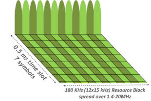
The LTE transmission is structured in the time domain in radio frames. Each of these radio frames is 10 ms long and consists of 10 sub frames of 1 ms each. For non-Multimedia Broadcast Multicast Service (MBMS) subframes, the OFDMA sub-carrier spacing in the frequency domain is 15 kHz. Twelve of these sub-carriers together allocated during a 0.5 ms timeslot are called a resource block.[11] A LTE terminal can be allocated, in the downlink or uplink, a minimum of 2 resources blocks during 1 subframe (1 ms).[12]
Encoding
All L1 transport data is encoded using turbo coding and a contention-free quadratic permutation polynomial (QPP) turbo code internal interleaver.[13] L1 HARQ with 8 (FDD) or up to 15 (TDD) processes is used for the downlink and up to 8 processes for the UL
EUTRAN physical channels and signals
Downlink (DL)
In the downlink there are several physical channels:[14]
- The Physical Downlink Control Channel (PDCCH) carries between others the downlink allocation information, uplink allocation grants for the terminal/UE.
- The Physical Control Format Indicator Channel (PCFICH) used to signal CFI (control format indicator).
- The Physical Hybrid ARQ Indicator Channel (PHICH) used to carry the acknowledges from the uplink transmissions.
- The Physical Downlink Shared Channel (PDSCH) is used for L1 transport data transmission. Supported modulation formats on the PDSCH are QPSK, 16QAM and 64QAM.
- The Physical Multicast Channel (PMCH) is used for broadcast transmission using a Single Frequency Network
- The Physical Broadcast Channel (PBCH) is used to broadcast the basic system information within the cell
And the following signals:
- The synchronization signals (PSS and SSS) are meant for the UE to discover the LTE cell and do the initial synchronization.
- The reference signals (cell specific, MBSFN, and UE specific) are used by the UE to estimate the DL channel.
- Positioning reference signals (PRS), added in release 9, meant to be used by the UE for OTDOA positioning (a type of multilateration)
Uplink (UL)
In the uplink there are three physical channels:
- Physical Random Access Channel (PRACH) is used for initial access and when the UE loses its uplink synchronization,[15]
- Physical Uplink Shared Channel (PUSCH) carries the L1 UL transport data together with control information. Supported modulation formats on the PUSCH are QPSK, 16QAM and depending on the user equipment category 64QAM. PUSCH is the only channel which, because of its greater BW, uses SC-FDMA
- Physical Uplink Control Channel (PUCCH) carries control information. Note that the Uplink control information consists only on DL acknowledges as well as CQI related reports as all the UL coding and allocation parameters are known by the network side and signaled to the UE in the PDCCH.
And the following signals:
- Reference signals (RS) used by the enodeB to estimate the uplink channel to decode the terminal uplink transmission.
- Sounding reference signals (SRS) used by the enodeB to estimate the uplink channel conditions for each user to decide the best uplink scheduling.
User Equipment (UE) categories
3GPP Release 8 defines five LTE user equipment categories depending on maximum peak data rate and MIMO capabilities support. With 3GPP Release 10, which is referred to as LTE Advanced, three new categories have been introduced, and four more with 3GPP Release 11. and two more with 3GPP Release 14.
| User equipment Category |
Max. L1 data rate Downlink (Mbit/s) |
Max. number of DL MIMO layers |
Max. L1 data rate Uplink (Mbit/s) |
3GPP Release |
|---|---|---|---|---|
| NB1 | 0.68 | 1 | 1.0 | Rel 13 |
| M1 | 1.0 | 1 | 1.0 | |
| 0 | 1.0 | 1 | 1.0 | Rel 12 |
| 1 | 10.3 | 1 | 5.2 | Rel 8 |
| 2 | 51.0 | 2 | 25.5 | |
| 3 | 102.0 | 2 | 51.0 | |
| 4 | 150.8 | 2 | 51.0 | |
| 5 | 299.6 | 4 | 75.4 | |
| 6 | 301.5 | 2 or 4 | 51.0 | Rel 10 |
| 7 | 301.5 | 2 or 4 | 102.0 | |
| 8 | 2,998.6 | 8 | 1,497.8 | |
| 9 | 452.2 | 2 or 4 | 51.0 | Rel 11 |
| 10 | 452.2 | 2 or 4 | 102.0 | |
| 11 | 603.0 | 2 or 4 | 51.0 | |
| 12 | 603.0 | 2 or 4 | 102.0 | |
| 13 | 391.7 | 2 or 4 | 150.8 | Rel 12 |
| 14 | 391.7 | 8 | 9,585 | |
| 15 | 750 | 2 or 4 | 226 | |
| 16 | 979 | 2 or 4 | n/a | |
| 17 | 25,065 | 8 | n/a | Rel 13 |
| 18 | 1,174 | 2 or 4 or 8 | n/a | |
| 19 | 1,566 | 2 or 4 or 8 | n/a | |
| 20 | 2,000 | 2 or 4 or 8 | 315 | Rel 14 |
| 21 | 1,400 | 2 or 4 | 300 | Rel 14 |
Note: Maximum data rates shown are for 20 MHz of channel bandwidth. Categories 6 and above include data rates from combining multiple 20 MHz channels. Maximum data rates will be lower if less bandwidth is utilized.
Note: These are L1 transport data rates not including the different protocol layers overhead. Depending on cell bandwidth, cell load (number of simultaneous users), network configuration, the performance of the user equipment used, propagation conditions, etc. practical data rates will vary.
Note: The 3.0 Gbit/s / 1.5 Gbit/s data rate specified as Category 8 is near the peak aggregate data rate for a base station sector. A more realistic maximum data rate for a single user is 1.2 Gbit/s (downlink) and 600 Mbit/s (uplink).[16] Nokia Siemens Networks has demonstrated downlink speeds of 1.4 Gbit/s using 100 MHz of aggregated spectrum.[17]
EUTRAN releases
As the rest of the 3GPP standard parts E-UTRA is structured in releases.
- Release 8, frozen in 2008, specified the first LTE standard
- Release 9, frozen in 2009, included some additions to the physical layer like dual layer (MIMO) beam-forming transmission or positioning support
- Release 10, frozen in 2011, introduces to the standard several LTE Advanced features like carrier aggregation, uplink SU-MIMO or relays, aiming to a considerable L1 peak data rate increase.
All LTE releases have been designed so far keeping backward compatibility in mind. That is, a release 8 compliant terminal will work in a release 10 network, while release 10 terminals would be able to use its extra functionality.
Frequency bands and channel bandwidths
Deployments by region
Technology demos
- In September 2007, NTT Docomo demonstrated E-UTRA data rates of 200 Mbit/s with power consumption below 100 mW during the test.[18]
- In April 2008, LG and Nortel demonstrated E-UTRA data rates of 50 Mbit/s while travelling at 110 km/h.[19]
- February 15, 2008 - Skyworks Solutions has released a front-end module for E-UTRAN.[20][21][22]
See also
References
- 3GPP UMTS Long Term Evolution page
- 3GPP TS 36.306 E-UTRA User Equipment radio access capabilities
- 3GPP TS 36.300 E-UTRA Overall description
- 3GPP TS 36.201 E-UTRA: LTE physical layer; General description
- 3GPP TS 36.321 E-UTRA: Access Control (MAC) protocol specification
- 3GPP TS 36.322 E-UTRA: Radio Link Control (RLC) protocol specification
- 3GPP TS 36.323 E-UTRA: Packet Data Convergence Protocol (PDCP) specification
- 3GPP TS 36.331 E-UTRA: Radio Resource Control (RRC) protocol specification
- 3GPP TS 24.301 Non-Access-Stratum (NAS) protocol for Evolved Packet System (EPS); Stage 3
- "3GPP LTE: Introducing Single-Carrier FDMA" (PDF). Retrieved 2018-09-20.
- TS 36.211 rel.11, LTE, Evolved Universal Terrestrial Radio Access, Physical channels and modulation - chapters 5.2.3 and 6.2.3: Resource blocks etsi.org, January 2014
- LTE Frame Structure and Resource Block Architecture Teletopix.org, retrieved in August 2014.
- 3GPP TS 36.212 E-UTRA Multiplexing and channel coding
- 3GPP TS 36.211 E-UTRA Physical channels and modulation
- "Nomor Research Newsletter: LTE Random Access Channel". Archived from the original on 2011-07-19. Retrieved 2010-07-20.
- "3GPP LTE / LTE-A Standardization: Status and Overview of Technologie, slide 16" (PDF). Archived from the original (PDF) on 2016-12-29. Retrieved 2011-08-15.
- "4G speed record smashed with 1.4 Gigabits-per-second mobile call #MWC12 | Nokia". Nokia. Retrieved 2017-06-20.
- NTT DoCoMo develops low power chip for 3G LTE handsets Archived September 27, 2011, at the Wayback Machine
- "Nortel and LG Electronics Demo LTE at CTIA and with High Vehicle Speeds". Archived from the original on June 6, 2008. Retrieved 2008-05-23.
- "Skyworks Rolls Out Front-End Module for 3.9G Wireless Applications. (Skyworks Solutions Inc.)" (free registration required). Wireless News. February 14, 2008. Retrieved 2008-09-14.
- "Wireless News Briefs - February 15, 2008". WirelessWeek. February 15, 2008. Retrieved 2008-09-14.
- "Skyworks Introduces Industry's First Front-End Module for 3.9G Wireless Applications". Skyworks press release. Free with registration. 11 Feb 2008. Retrieved 2008-09-14.
