Distributed propulsion
Distributed propulsion (DP) is a type of flight propulsion system in which thrust is delivered by several propulsors arranged on the aircraft. Its goal is to increase performance in fuel efficiency, emissions, noise, landing distance and manoeuvrability. DP is typically accomplished by spanwise distribution of partially or fully embedded multiple small engines or fans along the wing. Alternatively, it may involve ducting exhaust gases along the wing's entire trailing edge.
- For distributed propulsion on railway trains see: Multiple unit
Definition
A simple definition of DP can be described as a propulsion system where the vehicle thrust is produced from an array of propulsors located across the air vehicle. While a formal definition of a DP system has not yet been established,in general the distributed thrust capabilities of a DP system should serve an enabling role in improving the system-level efficiency, capabilities, or performance of the air vehicle. Otherwise, any aircraft with more than one propulsor could be classified as such.[1]
Technologies
The Distributed Propulsion concept has been applied in aviation around 4 main technologies :
Jet-Flap / Distributed Jet
In this configuration, a high velocity jet flow is injected at the trailing edge of the wing to increase lift at low speed (see: blown flaps) or increase cruising performance (see : Lockheed F-117 Nighthawk ). This airflow is commonly extracted from the main jet engine of the aircraft and redirected to several exits along the wing.
Independent Propulsors Distribution
This distribution uses independent thrusters units, i.e. each propulsors can be controlled independently of the others, and its engine is directly supplied with fuel without intermediaries: no generator, no turbine, etc.
Non-Independent Propulsors Distribution
This distribution uses mutually dependent thrusters units, i.e. each propulsors is connected to a central engine that receives the throttle control, provides the mechanical energy needed by the propulsors and serves at least 2 of them.
For instance, the Wright brothers were using chains to distribute the power from their combustion engine to the 2 propellers on their Wright Flyer. The SAX-40 aircraft is a more recent project including non-independent propulsors, the 3 separates fans are powered by one motor unit.
Distributed Electric Propulsion (DEP)
The propulsors do not share a common mechanical driveshaft or mechanical power source with the power-producing components of the system. Instead, the power sources can be any combination of electrical power-producing devices (electric generator, fuel cell, etc) and energy storage devices (battery, capacitor, etc), while the propulsors can be any combination of thrust producing devices such as electrically-driven propellers or fans.[1]
Additional features
Recent analytic and experimental distributed propulsion studies suggest several improvements in aircraft performance :[2]
Global Improvements
- Increase Fuel efficiency
- Reduce emissions
- Noise reduction
- Cheaper to manufacture [3]
- Low operational cost
- Improve Vehicle control, vectored thrust
- Allow VTOL (Vertical Take-Off and Landing) or STOL (Short Take-Off and Landing)
- Scalability : concept of Scalable 3D Distributed Propulsion [4]
Security Advantages
- Redundancy, in case of an engine failure the others can maintain safe flight conditions. [5]
- Makes it easier to change a failed propulsor.
Aerodynamic Progress [6]
- Direct reenergizing of the boundary layer
- Flow separation control
- Powered lift/circulation control
- Viscous drag reduction
- Vortex/vorticity control
Aircraft designs
Fixed-wing Aircraft
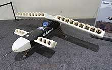
These implementations are often proposed in conjunction with blended wing body (BWB) or hybrid wing body (HWB) aircraft. While some of these concepts were tested on full scale aircraft in the 1960–70s, such as the Hunting H.126, they were not fielded in production aircraft. More recently, several full-size and smaller unmanned aerial vehicle (UAV) projects have proposed DP approaches to meet noise abatement, fuel efficiency and landing field length goals. Advancements in materials engineering, cryogenic cooling systems, novel fuels and high fidelity computational fluid dynamics (CFD) modeling and analysis have been credited for the renewed interest.
Multi-copter
Since flight controllers (Pixhawk) were invented, distributed propulsion has had new applications, including multirotor propulsion. Multirotors are vehicles capable of flying by means of several thrusters that generate vertical thrust. Rotors are controlled by the flight controller which integrated the formula of DEP.[7] The common architectures of these aircraft are tricopter (3 motors), quadcopter (4 motors), hexacopter (6 motors) and octocopter (8 motors)[8].
Classification
Researchers have tried to propose a classification of such a propulsion system. Note : it's a non official classification.
DP Configuration[6]
- Leader configuration (L) : all the propulsion units solely contribute to the propulsion thrust without driving a secondary propulsion unit.
- Follower configuration (F) : at least one propulsion unit is used as a secondary propulsion unit. This could for instance refer to a gas turbine arrangement where a power generator drives one or a multiple of fans.
Intensity classes[6]
Intensity classes group designs according to the number of propulsion units they employ.
| Distributed propulsion intensity classes | A | B | C | D | E |
|---|---|---|---|---|---|
| Number of propulsion units | 3 | 4-6 | 7-10 | 11-20 | 20< |
Thrust-to-weight ratios[6]
For distributed propulsion, this ratio can be defined as the total aircraft thrust produced divided by the Maximum Take-Off Weight (MTOW) rather than dividing only by the propulsion unit weight, given the strategy's potential to reduce the weight of the rest of the aircraft.
| Thrust-to-weight ratio intensity classes | I | II | III |
|---|---|---|---|
| Thrust-to-weight ratio based on MTOW | <0.10 | 0.10 to <0.15 | 0.15< |
Example
Thus, the following convention describes specific systems:
DP Configuration (L/F)-Intensity class (A-E)-Thrust-to-weight (I-III)-(X)
For example, the 1945s Blohm and Voss 238 V1 aircraft would be denoted as DPL-B-I,since the aircraft employs six piston engines and has a thrust-to-weight ratio less than 0.10.
See also
- NASA X-57 Maxwell
- Moller M400 Skycar
- Airbus Vahana
- Blended wing body
- Multirotor
References
- A Review of Distributed Electric Propulsion Concepts for Air Vehicle Technology (PDF) (Report). NASA. 2020-06-22.
- Epstein, A. 'Distributed Propulsion: New Opportunities For An Old Concept'. Report (2007)
- Kim, Hyun Dae, ‘Distributed Propulsion Vehicles’, in 27th International Congress of the Aeronautical Sciences, 2011, pp. 1–11.
- , "Electric VTOL aircraft", issued 2010-03-22
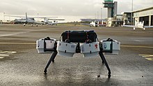
- Mortimer, Gary (2017-03-28). "Neva Aerospace project opens doors for development of aerial robots". sUAS News - The Business of Drones. Retrieved 2020-07-30.
- Gohardani, A.S. 'A synergistic glance at the prospects of distributed propulsion technology and the electric aircraft concept for future unmanned air vehicles and commercial/military aviation', Progress in Aerospace Sciences, Volume 57, February 2013, Pages 25-70:
- Saengphet, Watcharapol & Tantrairatn, Suradet & Thumthae, Chalothorn & Srisertpol, Jiraphon. (2017). Implementation of system identification and flight control system for UAV. 678-683. 10.1109/ICCAR.2017.7942783.
- "Connect ESCs and Motors — Copter documentation". ardupilot.org. Retrieved 2020-07-29.