Deaerator
A deaerator is a device that removes oxygen and other dissolved gases from liquids. Deaerators are commonly used to remove dissolved gases in feedwater for steam-generating boilers. Dissolved oxygen in feedwater will cause serious corrosion damage in a boiler by attaching to the walls of metal piping and other equipment and forming oxides (like rust). Dissolved carbon dioxide combines with water to form carbonic acid that may cause further corrosion. Most deaerators are designed to remove oxygen down to levels of 7 ppb by weight or less, as well as essentially eliminating carbon dioxide.[1][2] The deaerators in the steam generating systems of most thermal power plants use low pressure steam obtained from an extraction point in their steam turbine system. However, the steam generators in many large industrial facilities such as petroleum refineries may use whatever low-pressure steam is available.
Deaerators are also used to remove dissolved gases from products such as food, personal care products, cosmetic products, chemicals, and pharmaceuticals to increase the dosing accuracy in the filling process, to increase product shelf stability, to prevent oxidative effects (e.g. discolouration, changes of smell or taste, rancidity), to alter pH, and to reduce packaging volume.
Types
There are many different deaerators available from a number of manufacturers, and the actual construction details will vary from one manufacturer to another.
There are these basic types of deaerators:[3][4][5]
- The thermal deaerators
- The spray & tray-type (also called the cascade-type) includes a vertical or horizontal domed deaeration section mounted on top of a horizontal cylindrical vessel which serves as the deaerated boiler feedwater storage tank.
- The spray-type consists only of a horizontal (or vertical) cylindrical vessel which serves as both the deaeration section, and a storage tank for boiler feedwater.
- The vacuum rotating disc deaerators for low to high viscous products
- The ultrasound deaerator for very viscous products
Figures 1 and 2 are representative schematic diagrams that depict each of the two major types of deaerators.
Spray and tray-type deaerator
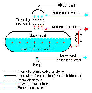
The typical spray & tray-type deaerator in Figure 1 has a vertical domed deaeration section mounted above a horizontal boiler feedwater storage vessel. Boiler feedwater enters the vertical deaeration section through spray valves above the perforated trays and then flows downward through the perforations. Low-pressure deaeration steam enters below the perforated trays and flows upward through the perforations. Combined action of spray valves & trays guarantees very high performance because of longer contact time between steam and water.[6] Some designs use various types of packed beds, rather than perforated trays, to provide good contact and mixing between the steam and the boiler feed water.
The steam strips the dissolved gas from the boiler feedwater and exits via the vent valve at the top of the domed section. Should this vent valve not be opened sufficiently the deaerator will not work properly, causing high oxygen content in the feed water going to the boilers. Should the boiler not have an oxygen-content analyser, a high level in the boiler chlorides may indicate the vent valve not being far enough open. Some designs may include a vent condenser to trap and recover any water entrained in the vented gas. The vent line usually includes a valve and just enough steam is allowed to escape with the vented gases to provide a small visible telltale plume of steam.
The deaerated water flows down into the horizontal storage vessel from where it is pumped to the steam generating boiler system. Low-pressure heating steam, which enters the horizontal vessel through a sparge pipe in the bottom of the vessel, is provided to keep the stored boiler feedwater warm. External insulation of the vessel is typically provided to minimize heat loss.
Spray-type deaerator
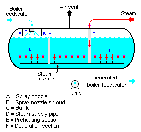
As shown in Figure 2, the typical spray-type deaerator is a horizontal vessel which has a preheating section (E) and a deaeration section (F). The two sections are separated by a baffle (C). Low-pressure steam enters the vessel through a sparger in the bottom of the vessel.
The boiler feedwater is sprayed into section (E) where it is preheated by the rising steam from the sparger. The purpose of the feedwater spray nozzle (A) and the preheat section is to heat the boiler feedwater to its saturation temperature to facilitate stripping out the dissolved gases in the following deaeration section.
The preheated feedwater then flows into the deaeration section (F), where it is deaerated by the steam rising from the sparger system. The gases stripped out of the water exit via the vent at the top of the vessel. Again, some designs may include a vent condenser to trap and recover any water entrained in the vented gas. Also again, the vent line usually includes a valve and just enough steam is allowed to escape with the vented gases to provide a small and visible telltale plume of steam.
The deaerated boiler feedwater is pumped from the bottom of the vessel to the steam generating boiler system.
Vacuum rotating disc type deaerator
As shown in Figure 3, the product is distributed as a thin layer on a high speed spinning disc [3] via special feed system [1]. The centrifugal force slings it through a perforated screen onto the inner wall of the vessel, which is under vacuum . Air (gas) pockets are released in the process and are drawn off by the vacuum [4]. A discharge pump [2] carries the deaerated product to the next process in the production line. For high viscous products the rotating disc is replaced with static one.

Principles of operation
Deaeration relies on the principle that the solubility of a gas in water decreases as the water temperature increases and approaches its boiling point. In the deaerator, water is heated up to close to its boiling point with a minimum pressure drop and minimum vent. Deaeration is done by spraying feedwater into a chamber to increase its surface area, and may involve flow over multiple layers of trays. This scrubbing (or stripping) steam is fed to the bottom of the deaeration section of the deaerator. When steam contacts the feedwater, it heats it up to its boiling point and dissolved gases are released from the feedwater and vented from the deaerator through the vent. The treated water falls into a storage tank below the deaerator.[7][1]
Oxygen scavenging
Oxygen scavenging chemicals are very often added to the deaerated boiler feedwater to remove any last traces of oxygen that were not removed by the deaerator. The type of chemical added depends on whether the location uses a volatile or non-volatile water treatment program.
Most lower pressure systems (lower than 650 psi (4,500 kPa)) use non-volatile treatment programs. The most commonly used oxygen scavenger for lower pressure systems is sodium sulfite (Na2SO3). It is very effective and rapidly reacts with traces of oxygen to form sodium sulfate (Na2SO4) which is non-scaling.
Most higher pressure systems (higher than 650 psi (4,500 kPa)) and all systems where certain highly alloyed materials are present are now using volatile programs, as many phosphate-based treatment programs are being phased out. Volatile programs are further broken down into oxidizing or reducing programs [(AVT(O) or AVT(R)] depending whether the environment requires an oxidizing or reducing environment to reduce the incidence of flow-accelerated corrosion. Flow-accelerated corrosion related failures have caused numerous accidents in which significant loss of property and life has occurred. Hydrazine (N2H4) is an oxygen scavenger commonly used in volatile treatment programs.
Other scavengers include carbohydrazide, diethylhydroxylamine, nitrilotriacetic acid, ethylenediaminetetraacetic acid, and hydroquinone.
See also
- Air preheater
- Economizer
- Feedwater heater
- Fossil fuel power plant
- Thermal power station
- Degasification
- Defoamer
References
Citations
- "The Deaerating Principle". Sterling Deaerator Company.
- "Deaerators". Stork. Archived from the original on 2018-09-01. Retrieved 2016-09-30.
- Kent 1936.
- Babcock & Wilcox Co. 2005.
- Elliott, Chen & Swanekamp 1998, pp. 167-, Ch. 2.
- Standards and Typical Specifications for Tray Type Deaerators (10th ed.). Heat Exchange Institute. November 2016.
- "Deaerator working principle". Boilers Info.
Sources
- Babcock & Wilcox Co. (2005). Steam: Its Generation and Use (41st ed.). ISBN 0-9634570-0-4.CS1 maint: ref=harv (link)
- Elliott, Thomas C.; Chen, Kao; Swanekamp, Robert (1998). Standard Handbook of Powerplant Engineering (2nd ed.). McGraw-Hill. ISBN 978-0-07-019435-9.CS1 maint: ref=harv (link)
- Kent, Robert Thurston, ed. (1936). Kents' Mechanical Engineers' Handbook in two volumes (11th ed.). John Wiley & Sons.CS1 maint: ref=harv (link)