Croton Dam (Michigan)
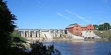
Croton Dam (or Croton Hydroelectric Plant) is an earth-filled embankment dam and powerplant complex on the Muskegon River in Croton Township, Newaygo County, Michigan. It was built in 1907 under the direction of William D. Fargo by the Grand Rapids - Muskegon Power Company, a predecessor of Consumers Energy.[3][4] The 40-foot-high (12 m) dam impounds 7.2 billion U.S. gallons (6 billion imp. gal/27 billion L) of water in its 1,209-acre (489 ha) reservoir and is capable of producing 8,850 kilowatts at peak outflow.[5][6] It was listed on the National Register of Historic Places in 1979.[3]
| Croton Dam | |
|---|---|
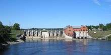 Croton Dam and Hydroelectric Plant | |
| Official name | Croton Hydroelectric Plant |
| Country | United States |
| Location | Croton Township, Newaygo County, Michigan |
| Coordinates | 43°26′14″N 85°39′50″W |
| Purpose | Power |
| Status | Operational |
| Construction began | 25 June 1907 |
| Opening date | 3 September 1907 |
| Owner(s) | Consumers Energy |
| Dam and spillways | |
| Type of dam | Embankment, earth-fill |
| Impounds | Muskegon River |
| Height | 40 ft (12 m) |
| Length | 370 ft (113 m) |
| Width (crest) | 20 ft (6 m) |
| Width (base) | 800 ft (244 m) |
| Dam volume | 104,000 cu yd (79,514 m3)[1] |
| Reservoir | |
| Creates | Croton Reservoir |
| Total capacity | 22,095-acre-foot (27,253,781 m3) |
| Surface area | 1,209-acre (489 ha) |
| Power Station | |
| Commission date | 1907/1915 |
| Type | Run-of-the-river |
| Turbines | 2 x 4.4 MW Francis-type[2] |
| Installed capacity | 8.85 MW |
Croton Hydroelectric Plant | |
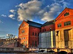 Croton Dam powerhouse from SE downstream side | |
 Location within the state of Michigan 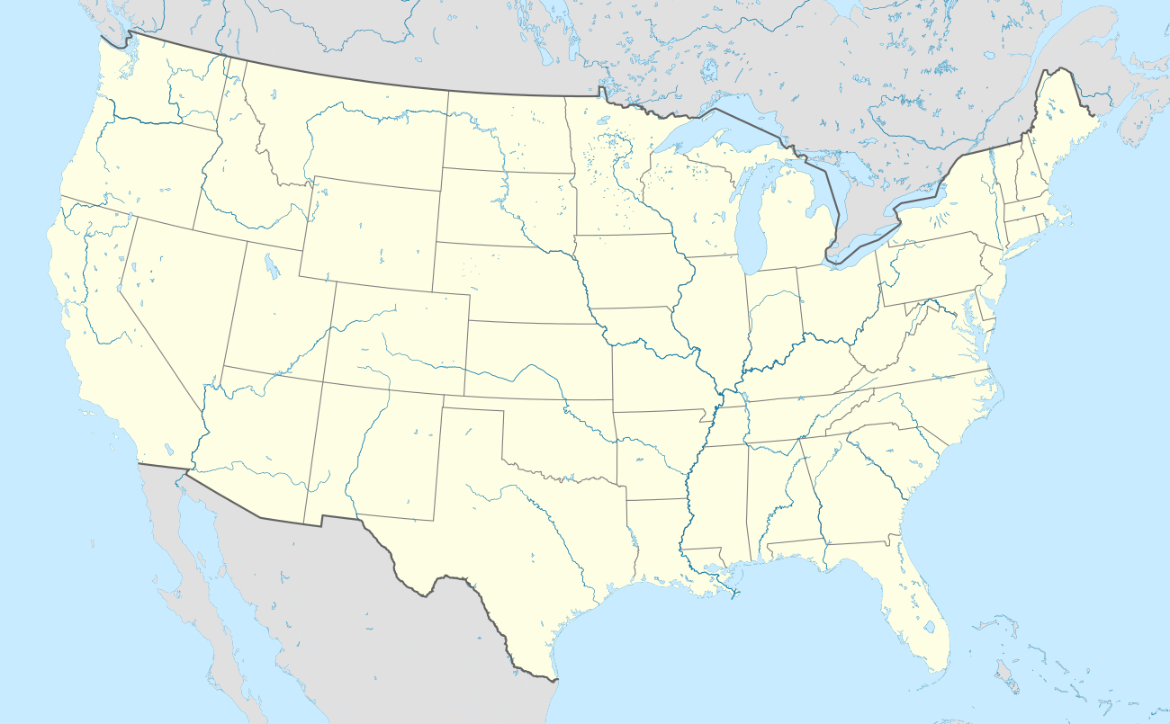 Croton Dam (Michigan) (the United States) | |
| Architect | William D. Fargo |
| NRHP reference No. | 79001165[3] |
| Significant dates | |
| Added to NRHP | August 8, 1979 |
| Designated MSHS | August 16, 1979 |
History
The history of the Croton dam is intertwined with the history of William A. Foote (1854–1915) and James B. Foote (1867–1924), brothers from Adrian, Michigan, with a burgeoning electric power empire, along with William G. Fargo, a Jackson-based civil engineer who designed similar hydroelectric plants throughout the Midwest.[1][7]
William A. Foote was a 30-year-old grist mill operator in Adrian, Michigan, in 1884 when, in what was then a common occurrence, he provided space and shaft power from his mill wheel to Thomson - Houston, a local electric utility startup, to light 12 streetlights. Fascinated by the potential, within a year he enlisted his then 17-year-old brother James and moved to Jackson, Michigan, and in 1886 they jointly founded Jackson Electric Light Works (a predecessor company to Consumers Energy), which began by lighting downtown Jackson electrically.[8] The Foote brothers set up similar city specific companies in Battle Creek and Adrian within a few years. In many cases dams already built for grist mills, sawmills and the like were refit for electric generators, but in some cases, new dams were constructed. As the familiarity with the technology, and the technology itself, improved, the scope of projects became more ambitious.
Predecessor projects
The Foote brothers' first projects in Jackson, Battle Creek and Adrian, like most pre-1900 electric power projects, were created for street lighting, with some limited residential and business lighting. Since transmission of electricity over long distances was not well understood, they were situated near the cities they served. But the demand for power was growing, driven by among other things, the advent of the streetcar and increased industrial use of electricity, outstripping the capacity of smaller rivers and existing dams. So larger rivers were sought. In 1898 the Foote brothers, working with engineering partner Fargo, constructed the Trowbridge Dam across the Kalamazoo River in order to supply the city of Kalamazoo.[7] The dam was located near Allegan, about 25 miles (40 km) away from the city, an unheard of distance at the time, and was the first major hydroelectric project in Western Michigan.[7][9] Initially beset by power loss during transmission and other problems, the Trowbridge dam successfully provided power to a larger area than previous dams, after the Foote brothers advanced the state of the art in insulators and electric transmission equipment.[9]
Damming the Muskegon
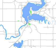
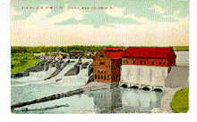
Grand Rapids was a large power market to which the Footes next turned their attention. Fargo advised the Foote brothers about possible hydropower locations on the Muskegon River, which has the second largest outflow of an inland (non Great Lakes connecting) river of Michigan after the Grand River (which has a larger basin and the largest outflow of Michigan's inland rivers).[10][11] Unlike the Grand, the Muskegon is not navigable, so dams would not cause difficulty with river traffic. Through a subsidiary of their holding company, Commonwealth Power, the Grand Rapids – Muskegon Power Company, in 1904 they commissioned the construction of Rogers Dam and Croton Dam on the Muskegon, as well as Webber Dam on the Grand River.[12] Rogers, upstream of the Croton, was finished first, in 1906, but Croton, located where the Little Muskegon joins from the east, was a more ambitious project. One third of the village of Croton would be submerged by the impoundment lake as it began filling in August 1907.[4] William D. Fargo was dispatched to oversee construction and served as the Chief Engineer.[3]
Construction
Fargo developed new methods for construction of earth embankment dams on foundations of soft soils, which made use of hydraulic sluicing. The dam was built during the summer, between 25 June and 3 September 1907. The powerhouse and spillway sections of the dam were completed first, and used conventional contemporary engineering designs.[1][13]
Fargo then built a pumping plant employing seven electric powered rotary pumps, to move river water up a 10-inch (250 mm) pipeline to a bluff about 110 feet (34 m) above the Muskegon River. A diameter reduction to 4 inches (100 mm) increased the pressure to about 80 PSI, and the water was fed into nozzles via flexible rubber hoses. The high pressure streams of water carried away a soil water mix into iron troughs which routed the material about 800 feet (240 m) at a slight downgrade back to the dam site. As the material was deposited it was layered, and the water allowed to drain off, compacting it. During this phase, the river was allowed to run through the powerhouse raceways and out the spillway.[1][13]
The Croton Dam is one of the earliest examples of the use of this technique east of the Mississippi River. The chief advantage of the hydraulic sluicing method was its cost. The total cost of constructing the 370-foot-long (110 m) embankment, which contained 104,000 cubic yards (80,000 m3) of material, was only $7,076, or about 7 cents per cubic yard of material moved. Fargo also used this method to construct a fill of 20,000 cubic yards (15,000 m3) for a highway bridge crossing the Muskegon River immediately downstream from the dam. The fill Fargo built for the highway bridge approach cost roughly the same.[1][13]
The Croton powerhouse has two adjoining asymmetrically connected buildings: the generator building on the west and the turbine building to the east arranged in an L shape. About 3,000 oak timber pilings support a concrete foundation, with the perimeter walls supported on sheet steel pilings, which also prevent water from undercutting the foundation. The two buildings are about 60 feet (18 m) in height, with Warren trusses supporting the roofs, and extend about 150 by 80 feet (46 by 24 m).[14]
Two reinforced concrete retaining walls extend 40 feet (12 m) upstream from the northeast and northwest corners of the generator building, forming a triangle and serve as an anchor for a floating trash boom which keeps refuse out of the turbine pits. A similar triangle is formed by two reinforced concrete retaining walls extending 50 feet (15 m) downriver from the south side of the generator building. A concrete retaining wall extends an additional 140 feet (43 m) south from the tip of this triangle.[14]
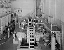
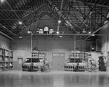
When the generator building first went into operation, it housed two Westinghouse horizontal generators originally rated at 6,600 volts, operating at 225 rpm and producing 3 phase 60 cycle AC. They were driven by turbines. The voltage was stepped up to 100,000 volts using three delta-connected oil-cooled transformers of 3,000 kilowatt capacity. These were regulated with oil switches, and the transformers and switch gear were housed in the south end of the generator building.[14]
The Croton Dam and hydro plant were completed in 1907, and a grand opening was held on September 7, 1907 in the village (named after Croton-on-Hudson, New York).[12] Contemporary accounts report that "Grand Rapids Mayor George Ellis and a large contingent of city and business officials journeyed north to the village of Croton on a special train. After touring the big dam, they adjourned to a nearby field for a fine dinner, followed by cigars and a friendly baseball game."[4]
In order to achieve efficient power transmission over 50 miles (80 km) to Grand Rapids, a 100,000-volt high voltage line was built, then the highest-voltage transmission line in the world. Dr. Charles Steinmetz, the "wizard" of General Electric, visited the site and conducted tests on the transmission lines in 1908.[6] The line voltage was increased to 110,000 volts in early 1909.[14]
Modifications
A significant revamping and expansion of generating capacity was carried out in 1915. Additional turbines and generators were added, blurring the distinction between the buildings. The generator building got pairs of Allis-Chalmers quadriplex horizontal turbines to drive the Westinghouse horizontal generators. Each pair of turbines is rated at 4,000 horsepower when operated at 225 RPM with a hydraulic head of 39 feet (12 m). The operating voltage of the two original Westinghouse horizontal generators was raised to 7,500 volts, with a corresponding increase in the line voltage from 110,000 to 115,000 volts.[14]
The turbine building was modified to take more equipment, resulting in a rearrangement of the walls to enlarge it and addition of a gable to it, similar in appearance to that on the generator building. It has a much higher floor than the generator building and received a pair of vertical turbine/generator sets.[14]
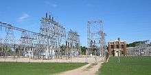
The transformers and switching equipment were removed from the generator building in 1930, when a separate switchyard/substation went into service to the west of the spillway.[14] Shortly thereafter, in 1931, Croton and Rogers dams were joined by the Hardy Dam, situated between them. The Hardy was the last major hydroelectric project constructed in Michigan by Consumers Energy.[7] Once completed, the 40-foot (12 m)-high dam would later impound 7.2 billion U.S. gallons (6 billion imp. gal/27 billion L) of water in its 1,209-acre (489 ha) reservoir and is capable of producing 8850 kilowatts at peak outflow.[5][6]
Legacy
A historical marker sign was placed at the Croton Dam, after its completion. It read:
The Grand Rapids - Muskegon Power Company (a predecessor to today's Consumers Energy Company) built the Croton Hydroelectric Plant in 1906 - 1907. The plant and its 110,000-volt transmission line (the highest voltage in use at that time) attracted international attention. Curious spectators rode excursion trains to the site, where they received a tour of the dam and powerhouse, as well as a grand dinner. When the plant went into full service in September 1907 it represented the latest advances in electric power generation and transmission. Engineers from Russia, England, France, Italy, Japan, and India came to tour the plant when it opened. The facility is listed in the National Register of Historic Places.[15]
The Croton Hydroelectric Plant was listed with the Michigan State Register and was awarded a Michigan Historical Marker (site S0684). The marker was replaced with a new one in 2005.[15] The site was then listed with the National Register of Historic Places in 1979 as structure ID #79001165.[3]
Impact and controversy
While Croton advanced the state of the art in hydroelectric engineering, it also submerged significant sections of scenic and fast-flowing stretches of the Muskegon and Little Muskegon rivers.[5] Some conservationists believe that Croton Dam and the other dams on the Muskegon divide the 219-mile (352 km) long river into shorter, ecologically dysfunctional units.[5] It blocks passage of fish from one river section to the next. It allegedly causes potentially harmful changes in water temperature and oxygen levels in a stretch of the river downstream of the dam, according to company data.[5]
The dam was threatened by rainfall during the flood of September 1986. The Croton and Hardy nearly failed during the peak of the flood, caused by a storm that dumped 14 inches (36 cm) of rain on West Michigan in 48 hours. Consumers Energy officials stated that "had the Hardy Dam failed, the Croton Dam would have been washed away and every community from Croton to Muskegon would have been submerged under several feet of water".[5]
Subsequently, in 1989, Michigan state fisheries director John Robertson characterized hydroelectric dams as "concrete and steel monsters" and suggested 11 Consumers Energy dams be removed from the Muskegon, Manistee and AuSable rivers.[5] Local officials then gathered petition signatures from 14,000 people who supported keeping the dams.[5] The federal government has relicensed the dams through 2034, but has required operating changes reducing their harmful effects on the Muskegon River.[5]
Current status
The Croton Dam and hydroelectric plant is owned and operated by Consumers Energy, an electric power company headquartered in Jackson, Michigan. Croton generated 44 million kilowatt hours of electricity in 2006, which would satisfy the annual electric consumption of about 6,000 residential customers.[4]
The three dams, Rogers, Hardy, and Croton (all owned and operated by Consumers Energy), are operated in different modes but in concert give a net run of river effect on water flow. The Rogers itself has little or no impoundment and runs in run of river mode, passing through as much water as it receives. The Croton and Hardy work in concert. The Hardy, which has a larger capacity reservoir, larger turbines, and is upstream of the Croton, runs in full peaking mode, meaning that the river flow is impounded and used to generate electricity during peak demand periods. This causes wide fluctuations in water flows and reservoir levels, typically with low outflow during the night when power demand is lowest. Full peaking was once very common but because of the outflow fluctuations, is now less common. However, with the Croton immediately downstream, and with no river segment (the Croton impoundment stretches back to the Hardy outlet), it can be run in re-regulation mode, allowing a natural flow rate to exit. The Croton reservoir level fluctuates inversely with the Hardy, rising during the day and lowering at night. Since the Hardy reservoir is so large, its reservoir level fluctuates about 4 inches (10 cm) in total, while the Croton reservoir fluctuates about 9 inches (23 cm). During the winter and spring runoff, the Hardy is allowed to fluctuate much more. It can be drawn down up to 12 feet (4 m) to meet winter power demand but is required to return to normal levels by the end of April each spring.[16]
Together, the three dams (Rogers, Hardy and Croton) can generate about 45,500 kilowatts, with about 30,000 of that from the Hardy.[6]
See also
- Croton Township, Michigan where the dam is located
- Big Rapids, Michigan the nearest major city
- List of Registered Historic Places in Newaygo County, Michigan
- New Croton Dam which is in Croton-On-Hudson, New York
References
- Hyde, Dr. Charles K. (October 1994). "Historic American Engineering Record, CROTON HYDROELECTRIC PLANT, DAM" (PDF). National Park Service. Archived from the original (PDF) on 2011-06-04. Retrieved 2008-06-11.
- Hyde, Dr. Charles K. (May 1994). "Historic American Engineering Record, CROTON HYDROELECTRIC PLANT, POWERHOUSE" (PDF). National Park Service. Retrieved 2015-01-01.
- "National Register Information System". National Register of Historic Places. National Park Service. July 9, 2010.
- "Croton Dam 1907-2007 Centennial Celebration brochure" (PDF). Archived from the original (PDF) on 2007-09-27. Retrieved 2008-06-11.
- Jeff Alexander. "Historic Croton Dam changed West Michigan". Muskegon Chronicle on mlive.com. Retrieved 2008-06-11. External link in
|work=(help) - "Muskegon River Hydroelectric Resources". Consumers Energy website. Archived from the original on 2007-09-27. Retrieved 2008-06-11. External link in
|work=(help) - "Hydroelectric Power in Michigan - The Consumers Energy Story, and The Lyons Connection" (PDF). Archived from the original (PDF) on September 28, 2007. Retrieved 2008-06-11.
- Michael W. Panhorst. "Lorado Taft, William A. Foote Memorial". Outdoor Sculpture in Jackson, Michigan at Ella Sharpe Museum site. Archived from the original on 2008-05-18. Retrieved 2008-06-11. External link in
|work=(help) - "Consumers Power Co. company history". answers.com site. Retrieved 2008-06-11. External link in
|work=(help) - "Hydrology: Rivers of Michigan". Archived from the original on 2005-04-22. Retrieved 2008-06-11.
- An image of Michigan's inland drainage basins is here
- "The sunken village under Croton Pond". Archived from the original on 2010-10-23. Retrieved 2008-06-11.
- Fargo, William G. (24 October 1907). "Hydraulic Excavation and Dam Building at the Croton and Lyons Dams in Michigan". Engineering News. 58 (17): 429–431.
- Hyde, Charles K. (1994). "Croton Hydroelectric Plant, Powerhouse" (PDF). Historic American Engineering Record. Washington, D.C.: Library of Congress. Archived from the original (PDF) on October 22, 2012. Retrieved February 27, 2014.
- text of marker, marker data from "Croton Hydroelectric Plant page". Michigan Historical Markers site. Retrieved 2008-06-11.
- "Balancing Flows and Power Production along the Muskegon River" (PDF). 2005 Hydro Reporter, pages 9 and 11, found embedded in the Michigan Hydro History PDF. Archived from the original (PDF) on June 14, 2006. Retrieved September 7, 2007.
External links
| Wikimedia Commons has media related to Croton Dam (Michigan). |
- Image while under construction from Consumers Energy site
- Park and Recreational information from the Michigan Department of Natural Resources
- Fisheries information from the Michigan Department of Natural Resources
- Dam impact study from the city of Big Rapids, Michigan
- Croton-Hardy Business Alliance
- Historic American Engineering Record (HAER) No. MI-81, "Croton Hydroelectric Plant, Croton Dam Road at Muskegon River, Croton, Newaygo County, MI"
- HAER No. MI-81-A, "Croton Hydroelectric Plant, Dam"
- HAER No. MI-81-B, "Croton Hydroelectric Plant, Powerhouse"
- HAER No. MI-81-C, "Croton Hydroelectric Plant, Spillway"
- HAER No. MI-81-D, "Croton Hydroelectric Plant, Substation"
- Croton Dam at Structurae

