Chronoamperometry
Chronoamperometry is an electrochemical technique in which the potential of the working electrode is stepped and the resulting current from faradaic processes occurring at the electrode (caused by the potential step) is monitored as a function of time. The functional relationship between current response and time is measured after applying single or double potential step to the working electrode of the electrochemical system. Limited information about the identity of the electrolyzed species can be obtained from the ratio of the peak oxidation current versus the peak reduction current. However, as with all pulsed techniques, chronoamperometry generates high charging currents, which decay exponentially with time as any RC circuit. The Faradaic current - which is due to electron transfer events and is most often the current component of interest - decays as described in the Cottrell equation. In most electrochemical cells this decay is much slower than the charging decay-cells with no supporting electrolyte are notable exceptions. Most commonly a three electrode system is used. Since the current is integrated over relatively longer time intervals, chronoamperometry gives a better signal to noise ratio in comparison to other amperometric techniques.
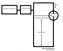
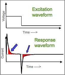
[1][2][3] There are two types of chronoamperometry that are commonly used, controlled-potential chronoamperometry and controlled-current chronoamperometry. Before running controlled-potential chronoamperometry, cyclic voltametries are run to determine the reduction potential of the analytes. Generally, chronoamperometry uses fixed area electrodes, which is suitable for studying electrode processes of coupled chemical reactions, especially the reaction mechanism of organic electrochemistry.[4]
Example
Anthracene in deoxygenated dimethylformamide (DMF) will be reduced (An + e− -> An−) at the electrode surface that is at a certain negative potential. The reduction will be diffusion-limited, thereby causing the current to drop in time (proportional to the diffusion gradient that is formed by diffusion).
You can do this experiment several times increasing electrode potentials from low to high. (In between the experiments, the solution should be stirred.) When you measure the current i(t) at a certain fixed time point τ after applying the voltage, you will see that at a certain moment the current i(τ) does not rise anymore; you have reached the mass-transfer-limited region. This means that anthracene arrives as fast as diffusion can bring it to the electrode.
History
In 1902, F.G. Cottrell deduced the linear diffusion on a planar electrode according to the diffusion law and Laplace transformation, and obtained the Cottrell equation: , where i is the current in A, n is the number of electrons, F is Faraday constant, A is the area of the planar electrode in cm2, C0 is the initial concentration of the analyte in mol/cm3. D is the diffusion coefficient for species in cm2/s, t is the time in s. Under controlled-diffusion circumstances, the current-time plot reflects the concentration gradient of the solution near the electrode surface. The current is directly proportional to the concentration at the electrode surface.
In 1922, Jaroslav Herovsky reiterated the chronoamperometric method when he invented the polarographic method. It can use the basic circuit of the polarograph. To connect the fast recorder or oscilloscope, the mercury dropping electrode is not used, instead, the static electrodes such as suspended mercury, mercury poll or platinum, gold and graphite are used. In addition, the solution is not stirred. In the presence of the inert electrolytes, the mass transfer process is mainly diffusion.[5] Jarroslav Herovsky derived chronopotentiometric method from the Cottrell Equation. Chronopotentiometry is an electrochemical method that can generate a stable current that can flow between two different electrodes.[6]
Application
Controlled-Potential (Bulk) Electrolysis
One of the application of chronoamperometry is controlled-potential (bulk) electrolysis, which is also known as potentiostatic coulometry. During this process, a constant potential is applied to the working electrode and current is monitored over time. The analyte in one oxidation state will be oxidized or reduced to another oxidation state. The current will decrease to the base line (approaching zero) as the analyte is consumed. This process shows the total charge (in coulomb) that flows in the reaction. Total charge (n value) is calculated by integration of area under the current plot and the application of the Faraday's law.
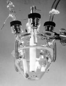
The cell for controlled-potential (bulk) electrolysis is usually a two-compartment (divided) cell, contained a carbon rod auxiliary anode and is separated from the cathode compartment by a coarse glass frit and methyl cellulose solvent electrolyte plug.[7] The reason for the two compartment cell is to separate cathodic and anodic reaction. The working electrode for bulk electrolysis could be a RVC disk, which has larger surface area to increase the rate of the reaction.[8]
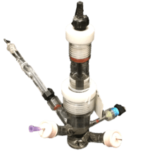
Controlled-potential electrolysis is normally utilized with cyclic voltammetry. Cyclic voltammetry is capable to analysis the electrochemical behavior of the analyte or the reaction. For instance, cyclic voltammetry could tell us the cathodic potential of an analyte. Since the cathodic potential of this analyte is obtained, controlled-potential electrolysis could hold this constant potential for the reaction to happen.[9][10]
Double Potential Step Chronoamperometry (DPSCA)
DPSCA is the technique whose working electrode is applied by the potential stepping forward for a certain period of time and backward for a period of time. The current is monitored and plotted with respect to time. This method starts with an induction period. In this period, several initial conditions will be applied to the electrochemical cell so that cell is able to equilibrate to those conditions.[11] The working electrode potential will be held at the initial potential under these conditions for a specified period (i.e. usually 3 seconds). When the induction period is over, the working cells switch to another potential for a certain amount of time. After the first step is completed, the working electrode's potential will stepped back, usually to the potential prior to the forward step.[12][13] The whole experiment ends with a relaxation period. Under this period, the default condition involves holding the working electrode potential of initial state for another approximate 1 seconds.[14][15] When the relaxation period is over, the post experiment idle conditions will be applied to the cell so that the instrument can return to the idle state1. After plotting the current as a function of time, a chronoamperogram will occur and it can also be used to generate Cottrell plots.[16]
Other two methods from Chronoanalysis
Chronopotentiometry
The application of Chronopotentiometry could be derived into two parts. As an analytical method, the range of analysis is normally in the range of 10−4 mol/L to 10−2 mol/L, and sometimes it will be as accurate as 10−5 mol/L. When the analysis is in the extremely lower range of concentration, lower current density could be used. Also, to get the accurate concentration determination, the transition time could be extended. In this area of analysis determination, chronopotentiometry is similar to polarography. Waves that are separable in polarography is also separable in chronopotentiometry.
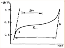
Chronopotentiometry is an effective method to study the mechanism of electrode mechanism. Different electrode will have different relationship between E and t in the chronopotentiometry graph. In this situation, E is the electrode potential in voltage and t is the reaction time in seconds. By the method of studying the relationship between E and t in the chronopotentiometry graph, we can get the information of a lot of mechanisms of electrode reactions, such as the electrode reaction of hydrogen peroxide and oxalic acid. The experiment of chronopotentiometry could be done in a very short time period, so it is a good method to study the adsorption behavior at the surface of electrode. By studying the chronopotentiometry graph of electrode after adsorption of iron ion, it is proved that the adsorption of platinum on iron ions exists. By studying the chronopotentiometry graph of platinum electrode adsorbing iodine, it is proved that the adsorption of iodine happening in the form of iodine molecules, not iodine atom.
Chronocoulometry
Chronocoulometry is an analytical method that has similar principle with chronoamperometry, but it monitors the relationship between charge and time instead of current and time. Chronocoulometry has the following differences with chronoamperometry: the signal increases over time instead of decreasing; the act of integration minimizes noise, resulting in a smooth hyperbolic response curve; and contributions from double-layer charging and absorbed species are easily observed.
See also
- Electroanalytical Methods
- Voltammetry
- Potentiometric titration
- Cottrell equation
- Jaroslav Heyrovský
References
- Kissinger, Peter; William R. Heineman (1996-01-23). Laboratory Techniques in Electroanalytical Chemistry, Second Edition, Revised and Expanded (2 ed.). CRC. ISBN 978-0-8247-9445-3.
- Bard, Allen J.; Larry R. Faulkner (2000-12-18). Electrochemical Methods: Fundamentals and Applications (2 ed.). Wiley. ISBN 978-0-471-04372-0.
- Zoski, Cynthia G. (2007-02-07). Handbook of Electrochemistry. Elsevier Science. ISBN 978-0-444-51958-0.
- J.M. Seveant, E. Vianello (1965). "Potential-sweep chronoamperometry: Kinetic currents for first-order chemical reaction parallel to electron-transfer process (catalytic currents)". Electrochimica Acta. 10 (9): 905–920. doi:10.1016/0013-4686(65)80003-2.
- "The Nobel Prize in Chemistry 1959".
- Peter James Lingane & Dennis G. Peters (1971) Chronopotentiometry, C R C Critical Reviews in Analytical Chemistry, 1:4, 587-634, DOI: 10.1080/1040834nu08542742
- Vanalabhpatana, Parichatr; Peters, Dennis (2005). "Catalytic Reduction of 1,6-Dihalohexanes by Nickel(I) Salen Electrogenerated at Glassy Carbon Cathodes in Dimethylformamide". J. Electrochem. Soc. 1152 (7): E222–E229. doi:10.1149/1.1928168.
- Cleary, James; Mubarak, Mohammad; Vieira, Kenneth; Anderson, Mark; Peters, Dennis (24 January 1986). "Electrochemical reduction of alkyl halides at vitreous carbon cathodes in dimethylformamide". Journal of Electroanalytical Chemistry and Interfacial Electrochemistry. 198 (1): 107–124. doi:10.1016/0022-0728(86)90030-6.
- Foley, Matthew P.; Du, Peng; Griffith, Kent J.; Karty, Jonathan A.; Mubarak, Mohammad S.; Raghavachari, Krishnan; Peters, Dennis G. (September 2010). "Electrochemistry of substituted salen complexes of nickel(II): Nickel(I)-catalyzed reduction of alkyl and acetylenic halides". Journal of Electroanalytical Chemistry. 647 (2): 194–203. doi:10.1016/j.jelechem.2010.06.001.
- Vieira, Kenneth L.; Peters, Dennis G. (December 1985). "Voltammetric behavior of tertiary butyl bromide at mercury electrodes in dimethylformamide". Journal of Electroanalytical Chemistry and Interfacial Electrochemistry. 196 (1): 93–104. doi:10.1016/0022-0728(85)85083-X.
- Faulkner, L. R.; Bard, A. J. Basic Potential Step Methods, Electrochemical Methods: Fundamentals and Applications, 2nd ed.; Wiley: New Jersey, 2000; 156-225.
- Cottrell, F. G. Z. Physik, Chem., 42, 1902, 385.
- Kambara, T. Bull. Chem. Soc. Jpn., 1954, 27, 523.
- Hyk, W; Nowicka, A.; Stojek, Z. Anal. Chem., 2002, 74, pp 149–157
- Long, J. W.; Terrill, R. H.; Williams, M. E.; Murray, R. W. Anal. Chem., 1997, 69, pp 5082–5086.
- Schwarz, W. M.; Shain, I. J. Phys. Chem., 1965, 69, pp 30-40.