Antenna equivalent radius
The equivalent radius of an antenna conductor is defined as:[1][2]
| Part of a series on |
| Antennas |
|---|
 |
|
Common types |
|
Safety and regulation
|
|
Radiation sources / regions
|
where denotes the conductor's circumference, is the length of the circumference, and are vectors locating points along the circumference, and and are differentials segments along it. The equivalent radius allows the use of analytical formulas or computational or experimental data derived for antennas constructed from small conductors with uniform, circular cross-sections to be applied in the analysis of antennas constructed from small conductors with uniform, non-circular cross-sections. Here "small" means the largest dimension of the cross-section is much less than the wavelength .
Formulas
The following table lists equivalent radii for various conductor cross-sections derived assuming 1) all dimensions are much less than , 2) for cross-sections composed of multiple conductors, the distances between conductors are much greater than any single conductor dimension. . Formulas for the square and triangular cross-sections follow from numerical evaluation of the double integral. All other formulas are exact.
| Cross-Section | Description | Equivalent Radius |
|---|---|---|
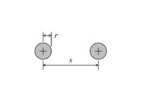 |
Two identical circular conductors | |
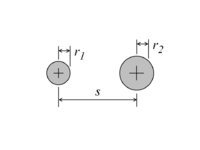 |
Two circular conductors with unequal radii |
|
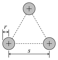 |
Identical circular conductors arranged in a triangle |
|
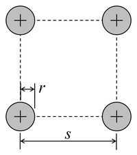 |
Identical circular conductors arranged in a square |
|
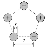 |
Identical circular conductors arranged in a pentagon |
|
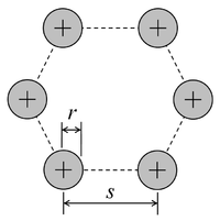 |
Identical circular conductors arranged in a hexagon |
|
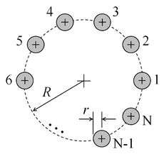 |
Identical circular conductors uniformly spaced around a circle |
|
 |
Flat, infinitely thin conductor | |
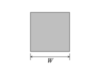 |
Square conductor | |
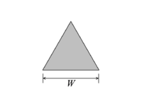 |
Equilateral triangle conductor |
Derivation
The equivalent radius is derived by equating the average magnetic vector potential at the surface of a conductor of arbitrary cross-section with the potential on the surface of a cylinder.
Assume a conductor's cross-section dimensions are small compared to the wavelength, current only flows axially along the conductor, the current distribution slowly varies along the conductor's length, and current is approximately uniformly distributed along its circumference (owing to the skin effect). Furthermore, only the current in a neighborhood around any point on the conductor significantly contributes to the potential at that point. Time dependence is ignored, as it may be incorporated by multiplying the current distribution by a time-varying sinusoid. These conditions imply that a quasi-static condition exists and that the geometry is, effectively, one of an infinitely long conductor with a constant surface current density (current per area), thereby reducing a three-dimensional problem to a two-dimensional one. Also implied is the magnetic vector potential is parallel to the conductor's axis.
First, consider the potential at a fixed point on the circumference of the arbitrary cross-section. With the circumference divided into differential segments , the current distribution may be approximated by placing a vertical line current within each segment, each with a linear density of (current per length). It is well known that the potential of such a line current is , where is the permeability constant. The potential at is the sum of the potentials for all the strips, which is
The average potential is then
Now consider the case of cylinder with the same linear current density as the conductor of arbitrary cross-section. It is also well known that the potential at any point on its surface, which is also equal its average potential, is
Equating and yields
Exponentiation of both side leads to the formula for the equivalent radius.
The formula for the equivalent radius provides consistent results. If the conductor cross-section dimensions are scaled by a factor , the equivalent radius is scaled by . Also, the equivalent radius of a cylindrical conductor is equal to the radius of the conductor.
References
- E.A. Wolff, Antenna Analysis, Chapter 3, John Wiley & Sons, New York, NY, Second Edition, 1966.
- David M. Drumheller K3WQ, The Antenna Equivalent Radius: A Model for Non-Circular Conductors, QEX, American Radio Relay League, Newington CT, 2017 March/April pp. 10ff.