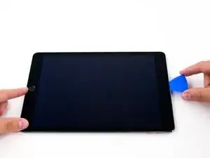
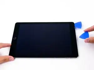
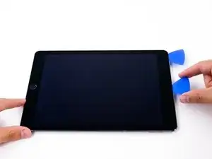
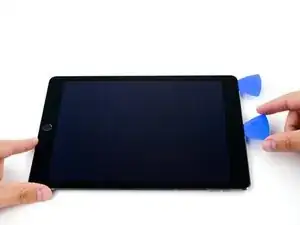
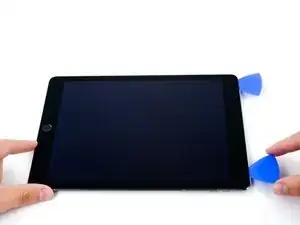
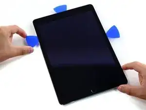
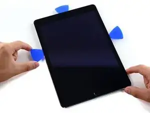
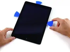
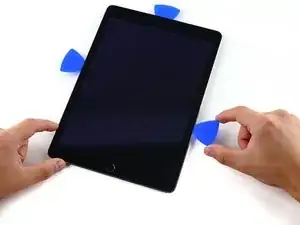
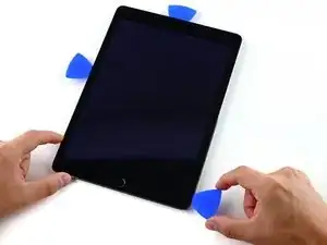
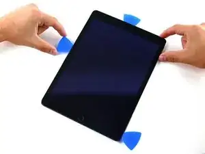
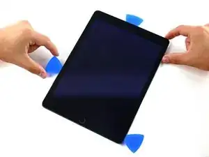
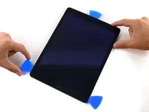
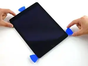
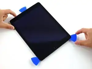
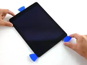
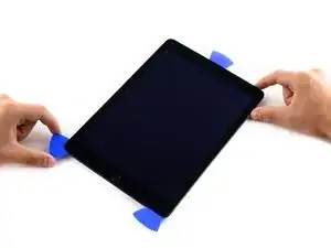
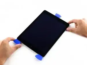
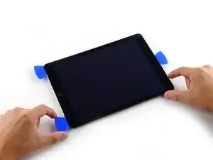
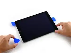
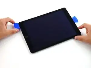
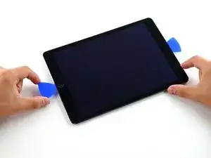
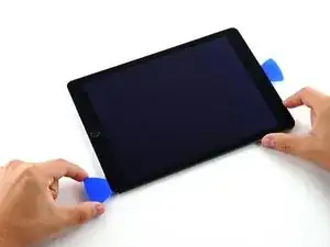
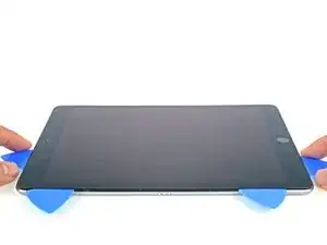
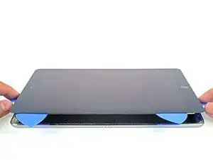
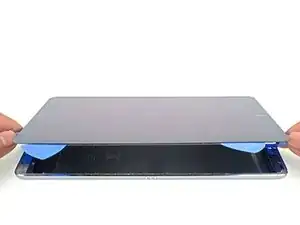
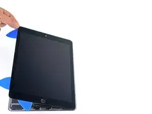
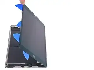
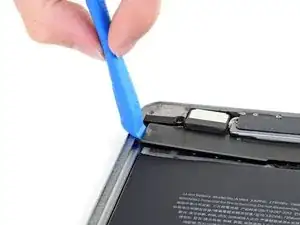
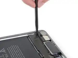
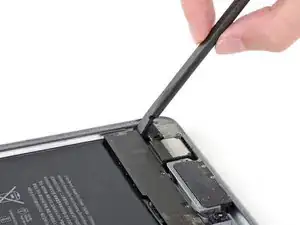
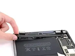
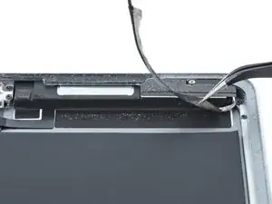
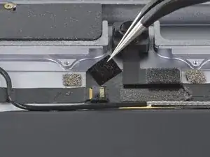
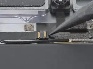
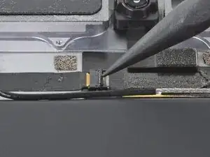
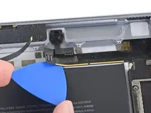
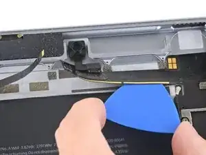
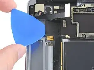
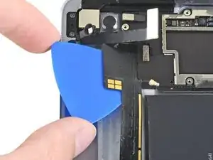
Introduction

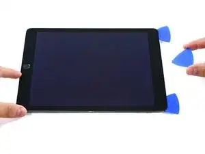
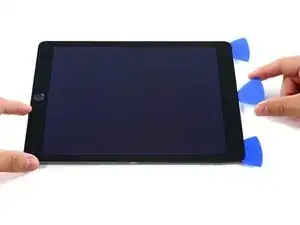
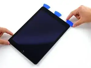
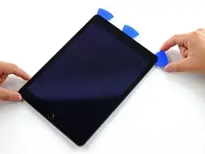
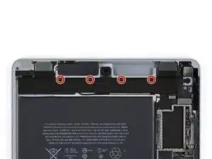
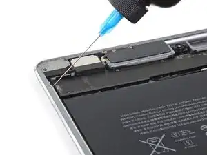
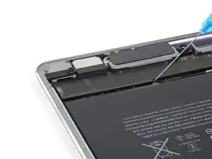
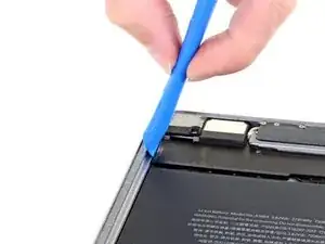
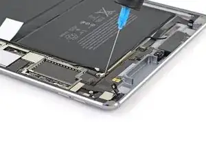
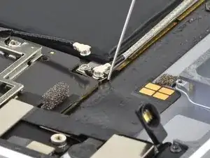
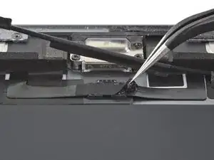
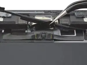
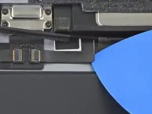
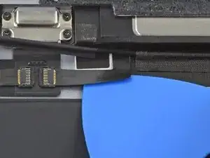
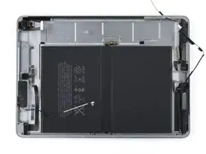
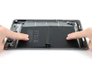
Follow this guide to remove and replace the battery for the iPad Pro 9.7”.

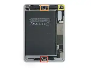
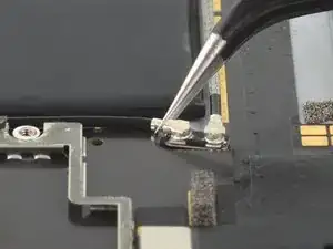
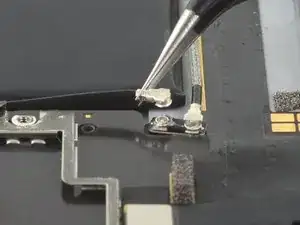
This extensive procedure requires you to remove the logic board in order to free the battery for removal.

This guide is written with a cellular model iPad Pro. If your iPad is not the cellular model, skip the first step.

Because there are steps in this guide where the battery may remain connected to the logic board, leave the iPad on until the battery is completely discharged (the iPad turns itself off) before attempting this guide.

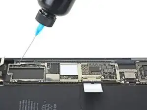
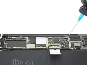
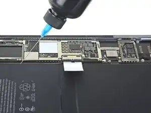
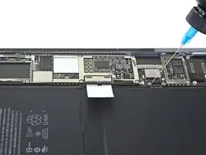
Have plenty of high concentration (over 90%) isopropyl alcohol to help make residue cleanup easier.

If your battery is swollen, take appropriate precautions.

  1. UxQvGDUdB2aClPpM
    UxQvGDUdB2aClPpM
    1bKjyNArvPJp63Sk
    gvfXTQeknUsk4HI1
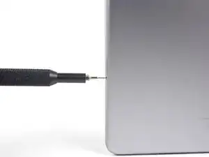
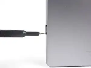
    • Insert a SIM card eject tool, bit, or a paperclip into the small hole in the SIM card tray, located near the bottom edge of the iPad.

    • Press firmly to eject the tray.

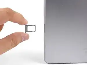
    • Remove the SIM tray.

    My iPad Pro 9.7 wifi only has no pinhole for sim card

    Michelle -

    You’re right! The Wi-Fi only model does not have a pinhole. Skip this step for your iPad.

    Arthur Shi -

  2. 4fSrpT12RPOorLqZ
    4fSrpT12RPOorLqZ
    YEXM13x4vxQLEIqa
    CUUZal13vZyLAeHH
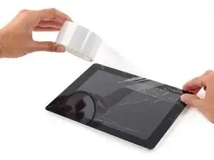
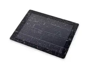
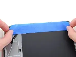
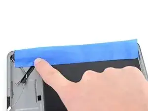
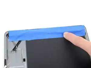
    • If your display glass is cracked, keep further breakage contained and prevent bodily harm during your repair by taping the glass.

    • Lay overlapping strips of clear packing tape over the iPad's display until the whole face is covered.

    • This will keep glass shards contained and provide structural integrity when prying and lifting the display.

    • Do your best to follow the rest of the guide as described. However, once the glass is broken, it will likely continue to crack as you work, and you may need to use a metal prying tool to scoop the glass out.

    • Wear safety glasses to protect your eyes, and be careful not to damage the LCD screen.

    Covering the screen with tape proved an essential safety step with the ipad display/lcd I just replaced. The screen was so badly broken that a part of it was almost powder, but the combination of the tape and sticky adhesive residue kept most of that together, and cleanup was pretty easy as a result. One caveat, though, is that the tape will probably make the suction cup useless for pulling up on the display. It did for me, anyway.

    John Lasseter -

  3. r4amr5F6MjBUIQnt
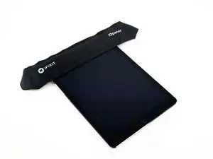
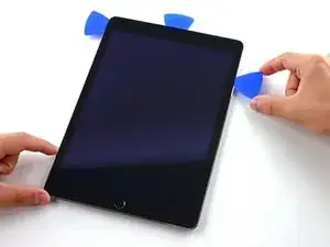
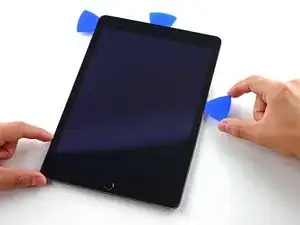
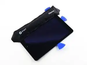
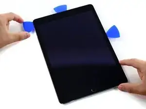
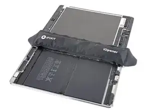
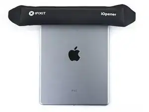
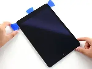
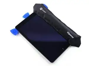
    • The following steps involve using an iOpener to soften the adhesive holding the front panel assembly in place. When using the iOpener, be sure to heat it in the microwave for no more than 30 seconds.

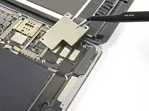
    • Handling it by the tabs on either end, place a heated iOpener over the top edge of the iPad.

    • Let the iOpener sit on the iPad for two minutes to soften the adhesive securing the front panel to the rest of the iPad.

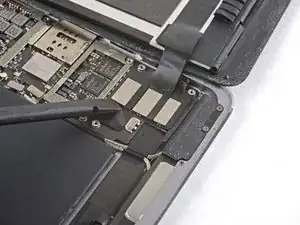
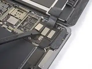
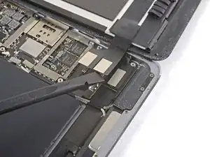
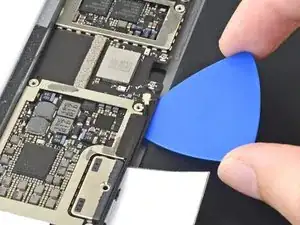
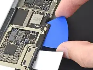
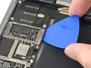
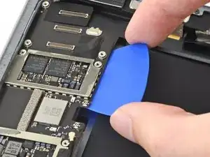
    I see a lot of videos that show using a heat gun on low to soften the adhesive. I know there is inherent risk with this since you could start delaminating things, but is it something that could be considered (at your own risk)? Or is it something that could have more risks than I am realizing?

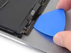
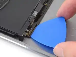
    joshcorey -

    Yes, you can definitely use a hair dryer, heat gun, or a heating pad. If you're using a heat gun, be careful not to overheat the display. The surface should feel slightly too hot to the touch.

    Arthur Shi -

  4. vbug1VOBMObXrrNJ
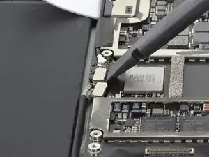
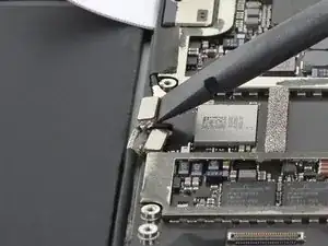
    vbug1VOBMObXrrNJ
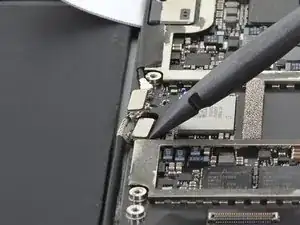
    lM2svovREMXARVPx
    QQCvcb1RJlUkbUQW
    • While the iPad looks uniform from the outside, there are delicate components under certain portions of the front glass. To avoid damage, only heat and pry in the areas described in each step.

    • As you follow the directions, take special care to avoid prying in the following areas:

    • Home Button

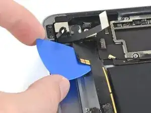
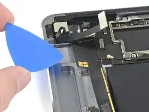
    • Front Facing Camera

    • Main Camera

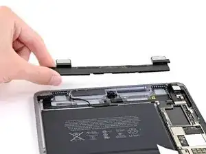
    Verwirrend: Es sollte heissen, dass man an den beschriebenen Stellen eben NICHT hebeln sollte.

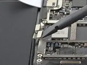
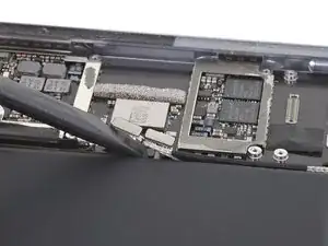
    Felix -

    Danke! Ich habe den Teil mit dem NICHT hebeln nochmal hervorgehoben.

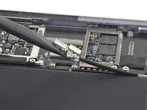
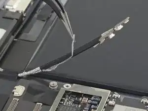
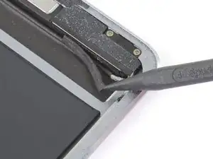
    Fabian Neidhardt -

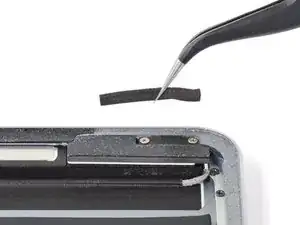
    The screen cable is on the right side at the bottom. Be super careful not to slice too deeply there

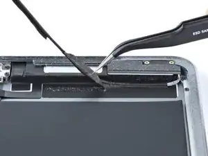
    Gerald -

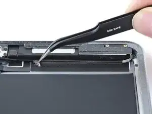
  5. KNVk2a1AUMciEshg
    KNVk2a1AUMciEshg
    cFIoQKTkU2nO5tfW
    ciSmehC6fBvHFjKR
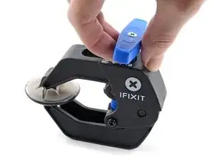
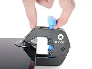
    • The next two steps demonstrate the Anti-Clamp, a tool we designed to make the opening procedure easier. If you aren't using the Anti-Clamp, skip down two steps for an alternate method.

    • For complete instructions on how to use the Anti-Clamp, check out this guide.

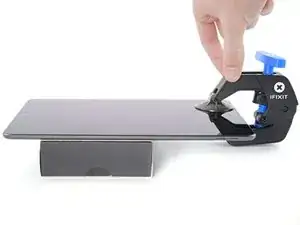
    • Elevate the iPad enough for the Anti-Clamp's arms to rest above and below the screen.

    • Pull the blue handle towards the hinge to disengage opening mode.

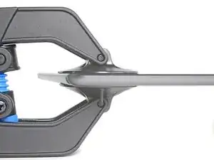
    • Position the suction cups near the top edge of the iPad—one on the front, and one on the back.

    • Push down on the cups to apply suction to the desired area.

    • If you find that the surface of your device is too slippery for the Anti-Clamp to hold onto, you can use packing tape to create a grippier surface.

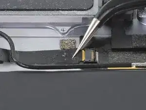
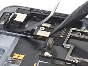
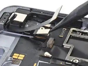
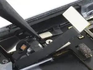
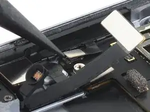
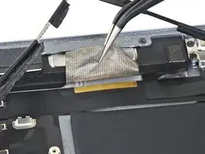
  6. f1wKrgiJGt1qr2KD
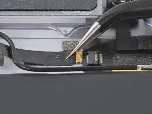
    f1wKrgiJGt1qr2KD
    duPJTFGfLCfRIlTF
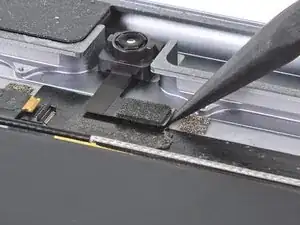
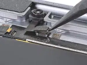
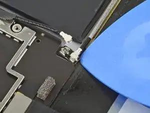
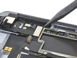
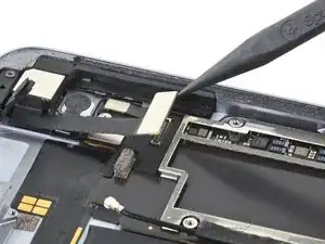
    jItC1msuNMKW5yOH
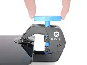
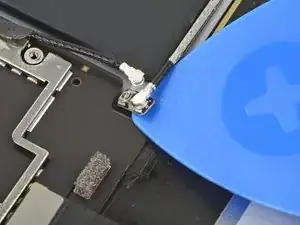
    • Push the blue handle away from the hinge to engage opening mode.

    • Turn the handle clockwise until you see the cups start to stretch.

    • Make sure the suction cups remain aligned to each other. If they begin to slip out of alignment, loosen the suction cups slightly and realign the arms.

    • Wait one minute to give the adhesive a chance to release and present an opening gap.

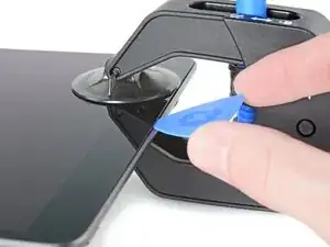
    • Insert an opening pick under the screen when the Anti-Clamp creates a large enough gap.

    • If the Anti-Clamp doesn't create a sufficient gap, apply more heat to the area and rotate the handle clockwise half a turn.

    • Don't crank more than a half a turn at a time, and wait one minute between turns. Let the Anti-Clamp and time do the work for you.

    • Skip the next two steps.

    Do not use the anti clamp beyond this step. Doing so will run the risk of putting pressure on the screen and cracking it. Only use it for the initial opening of the device.

    Playincrzy -

  7. rpaBWg5X1LUnivHt
    rpaBWg5X1LUnivHt
    NXKEJYkJ5HpXf5cV
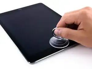
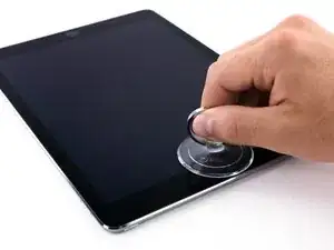
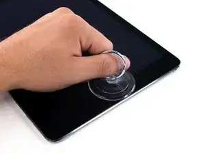
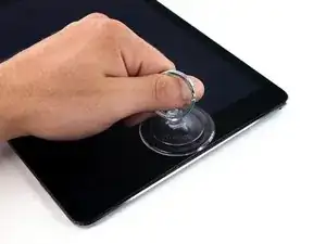
    • Place a suction cup over the iPad's front-facing camera and press down to create a seal.

    • To get the most leverage, place the suction cup as close to the edge as possible without going past the edge of the display.

  8. mJCqfjEDtJeihiXC
    mJCqfjEDtJeihiXC
    LhCLCjtgwcD4eQVo
    nZkUghUs1xfKEWTf
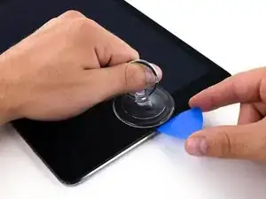
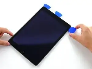
    • Firmly pull up on the suction cup to create a small gap between the front panel and the rear case.

    • Do not pull too hard or you may shatter the glass.

    • Once you've opened a sufficient gap, insert an opening pick into the gap to prevent the adhesive from resealing.

  9. UBZTHwdRqbwRLJAl
    UBZTHwdRqbwRLJAl
    RTJrYjnQCiMxQGEw
    4TraNDygnvQCXDJV
    • Slide the pick along the edge of the display, towards the headphone jack.

    • If there is still a considerable amount of resistance when sliding the opening pick, repeat the iOpener heating procedure and apply additional heat.

    • Don't insert the pick past the bezel into the display area, or you will damage it.

    • A good rule of thumb is to never insert the opening pick more than a quarter inch into the iPad.

  10. y34OmvNZddjUsgJf
    y34OmvNZddjUsgJf
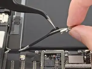
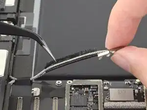
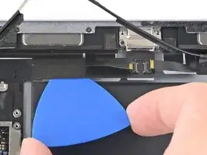
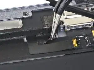
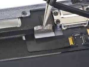
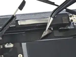
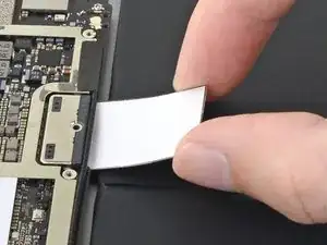
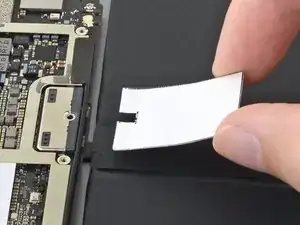
    dKyTUwZlqudvsrwS
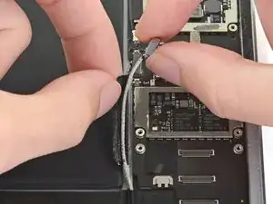
    • Insert a second opening pick by the front-facing camera.

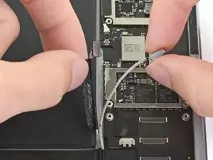
  11. VlouIlKDBobp21ht
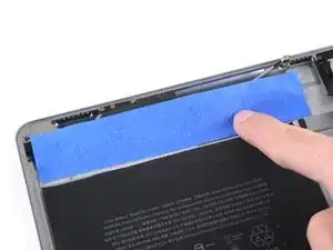
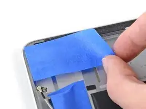
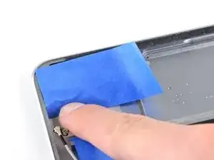
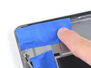
    VlouIlKDBobp21ht
    4D3HnAB5lW6NWtQP
    usBnHAdBOnUhgKgZ
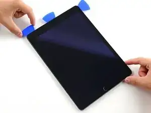
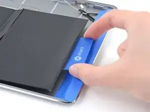
    • Slide the second pick along the top edge of the iPad, towards the Sleep/Wake Button.

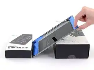
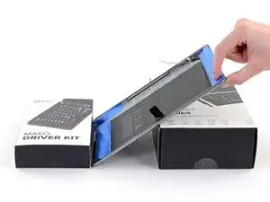
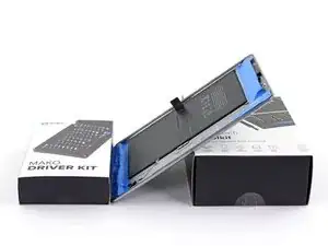
  12. QItKpaRbXb1UvjCF
    QItKpaRbXb1UvjCF
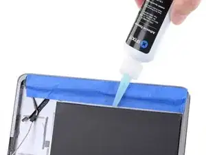
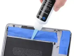
    GWdnFUu2a2WqNBRk
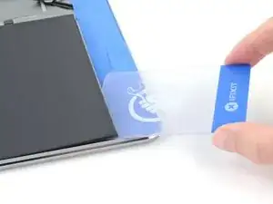
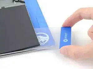
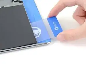
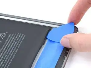
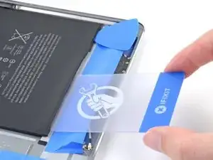
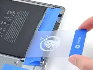
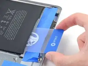
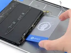
    • Insert a third pick by the front-facing camera.

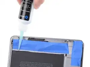
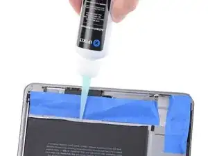
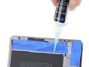
  13. SB6QxHsLajVvHKLF
    SB6QxHsLajVvHKLF
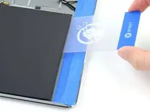
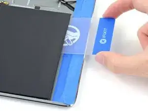
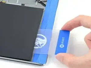
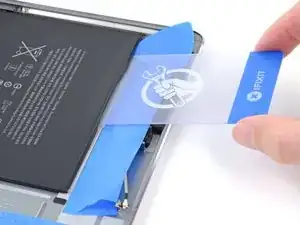
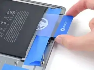
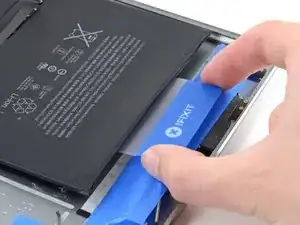
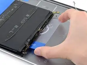
    6jAjQvNWJtPA1icQ
    bfWiL6JjqPuCHktD
    • Bring the right opening pick down and around the top right corner of the iPad.

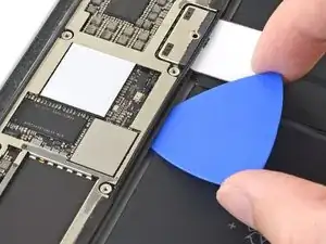
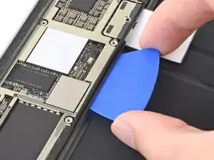
  14. iEwCprM5hUbjMa5M
    iEwCprM5hUbjMa5M
    btBkuNsD1BGWdmNi
    ZeLYciNptnjMD5sN
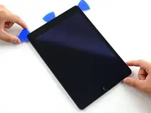
    • Bring the left opening pick around the top left corner of the tablet.

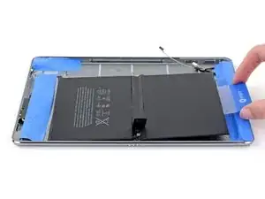
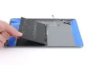
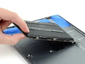
  15. fpXSlsGA4PuXZwtC
    • Reheat the iOpener and lay it over the right edge of the display to loosen the adhesive underneath.

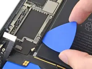
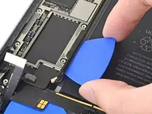
  16. bYJQLgFB46cU2pVJ
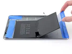
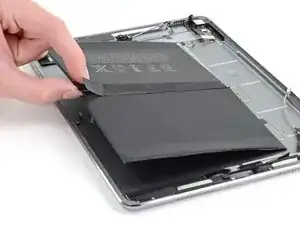
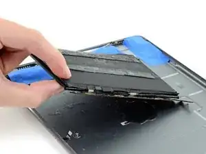
    bYJQLgFB46cU2pVJ
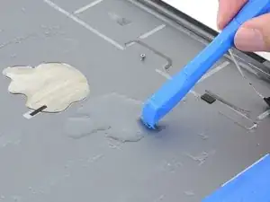
    bZDFr4X45b4DahBn
    s1wTnCHfVesRTpQu
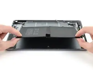
    • Slide the right opening pick roughly halfway down the display.

  17. JMuZWuybr3UclCyZ
    • Reheat the iOpener and apply heat to the left side of the iPad.

  18. IQRxoNTBSGtLM3i2
    IQRxoNTBSGtLM3i2
    ETnV2UuToukcU3om
    jJatPsp4QkC3AahX
    • Slide the left-hand opening pick about halfway down the edge of the display.

  19. GReHqx2PqZURrOmS
    GReHqx2PqZURrOmS
    EKxY1RGlSXtPGpwj
    QoZPMgkyQQwPXR6j
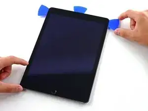
    • Slide the opposite opening pick down to the bottom right corner of the iPad.

    • If necessary, reheat the adhesive on the right edge to loosen the display assembly.

    The screen cable is on the right side at the bottom. Be super careful not to slice too deeply there

    Gerald -

  20. wwPbdKhkSwI5hQMG
    wwPbdKhkSwI5hQMG
    LaZr2wpWCByppuVW
    UIXuRBEr3LiC3Bhm
    • Slide the left-hand opening pick down the edge of the display until you reach the corner.

    The screen cable is on the right side at the bottom. Be super careful not to slice too deeply there

    Gerald -

  21. UsPELiDHRgD5GTqy
    • Use the iOpener to apply heat to the bottom edge of the iPad.

  22. wygPNSUXUUeMhjok
    wygPNSUXUUeMhjok
    YmJCAGY5oke2TUDU
    IlKVDslEYyMPKjBL
    • Bring the right-hand opening pick around the bottom corner of the iPad.

  23. xfVKIvrVyEGfeDkD
    xfVKIvrVyEGfeDkD
    3RsbTJPXwtVsrU5J
    2yL1bOTG6QjYfuw1
    • Repeat for the left-hand pick.

    • Reheat and reapply the iOpener as needed.

  24. IUNdFVqTQHS6UKiG
    IUNdFVqTQHS6UKiG
    h1UtPwFlqFxDEvCB
    • Remove the right-hand opening pick at the bottom of the iPad.

  25. XSUmMZChFquPbMVK
    XSUmMZChFquPbMVK
    BRuNiWvEDx3xpiaU
    G4mFOROitEkXfpcQ
    • Slide the left-hand opening pick along the bottom edge of the display, then remove it from the bottom right corner of the iPad.

    • Be very careful to not insert the pick more than a quarter inch into the display to avoid damaging the Home Button and display cables underneath.

  26. UMABNUvs1JAY5CnQ
    UMABNUvs1JAY5CnQ
    pjKHFWXeNHKb1Fwn
    n5dLBWCNCLviV3tO
    • Use picks to ensure most of the adhesive has been cut through on the top, left, and bottom sides.

    • Twist the top and bottom picks to separate the display assembly from the rear case.

    • Do not attempt to remove the display—it is still attached to the rear case.

  27. EUHYHMoMYHmZQtDe
    EUHYHMoMYHmZQtDe
    3Jrxx2QT1hOKvYfK
    QPswhfhlMOBus4Xt
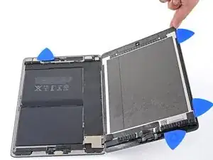
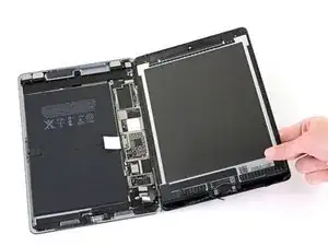
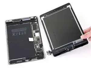
    • Swing the display assembly towards the right of the case, using the right edge as a hinge.

    • As you move the display assembly, make sure that the display ribbon cable is not being stressed.

    • Continue swinging the display assembly until it lays flat next to the rear case.

  28. OmKcSXAUbgvGwQDa
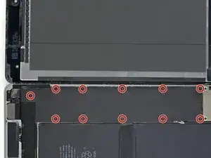
    • Use a Phillips screwdriver to remove the eleven 1.3 mm screws securing the EMI shield.

  29. pmOYYDEugngE3r5u
    • Apply a heated iOpener to the EMI shield on the logic board for one minute.

  30. e1sL5f4ExNuJAext
    e1sL5f4ExNuJAext
    QiJq5COIviJNFLjS
    2IYWhakABvD1ZxOE
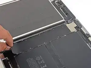
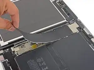
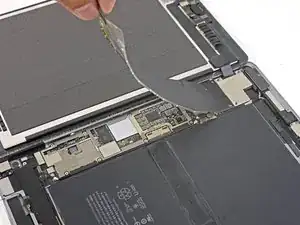
    • Lift the logic board EMI shield, starting at the edge nearest the top of the iPad.

    • Slowly peel the EMI shield up from the logic board.

    • This takes a bit of force due to the many tiny clips securing the shield, and the shield may deform slightly. That's okay—try to keep the deformation to a minimum, and it will lay flat when reinstalled and screwed down.

    • Remove the logic board EMI shield.

    Don't peel the cover as shown from a short side. Lift the long side to avoid creasing the cover so much. This way it will lie flat when you reassemble it and not look so ugly. Also, you won't have to straighten so many creases with pliers

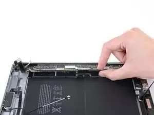
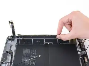
    Jim Meyers -

  31. D6aqtQGXLmCYbHBt
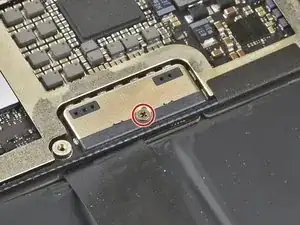
    • Use a Phillips driver to remove the 1.7 mm-long screw securing the battery connector.

    What size is this screw?

    Austin Martin -

    i get 1.65mm with my calipers but the 1.3s read 1.25 on my calipers too, so probably a 1.7mm

    bunjamins -

  32. yQVBO6oOKlNeidgA
    yQVBO6oOKlNeidgA
    WNbapGR1pFsKRftp
    pg232afeScFRxNik
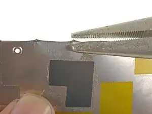
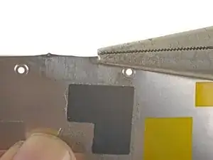
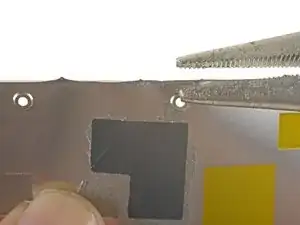
    • If the EMI shield has any sharp protrusions after removal, you should flatten them before reinstalling the shield.

    • Squeeze the sharp protrusion with a pair of pliers to flatten it.

    • Repeat the process for all sharp protrusions along the edges of the EMI shield.

    Don't peel the cover as shown from a short side. Lift the long side to avoid creasing the cover so much. This way it will lie flat when you reassemble it and not look so ugly.

    Jim Meyers -

  33. XpIgLlSVJMdt4NyP
    XpIgLlSVJMdt4NyP
    V1V2DyoEgl4mTn6v
    yL3XcWjTZ5XaXsLf
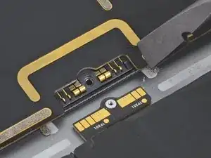
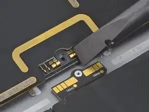
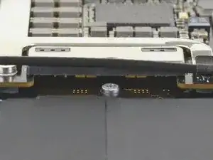
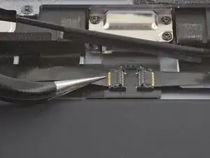
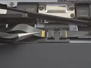
    • These photos show what the battery connector looks like underneath the logic board. Use these photos as a reference while you safely disconnect the battery.

    • Notice that the battery connector has cantilever springs on the logic board that press against the battery contact pads. Since both the logic board and battery are glued down, you'll need to slide something thin and flexible between the contact points to disconnect the battery.

    Le connecteur de batterie est il réparable si abîmé ?

    Maverick -

  34. ydsWDNC5XgN5TGkA
    ydsWDNC5XgN5TGkA
    lYxVPnwP1yejWAfd
    QgNCDMbA2bNqcQio
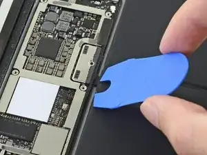
    • Be careful when you isolate the battery using a battery blocker. The battery contacts are easily bent or broken, resulting in irreversible damage.

    • Ensure that the iFixit logo on the battery blocker is facing up.

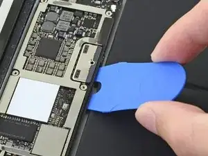
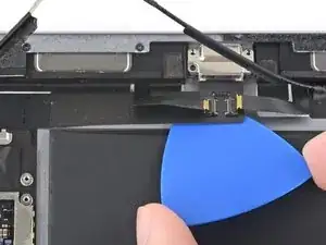
    • Slide the battery blocker underneath the left side of the logic board's battery connector at a 35 degree angle.

    • The battery blocker's right prong should slide between the left side of the logic board's battery connector and the battery's contact pads. The left prong should slide under the logic board.

    • Don't push the battery blocker underneath the connector or logic board with excessive force. If you're having trouble fitting the battery blocker underneath the logic board, refer to the next step for information on loosening the logic board. You can also try using a playing card to disconnect the battery instead.

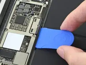
    • The battery blocker or playing card should slide under the logic board without encountering any blockages. After insertion, they should rest at a 15 degree angle.

    • Leave the battery blocker in place as you work.

    le connecteur de la batterie est t’il remplaçable ou repérable si jamais abîmé ?

    Maverick -

  35. GNruVZHL1TYb2igd
    GNruVZHL1TYb2igd
    xlWNIlPRyuIaf3DP
    • If the battery blocker doesn't easily slide under the logic board, follow these steps to partially loosen the logic board from the frame:

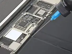
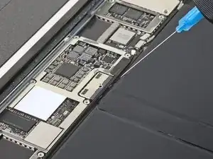
    • Apply a few drops of high-concentration (90% or higher) isopropyl alcohol under the logic board to the left and right of the battery connection.

    • Wait one minute for the isopropyl alcohol to weaken the adhesive under the logic board.

    • Try to insert the battery blocker. If the logic board doesn't easily lift up, apply a few more drops of isopropyl alcohol.

    • This doesn't apply when using the playing card method to disconnect the battery because the playing card is only inserted between the battery connector and the battery contact pads.

  36. SSnJJGWG4QmSor5T
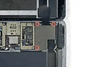
    • Use a Phillips screwdriver to remove the three 1.3 mm Phillips screws securing the display cable bracket.

    i think we need to talk about the battery situation here. apple change up the style of battery connector on this model as well as some others. if someone can add to this list and add the appropriate photos in the right spot should help someone else. the battery tabs are open towards the battery side and inserting a tool in this area can pry them open further and damage or rip off the tab. some have found that by lifting on either side of the battery tab, they would not even encounter the tabs.

    greg -

  37. 1a4ywPCBXTXe1uPJ
    1a4ywPCBXTXe1uPJ
    NQOaPfW4OXpa5vek
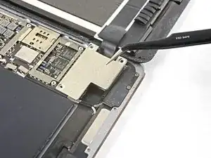
    • Remove the display cable bracket.

    A tab was folded over a connector of some sort on the bottom side. I found it was a better to pull from the top to the bottom to fold the tabs slightly to remove this cover.

    rosecitymech -

    Actually it helps to move the cover slightly towards the bottom of the iPad as that disengages to tabs…

    DeeAnn Hopings -

  38. N3WqLqmlprqjmhha
    N3WqLqmlprqjmhha
    vyNRHkW1HFHRt5rb
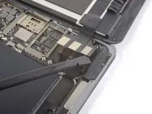
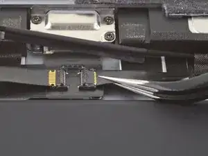
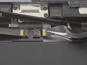
    • Use the flat end of the spudger to disconnect the display assembly connector from the motherboard socket.

  39. 6ym1twSljAhoSG46
    6ym1twSljAhoSG46
    FMHLJUerOdlvCIJh
    • Repeat the previous step for the two remaining connectors.

  40. VfYWrFtvNprHjYIC
    VfYWrFtvNprHjYIC
    C5LVpSEBGFwHVbQb

    You "CAN" skip steps 41 through 98 and 102-109 if you're confident in your repair abilities and PATIENT. Lots of alcohol around all the edges of the battery, and apply heat to the back cover on one half of the battery, the slowly ease your "card under the edges of the battery. Wiggle it back and forth and add more alcohol under the edges of the battery where your working; DONT PUSH your card to hard or you will sli[p and damage components. Then do the same for the other half. When both halves are loose, fold over one end and slide the flat edge off the spudger under the area of the logic board next to the battery connector, then do the same to the other side; you want just enough of a gap under the logic board to lift the battery tab off of the post then you can remove the battery.

    Gregg Stanley -

    ディスプレイアッセンブリを外して、黒くて古い接着テープをはがしすためにぴっぱったら、ディスプレイと本体基盤を接続するコネクターのテーブを不注意で切断してしまった。これで、交換はあきらめで中止。注意されたし。ちなみに、手順41~89は省いてもバッテリー交換ができるのではないかと思います。

    susuper -

  41. IYUFLXxOeLlihujU
    IYUFLXxOeLlihujU
    MJUUPnyjP6NRxmub
    wBLG3cpWIXHSr5yh
    • Slide an opening pick under the right ambient light sensor to loosen its adhesive.

    • There are two pegs on the shelf that position the ambient light sensor—one on the bottom edge and one near the top edge.

    The "right ambient light sensor" can be replaced?

    If yes, where can I find the replacement part?

    Michael Rodriguez -

    The light sensor has a rubber collar. If you lift the cover you can see a tiny peg pushed upwards onto the bottom of the sensor base. It’s the base you need to lift and it is stuck down

    Gerald -

  42. 5HkHHPpUTEjqcUCE
    • Use a Phillips screwdriver to remove the four 1.9 mm-long screws securing the upper speaker to the frame.

  43. Cm14Q1sUYtyQpVMC
    Cm14Q1sUYtyQpVMC
    nBjRvDVtvBU2KnI3
    • Strong adhesive secures the upper speaker to the frame.

    • Apply a few drops of high-concentration (90% or higher) isopropyl alcohol under the upper speaker.

    • Wait one minute for the isopropyl alcohol to weaken the adhesive under the upper speaker.

  44. pMBIkLrgnjqVAWAl
    pMBIkLrgnjqVAWAl
    QvQ16GyiAXRDAPBY
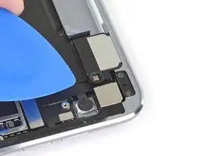
    • Use an opening tool to pry up the left edge of the upper speaker.

    • Try to avoid bending the upper speaker while prying it up. Some bending will likely happen during this process, but excessive bending may damage the upper speaker.

    • If the upper speaker isn't detaching from the frame, apply a few more drops of isopropyl alcohol.

    These next 3 steps are the most difficult of the whole process. The speaker is glued down along its whole length which must all be freed. Use the iopener underneath the top of the iPad whilst you are waiting for the alcohol to work to help soften the glue.

    On the left hand side, there is a flat cable glued to the back plate and the speaker is then glued on top of the cable. So when you put the alcohol down it’s most likely to deboned the cable which will remain attached to the speaker as you lever it up and need carefully separating somehow.

    There is a zif connector on that cable underneath the speaker and just to the left of the front facing camera so there’s not much play. If you are unable to remove cable from the bottom of the speaker, you’ll pull the cable out of the connector as you lift the speaker. Don’t lever the speaker downwards (next step) until this zif connector is detached or you’re trash the connector itself.

    There’s also a round wire which passes underneath the speaker, that’s a bit stronger.

    Gerald -

  45. uHMlbQnjXYxWDGyL
    uHMlbQnjXYxWDGyL
    46DsylclyRAAdRyj
    • Use the flat end of a spudger to push the left side of the upper speaker toward the battery just enough for the left speaker to slide out of its recess in the frame.

    The external speaker (headphone socket) on the left side of the speaker must be removed. 2 screws for the cover, 1 for the socket support. As well as a sensor of some sort. The cover for the sensor came off separately.

    Rogie B -

    I didn’t remove that speaker but doing so may give to more access to lift the speaker unit upwards.

    DO NOT move the speaker downwards until you have completely separated the speaker from the flat cable glued to the bottom of it on the left hand side or disconnected the zif connector. See my comment in previous step.

    Gerald -

  46. YSR3WaZTCiSvcSlA
    YSR3WaZTCiSvcSlA
    i2TYt2QoPvPZVL6Y
    • Lift and remove the upper speaker from the frame.

    • There are multiple cables under the upper speaker. Be careful not to damage them while removing it.

    • If any cables are still attached to the upper speaker while you lift it up, carefully peel them off of the upper speaker. You can apply more isopropyl alcohol if they don't easily peel away.

    • If the ZIF connector sticker near the front camera comes off while removing the upper speaker, reapply it to the ZIF connector.

    • If the ZIF connector near the front camera disconnects while removing the upper speaker, use the pointed end of a spudger to flip up the locking flap. Then, reinsert the ribbon cable and close the locking flap.

    • During reassembly, make sure the right ambient light sensor is on top of its shelf.

    • If there's any alcohol solution remaining in the device, carefully wipe it off or allow it to air dry before reinstalling the upper speaker.

    You are going to disconnect the zif connector later. If it’s popped out there’s not need to put it back.

    Gerald -

  47. d1RZJlFU2CIZr4Hq
    d1RZJlFU2CIZr4Hq
    iCulgDXlAdAXgDeq
    • Use the flat end of a spudger to disconnect the right antenna's coaxial connector from its socket.

    • To reinstall, hold the connector in place and gently press straight down. The connector will “snap” into its socket.

  48. 6BSXyup2iXhyPWWH
    6BSXyup2iXhyPWWH
    B6LYMXieTVAXDPMY
    • Use the flat end of a spudger to disconnect the left antenna's coaxial connector from its socket.

    • To reinstall, hold the connector in place and gently press straight down. The connector will “snap” into its socket.

  49. YLXWISg3dtNPoXII
    YLXWISg3dtNPoXII
    jukpIAibXcrZQLAv
    • Use the flat end of a spudger to lift the bundled left and right antenna cables away from the frame.

    • Be careful not to puncture the battery with the spudger.

    • The sticker bundling the antenna cables together is lightly adhered to the frame.

  50. kRNIv6lJZZqXpfb1
    • Use a pair of tweezers to remove the adhesive that was securing the bundled antenna cables to the frame.

    • Take care not to damage the antenna cables with the sharp tips on the tweezers.

    • During reassembly, apply pre-cut adhesive to the bundled antenna cables to secure them to the frame.

  51. xagxeCMtFXeEl2TC
    xagxeCMtFXeEl2TC
    djlFKRKZVX3TkGIg
    • Use a pair of tweezers to peel up the sticker bundling the left and right antenna cables together.

  52. tEQcXTBjPICIXAxg
    tEQcXTBjPICIXAxg
    RJT2f6WIEkX5VvyF
    • Peel the right antenna cable off of the sticker.

  53. 2Kfc6TxTsDx1dJ54
    2Kfc6TxTsDx1dJ54
    UavUsjVpXYhhFJhv
    • Use a pair of tweezers to lift up the small sticker near the lower right speaker securing the right antenna to the frame.

  54. jkEaMnFO3DYWoJrO
    jkEaMnFO3DYWoJrO
    nFDxXCdk6bGOcoxi
    PNLsogwCbaeRp3fw
    • Use the pointed end of a spudger to detach the foam spacer adhered to the second right antenna sticker.

  55. 2jyDlBRndyVxQrDI
    • Remove the foam spacer from the second right antenna sticker.

  56. aSEVboi4sEKvFFoo
    aSEVboi4sEKvFFoo
    rdvPgT2T3IrfInns
    • Use a pair of tweezers to detach the large right antenna sticker between the logic board and the antenna.

  57. wNPKjTV2WpaBhJHi
    wNPKjTV2WpaBhJHi
    21FDrPVljICYTVRJ
    • Use a pair of tweezers to lift up the small sticker next to the lower right speaker securing the left antenna cable to the frame.

  58. 36ESNvr6awYpc3VM
    36ESNvr6awYpc3VM
    dWwggl1YDONCetx3
    • Use a pair of tweezers to detach the large left antenna cable sticker near the lower right speaker.

  59. KonVYukK3XLYYvM3
    KonVYukK3XLYYvM3
    Mb6Sm5YqbQEvVN1T
    • Use a pair of tweezers to lift the left antenna and its third sticker away from the Lightning port area of the frame.

  60. XrGMQSfTIuwEdLpB
    XrGMQSfTIuwEdLpB
    GoNxgQrjZfpvNYPX
    qvuki5KOuJWATeAa
    • Use the pointed end of a spudger to detach the foam spacer adhered to the fourth left antenna cable sticker.

  61. dYgmVA2IjP4NR1VE
    • Remove the foam spacer from the fourth left antenna cable sticker.

  62. CuWRpltlptxmSZB4
    CuWRpltlptxmSZB4
    MSJrnwqiNhLUhrIg
    hjwOsI3helJhKepm
    • Use a pair of tweezers to lift up the fourth left antenna cable sticker.

  63. ATkwJIyTbg1Nw5Wv
    • Use a pair of tweezers to remove the sticker covering the left ambient light sensor's ZIF connector.

    Der ZIF Stecker liegt versteckt unter der GSM/LTE Antenne.

    Bernd Löhr -

  64. Menif1QZZMYYlHlo
    Menif1QZZMYYlHlo
    tSrUdowcAQTEBDtf
    • Use the pointed end of a spudger to flip up the locking flap on the left ambient light sensor's ZIF connector.

  65. 5Bi2HQxiAhSVikA2
    5Bi2HQxiAhSVikA2
    JqTM3Kwo3YW1a4Iv
    • Use a pair of tweezers to grip the left ambient light sensor ribbon cable as close as possible to its contacts.

    • Pull the ribbon cable out of the ZIF connector.

  66. qhOIGV5X1Ta14UMa
    qhOIGV5X1Ta14UMa
    WM2X1eLdXWOIvGdg
    • Use the pointed end of a spudger to disconnect the front camera's press connector from its socket.

    • Be careful to pry only under the edge of the connector, and not under the socket itself. If you pry under the socket, you will separate it from the circuit board.

    • To reconnect, align the connector carefully over its socket and press down with your fingertip—first at one side, then the other—until it clicks into place.

    • Do not press down on the middle until the connector is fully seated—if it's misaligned, the connector can bend, causing permanent damage.

  67. ZPcoPOKAcL6IqYmf
    ZPcoPOKAcL6IqYmf
    B3XCNqjFSrqsjjZr
    • Use a pair of tweezers to grip the bottom coaxial connector on the top interconnect board by its metal frame.

    • Lift straight up to disconnect the coaxial connector from the interconnect board.

    I got to this step and the connector separated from the tiny interconnect board. Is there a way to jump these cables without that board?

    John Bauldree -

  68. HkZSM5IbKoSZ4N4t
    HkZSM5IbKoSZ4N4t
    VnxZ1rZGvRtQiMNF
    • Apply a few drops of high-concentration (90% or higher) isopropyl alcohol to the edges of the top interconnect board.

    • Wait thirty seconds for the isopropyl alcohol to weaken the adhesive under the top interconnect board.

  69. Sp3TaDEfp3HvF1wQ
    Sp3TaDEfp3HvF1wQ
    xwoVFTigofxkVBYd
    • Use an opening pick to cut through the adhesive under the top interconnect board and detach it from the frame.

  70. rDkTP2QJDOHysnRE
    rDkTP2QJDOHysnRE
    ogZ1XIJWHa5VlrYn
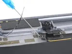
    • Use the pointed end of a spudger to disconnect the rear camera's press connector from its socket.

  71. XXA1JKYBZisNYXsv
    XXA1JKYBZisNYXsv
    GjRuoXsJLYJxAqdL
    • Use the pointed end of a spudger to disconnect the power button assembly's press connector from its socket.

  72. QqYkbSUWQqMmAAaS
    QqYkbSUWQqMmAAaS
    Dr2Saw3PUTEiSuJ6
    • Use the pointed end of a spudger to disconnect the volume buttons' press connector from its socket.

  73. VIJvDRTmFr53gtaG
    VIJvDRTmFr53gtaG
    RCujnUXPssagRKXA
    • Use a pair of tweezers to remove the sticker covering the ZIF connectors near the Lightning port.

  74. IboHDYIBMyOjpZ1C
    IboHDYIBMyOjpZ1C
    K6rkG2lRUjnREBMt
    • Use an opening pick to cut through the adhesive under the right ribbon cable next to the lower speaker (Lightning port oriented up) and detach it from the frame.

    • Be careful not to pull the ribbon cable out of the ZIF connector. Pulling the ribbon cable out while the ZIF connector locking flap is closed may damage the connection.

  75. vZn2GyXpKsxTUbIb
    vZn2GyXpKsxTUbIb
    FmPQCrNbDFAFK3kn
    • Use an opening pick to cut through the adhesive under the left ribbon cable next to the lower speaker and detach it from the frame.

    • Be careful not to pull the ribbon cable out of the ZIF connector. Pulling the ribbon cable out while the ZIF connector locking flap is closed may damage the connection.

  76. UsnGD2MLevsZwWWI
    UsnGD2MLevsZwWWI
    u3vvfafEX5w4Bncj
    • Use the pointed end of a spudger to flip up the hinged locking flap on the left ribbon cable ZIF connector.

  77. mpuAEJSyLFVfhDCa
    mpuAEJSyLFVfhDCa
    B15XNgJShoFrCSnU
    • Use the pointed end of a spudger to flip up the hinged locking flap on the right ribbon cable ZIF connector.

  78. CwPFKVS2uVfAmKDs
    CwPFKVS2uVfAmKDs
    ZZeaPh5qDJuSBhIv
    • Use a pair of tweezers to grip the left ribbon cable as close as possible to its contacts and pull the ribbon cable out of the ZIF connector.

  79. KuZKs224gDNCYteR
    KuZKs224gDNCYteR
    wZvBE5htT5SiYmHE
    • Use a pair of tweezers to grip the right ribbon cable as close as possible to its contacts and pull the ribbon cable out of the ZIF connector.

  80. CPYSeHFBGVEDQrJV
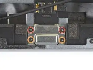
    • Remove the four Phillips screws securing the Lightning port:

    • Two 2.5 mm screws

    • Two 1.5 mm screws

  81. sP5AfiFfxmpoS1dv
    sP5AfiFfxmpoS1dv
    CmORt2AkOyNnI2Nt
    • This image shows the device with the logic board removed.

    • Strips of adhesive secure the logic board to the frame. In the next steps, you'll weaken and cut through the adhesive to detach the logic board from the frame.

  82. itbAwOTn2IexeEUM
    itbAwOTn2IexeEUM
    PW5AEnPOWNmXSbHa
    qVD44VTegjm6OwPu
    • Carefully turn the iPad over.

    • Many cables are loose at this point. Make sure no cables are bent or torn while turning the iPad over.

    • Heat an iOpener and apply it to the top, left, and bottom edges of the rear case for one minute on each edge.

  83. Rw4C3PbIRxVZPR3j
    Rw4C3PbIRxVZPR3j
    TncXv5JYErOFL5vQ
    • Use an opening pick to cut through the adhesive under the Lightning port ribbon cable to detach it from the frame.

  84. WVmYSoRkJOn4qS3B
    WVmYSoRkJOn4qS3B
    vSwLZFgDtbqYTffj
    • Use a pair of tweezers to lift up the smaller sticker to the left of the Lightning port (when the Lightning port is oriented up).

  85. MBmYa6yMBMNeKojK
    MBmYa6yMBMNeKojK
    fAgof2tDRITHvNm2
    • Use a pair of tweezers to lift up the larger sticker to the left of the Lightning port.

  86. SVbL1ostkooGGssY
    SVbL1ostkooGGssY
    AQWOiqWTYDRq6ZLr
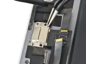
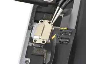
    • Use a pair of tweezers to grip the Lightning port by the bottom right screw hole.

    • Pull the Lightning port out of its recess.

  87. E4tETMTnvN1eBDGT
    • Apply a few drops of high-concentration isopropyl alcohol under the left edge of the upper logic board arm (Lightning port oriented down).

    • Wait thirty seconds for the isopropyl alcohol to weaken the adhesive under the upper logic board arm.

  88. oJOjLAWVfKnFQ3Zh
    oJOjLAWVfKnFQ3Zh
    qiBNDHwAd3KkYE1R
    • Use an opening pick to cut through the adhesive under the upper logic board arm and detach it from the frame.

    • The upper logic board arm is thin. Be careful not to tear it during this process.

    • It may help to grip the upper logic board arm with your fingers and peel it away from the frame.

    • Apply a few more drops of isopropyl alcohol under the logic board arm when it becomes difficult to detach from the frame.

  89. xyOLxXIrH2GbONCG
    xyOLxXIrH2GbONCG
    VbDFVcFg6NgvfNjI
    • Insert an opening pick about 0.5 inches (13 mm) under the top edge of the larger portion of the upper logic board arm.

    • Leave the opening pick under the upper logic board arm to prevent it from re-adhering to the frame.

  90. mEDSfeVYEGMHfJiN
    mEDSfeVYEGMHfJiN
    LaWWNGSkScYBiSub
    • Apply a few drops of high-concentration isopropyl alcohol to the right edge of the logic board.

  91. BxUMa3YVpTi4KZ3A
    BxUMa3YVpTi4KZ3A
    UIuGDZCySNKkVOAd
    • Apply a few drops of high-concentration isopropyl alcohol to the left edge of the logic board.

    • Wait one minute for the isopropyl alcohol to weaken the adhesive under the logic board.

  92. xI6Dw4QSCGebXcBu
    xI6Dw4QSCGebXcBu
    aXDPOCfygYXARFqf
    • Slide an opening pick about 0.5 inches (13 mm) under the top of the logic board's left side to cut through the adhesive.

    • Remove the opening pick.

  93. ed6Air366oXNkCCO
    ed6Air366oXNkCCO
    11GgsEGLxITJaYW2
    • Slide the opening pick about 0.5 inches (13 mm) under the logic board's left side next to the battery connector.

    • Remove the opening pick.

  94. MucNmvUdtdIbUjm4
    MucNmvUdtdIbUjm4
    Arfm3EyDdddZIVBC
    • Slide the opening pick about 0.5 inches (13 mm) under the logic board on the other side of the battery connector.

    • Remove the opening pick.

  95. JKbqniKtwYgeLTPE
    JKbqniKtwYgeLTPE
    JIlNmxkOHhGHo6Xa
    • Slide the opening pick about 0.5 inches (13 mm) under the bottom of the logic board's left side.

    • Remove the opening pick.

  96. ttkfqEqfqVIyxlEp
    ttkfqEqfqVIyxlEp
    W6uP6BaGXxlFEOi1
    • Remove the battery blocker from the logic board.

    • During reassembly, reinsert the battery blocker after you install the logic board into the device.

  97. VZOfkOPHv26S2Iqd
    VZOfkOPHv26S2Iqd
    SCOuhvbnUZsIMqMx
    • Remove the opening pick from the upper logic board arm.

  98. NkcimUc1t3rVKeIV
    NkcimUc1t3rVKeIV
    fMH2DGrdwjP1aq5d
    D5XMIVmpQoiojebA
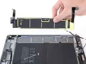
    • Remove the logic board from the frame.

    • If the logic board doesn't easily lift out of the frame, apply a few more drops of isopropyl alcohol to any stuck areas and use an opening pick to cut through more of the adhesive.

    • If there's any alcohol solution remaining in the device, carefully wipe it off or allow it to air dry before installing your logic board.

    • During reassembly, follow this guide if you are using a pre-cut adhesive card to secure the logic board to the frame.

  99. WUmgDvkYRcDKr1gf
    WUmgDvkYRcDKr1gf
    o16ViWif63CjpNvG
    • Take care not to puncture or bend the battery—a punctured or bent battery may leak dangerous chemicals or cause a thermal event.

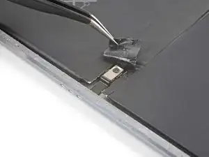
    • Use tweezers to gently lift the end of the black tape covering the mid-battery circuit board nearest the Smart Connector.

    • You only need to peel the tape back enough to reveal the connector underneath.

  100. XmXOFYVsAg4DKWWF
    XmXOFYVsAg4DKWWF
    pRpZpgR66MBTlbJe
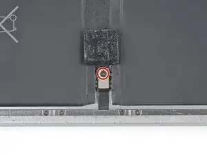
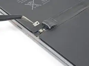
    • Remove the 1.7 mm Phillips screw holding the Smart Connector cable cover in place.

    • Remove the Smart Connector cable cover.

  101. TFbyFxZNdLSTslss
    TFbyFxZNdLSTslss
    dc6HoNhRJWfGqFju
    rNVRrTFevuBXuMSt
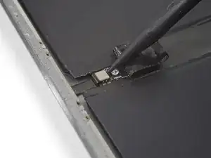
    • Use the point of a spudger to pry up and disconnect the Smart Connector from its socket between the battery cells.

    • Push the Smart Connector flex cable up and out of the way.

  102. NMrpvXG5KrxmcqSD
    NMrpvXG5KrxmcqSD
    VlDcdKVXqbqy6geQ
    NRSg6xmgVTjHiQDI
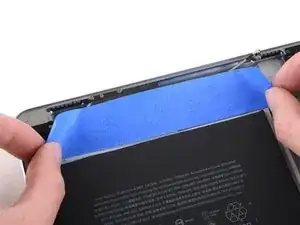
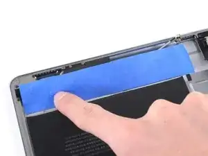
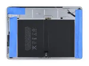
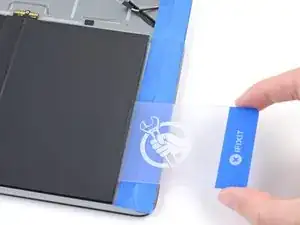
    • The next three steps detail how to mask off the iPad in preparation for the liquid adhesive remover. The tape will help block and absorb excess liquids, keeping major components safe.

    • Apply a piece of masking or painter's tape to the upper components. The edge of the tape should be close to, but not touching, the battery.

    • Press down on the tape so that it adheres firmly to the frame and components.

    These steps are a good precaution, but I’m not sure they’re necessary. I found that a very stingy application of acetone — just enough to draw a line along the card with a syringe was enough to separate the adhesive, without any issues of pooling.

    John Lasseter -

  103. JaQX1rI55kghJ2f2
    JaQX1rI55kghJ2f2
    GDiuUmPpElZv2sxC
    ZAkuP64CD1isOgKb
    • Repeat the taping procedure for the rear camera and volume button area.

  104. AsEwqMGygWMoiAv1
    AsEwqMGygWMoiAv1
    EJpk6XUvlG61Cm62
    DRCVEywkW4XoDDRQ
    • Repeat the taping procedure for the lower components.

  105. AhluDGIQ2BbAp1cM
    AhluDGIQ2BbAp1cM
    wCuvYDhaXEyJHTBX
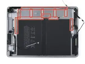
    • Once complete, the masking should look like the first image.

    • The adhesive remover may discolor or damage plastic components such as the speaker housings. Make sure you have applied the tape properly before you continue.

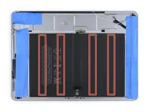
    • Four strips of strong adhesive hold the battery in place.

  106. trwQN2wA2ANpDW4F
    trwQN2wA2ANpDW4F
    MbLDRm6e5PpAOEA3
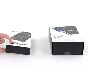
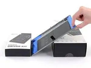
    • Prepare a work area where the iPad can rest in a tilted position, to allow adhesive remover to trickle down to the adhesive strips.

    • You can use books, boxes, etc. as long as they will not move.

  107. jbqNJOSLaBFTsbuV
    jbqNJOSLaBFTsbuV
    jA3noLBrJQDSIL4W
    • iFixit adhesive remover contains acetone, a mild skin and eye irritant.

    • Wear eye protection when handling and applying the adhesive remover. (Eye protection is included in your kit.)

    • Do not wear contact lenses without eye protection.

    • Protective gloves are highly recommended beyond this step, as the dissolved adhesive will be very tacky and hard to wash off.

  108. YCIanYLWJKXwnBoI
    YCIanYLWJKXwnBoI
    cUErXlHi1IQgakXG
    gb1HHijWVBXsTyGc
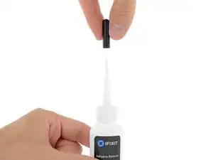
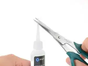
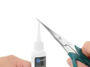
    • Pull off the black rubber stopper from your bottle of adhesive remover.

    • Twist to loosen or remove the bottle cap before you cut the applicator tip.

    • This unseals the bottle and allows the pressure to equalize before you cut the applicator tip. If you skip this step, the adhesive remover may spray out unexpectedly when the tip is cut.

    • Use scissors to cut off the sealed tip of the applicator.

    • Cutting close to the narrow tip will give you better control so you can apply the adhesive remover in small amounts.

    • Twist and close the bottle cap securely before you proceed further.

  109. Kc4RWKKsmmhtbkVq
    Kc4RWKKsmmhtbkVq
    hK1VrcqxD6uUWOCb
    gaL2cMhfRKAUC5Ax
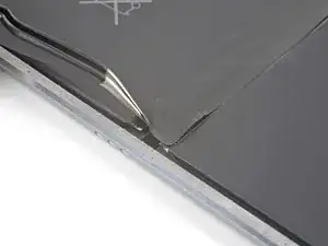
    • Carefully insert a plastic card under the bottom right corner of the battery.

    • Slowly slide the plastic card across the bottom edge of the battery to make a gap for the liquid adhesive remover.

    • At this point, you do not need to push the card very deep under the battery. 0.5 inches (13 mm) is more than sufficient.

    • While some bending of the battery pack will be inevitable, try not to form any sharp creases, which will compromise the battery structure and potentially trigger a fire hazard.

  110. EjqbZNIpDAc2ujlo
    EjqbZNIpDAc2ujlo
    fHnOaCFbERbJaFSw
    aefBkEBHwX3yZneN
    • Tilt the bottom of the iPad up.

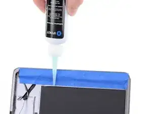
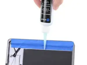
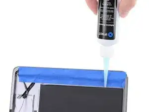
    • Apply a few drops of adhesive remover evenly along the elevated edge of the battery.

    • A little bit goes a long way, so start with a very small amount. You can always add more later if needed. Applying the solvent in small amounts helps prevent unwanted leaks.

  111. WX3SKgPNEPbJOy12
    • Rest the iPad in a slanted position, bottom edge up, and wait 2-3 minutes to allow the adhesive remover to penetrate and soften the first adhesive strip.

  112. VuSc6OhFT3iCKDmp
    VuSc6OhFT3iCKDmp
    VpAi54NCRCKlrTL1
    dpuAdUsTBZs6VRiF
    • Slide a plastic card into the bottom edge of the battery.

    • Push the card in slowly and firmly. Gently wiggle and twist the card to help it slice through the adhesive.

    • If you are struggling, tilt the iPad, apply a few more drops of adhesive remover and wait a minute before trying again.

  113. U3Iu5FoxYgdrhWfw
    U3Iu5FoxYgdrhWfw
    cID6x5Y5F2CILFJw
    iqDuZGhC4AmsbeEq
    • You can also approach the adhesive strip with the plastic card from battery's other bottom corner.

    • Continue slicing until you have separated the battery from the first adhesive strip.

  114. ApehUOxedgYrjcVO
    ApehUOxedgYrjcVO
    HRNK2vlEEOaF625m
    bmTpEBRVXWpMJrLs
    • Tilt the bottom of the iPad up.

    • Reapply adhesive remover into the gap for the second adhesive strip, located deeper underneath the bottom battery cell.

    • Repeat the application, waiting, and slicing process until the second adhesive strip is separated from the battery.

  115. QYShIBjDSUtVArqc
    QYShIBjDSUtVArqc
    rlQK1Lt5FyUcBLHa
    JlGEbZWpoIXQKSGi
    • Slide an opening pick under the top edge of the battery, creating a gap large enough for a plastic card.

    • Insert a plastic card under the top edge and slide it across the entire length, creating a gap for the adhesive remover.

  116. WBCcJyvp4kKifcty
    WBCcJyvp4kKifcty
    riAjWTvkh1wPKPDh
    xmbv5KHcifMKGMBK
    • Apply adhesive remover into the gap to help weaken the third adhesive strip.

  117. nDXbWshLAqDZUQCt
    • Rest the iPad in a slanted position, top edge up, for 2-3 minutes to allow the adhesive remover to weaken the third strip.

  118. YDHBoaChQDIiU6Ic
    YDHBoaChQDIiU6Ic
    GYNOsWHplZjqvEVb
    pwoQH4GHWFSyTSBQ
    • Use a plastic card to slice through the third adhesive strip.

    • If you are struggling, tilt the iPad, apply a few more drops of adhesive remover, and wait a minute before trying again.

  119. E2HCcGc1YGoGnKOV
    E2HCcGc1YGoGnKOV
    HYbgPL62hPrkEHpW
    iprhZJJ1VS5DbNcw
    • Repeat the application, waiting, and slicing process to release the last adhesive strip located deeper underneath the top battery cell.

  120. 2BCh1HWNPNL3BZIc
    2BCh1HWNPNL3BZIc
    oAApxmHXqHPTLMwY
    3WOCvUcny3CYqH43
    • Use the plastic card or your fingers to flip the bottom half of the battery over so that it rests on top of the upper half.

  121. iXqyeWKAMxSAHPEI
    iXqyeWKAMxSAHPEI
    Jr3b2HIDYZuEoqSC
    • The end of the mid-battery circuit board closer to the Smart Connector is held down with adhesive.

    • Slide an opening pick underneath the mid-battery circuit board, near the Smart Connector.

    • Carefully slice underneath the board around the post to release the board from the rear case.

  122. 1rGtRGq6rRdvZMwm
    1rGtRGq6rRdvZMwm
    uYaHMXtqfunyDV3A
    • Slide the long edge of a plastic card about 0.5 inches (13 mm) under the center of the mid-battery circuit board to cut through the remaining adhesive.

  123. CIkHSwTNF4ybMUCr
    • Lift and remove the battery from the frame.

    • Two screw posts position the battery on the frame—one near the Smart Connector and one under the battery connector.

  124. CKqoOxDcKcVJUYFB
    CKqoOxDcKcVJUYFB
    qtRddFIBXWlHia5i
    • The next steps detail how to install a new battery. Never reinstall a used battery.

    • Thoroughly clean the back case of all adhesive residue.

    • Apply adhesive remover or high concentration (over 90%) isopropyl alcohol to the residue.

    • Use an opening tool to scrape and loosen the residue.

    • Be sure to wipe the residue away in one direction to prevent smearing.

    • It is easier to wipe off the residue when it is sufficiently soaked. Once it starts drying up, the residue becomes incredibly tacky.

    • If you used adhesive remover, be sure to wipe the surface down with isopropyl alcohol to remove any adhesive remover residue.

    • You can remove the masking tape as well as any protective gear once you are done cleaning.

  125. mHTNNUbtXgHwuLL1
    mHTNNUbtXgHwuLL1
    J151TugNqGeS2WTm
    • Place the replacement battery pack so that the two screw posts line up with their holes on the mid-battery circuit board and battery connector.

  126. JoRE35T1eAJjuQGe
    JoRE35T1eAJjuQGe
    eulMXFUowBdTcWVg
    • Lift the bottom edge of the battery up slightly.

    • Do not hinge the battery beyond 45 degrees, or you risk damaging the inter-cell connectors.

    • Use tweezers or your fingers to peel the single clear plastic covering off of the entire bottom side of the battery.

    • At this point, the battery's four adhesive strips are exposed. Be careful handling the battery and try not to touch the strips.

    • Align the battery such that it falls in place with the screw post near the Smart Connector.

    • Be sure not to trap the Smart Connector cable underneath the battery.

    • Gently lay the battery down into its recess and press it firmly into place.

    • For optimal performance, calibrate your newly installed battery after completing this guide: Charge it to 100% and keep charging it for at least 2 more hours. Then use your device until it shuts off due to low battery. Finally, charge it uninterrupted to 100%.

Conclusion

To reassemble your device, follow these instructions in reverse order.

Take your e-waste to an R2 or e-Stewards certified recycler.

Repair didn’t go as planned? Check out our iPad Pro 9.7” Answers Community for troubleshooting help.

Kyle Smith

Member since: 01/02/21

40639 Reputation

14 comments

That’s an excellent guide! I had to replace both the battery and the display. The iPad seems fixed and boots but shuts down after 3min/180s due to "no successful checkins from com.apple.thermalmonitord since wake". The other services listed in the dump all report successful checkins. I have no idea whether that rather indicates something went wrong with the battery replacement or with the display exchange (and associated home button transfer). A hard DFU didn’t help.

frightanic.com -

Did you ever get this fixed? I’m running into the same thing.

Joseph Ferrare -

Hello, I tap the home button, Apple is very picky about the exchange. Just try the original home button if it is still available.

Michael Brandt -

Used this guide it is missing the part where you need to remove the screw from the battery post. Post needs to be reissued. I have now tried 3 OEM batteries including reinstalling the existing one and all cause the iPad to go into a restart loop I think iOS 14 devices are firmware locked as all show 100mAh on Coconut Plus which probably causes the restart loops. Even completed hard reset and total factory reset however still stuck in restart loop

SpideRaY -

Did you manage to fix this? I got the same result.
Joseph Ferrare -

Nice work on this! I’m still reeling a bit from how complicated this operation is, as I expected something much simpler. Other than the taping (which I didn’t need to do), I found every step to be absolutely necessary, just as you described. Thanks.

John Lasseter -

my ipad battery drained even faster after i replaced it with a new battery, may i know why?

ex abc -

Sorry to hear about the trouble! If you bought an iFixit battery, please contact our customer support team and they would be happy to assist you.

Adam O'Camb -

I am sure that this repair guide was carried way to far. After opening the iPad and removing the batterie connector screw, the logic board cover and the display itself there is NO need to remove any other part on top. Only the screw for the smart connector needs then to be removed. So no antenna, no lighting connector and even no logic board or every other component needs to be removed.

Yes, only lifting up the logic board is a bit more tricky when connecting the new battery and it might even be more dangerous for the logic board than removing every component from the backplate. But from my point of view the risk taken is much greater following this guide than as I described since each (and here there are plenty unnecessary) step on top also leads into a higher risk. Since the glued down logic board is even totally removed the risk of bending it too much and braking it is still present.
Half of the steps are just useless which only leads into a higher risk of breaking something. In the end: just be careful.
Timo Mahringer -

Hi Timo,

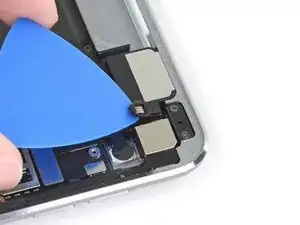
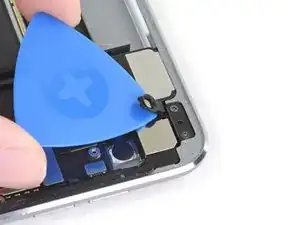
Thanks for your input! Your points are valid—the more you disassemble a device, the higher the chance for damage. In the past, our iPad guides actually did what you suggested; we instructed people to pry up the logic board and slide the battery connector out. Unfortunately, Apple began using stronger adhesives to hold the logic board. Flexing the board too much can cause solder joints on surface mount components to break, causing problems. We weighed the options during the guide writing process, and decided to revise with a longer, gentler approach. We're always on the lookout for better solutions, and will update the guide when we find them!
Arthur Shi -

I was wondering the same thing. Regardless of what method you use, a LOT of care is required. It seems like if you skip the logic board stuff you can probably do the repair in less than an hour. I am curious if the use of more heat on the logic board adhesive (from the back of the ipad) would be helpful.

joshcorey -

Too late for me! I managed to do all the steps and installed a new battery – but after assembly, the screen turns on (white), starts flashing and the iPad beeps. Then turns off. Switching on: the same.

I checked all connectors, display lines... Cannot see any injuries :-(

Any ideas?

Bernd Löhr -

Not worth it. I’m doing a lot of repairs myself but had no inclination to go through this complicated process, so I gave the iPad to a professional repair shop (Apple certified).

As already mentioned in other comments the iPad came back with a wildly inaccurate charge indication. This seems due to the fact that the battery management system (BMS) isn’t part of the battery itself and can’t be properly reset for use with a new battery by a third party.

When reading battery parameters with coconutBattery only the cycle counter was reset, and ominously enough the indicated actual capacity was exactly the design value. SN and life cycle data were from the old battery. Charge/discharge rates weren’t shown properly and performance was a far cry from a new iPad.

Returned the iPad to the shop; they acknowledged the fault, even tried a battery from a different supplier but couldn’t fix it. Eventually they gave me a full refund.

Note: Apple already list this model as “vintage” and don’t offer battery change for it anymore.

zapotron -

Awesome instructions! Worked like a charm but I would hate to go through this again!

Jennie Boudreau -