Introduction

Use this guide to replace the screen in your iPad Pro 12.9" 5th Gen.

The screen consists of the display and the top sensor assembly. If you don't transfer the top sensor assembly, you will lose Face ID and True Tone.

This guide is written with an A2379 (Wi-Fi and LTE with mmWave) model iPad Pro. If you have the Wi‑Fi only model, use this guide as a general reference, but you may need to perform extra disassembly not covered in this guide.

Some photos show the battery connector blocked with two card strips. While this is an optional method, it's more reliable to fully discharge the battery. Ignore this visual discrepancy as you work through the guide.

  1. L2bPbPROcvLjn6wk
    • Allow your iPad's battery to drain below 25% before starting this repair. A charged battery may catch fire if damaged during the repair.

    • If your battery is swollen, take appropriate precautions.

    • Unplug any cables and fully shut down your iPad.

  2. BtVWQ52HEFXlHOYx
    • Apply a heated iOpener to the right edge of the screen for two minutes.

    • A hair dryer, heat gun, or hot plate may also be used, but be careful not to overheat the iPad—the screen and internal battery are susceptible to heat damage.

  3. tt5jYCwYT45ASavn
    tt5jYCwYT45ASavn
    MYbpOAXdavgXYfB4
    51hXGvUKBCJcfi6J
    • The next three steps demonstrate the Anti-Clamp, a tool we designed to make the opening procedure easier. If you aren't using the Anti-Clamp, skip down three steps for an alternate method.

    • For complete instructions on how to use the Anti-Clamp, check out this guide.

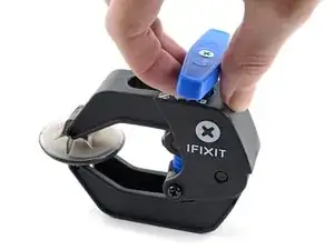
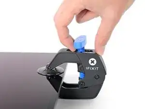
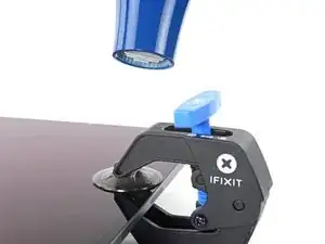
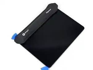
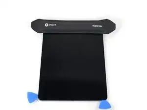
    • Pull the blue handle backwards to unlock the Anti-Clamp's arms.

    • Place an object under your iPad so it rests level between the suction cups.

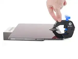
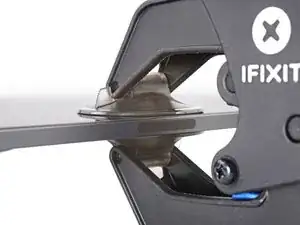
    • Position the suction cups near the middle of the right edge—one on the top, and one on the bottom.

    • Hold the bottom of the Anti-Clamp steady and firmly press down on the top cup to apply suction.

    • If you find that the surface of your iPad is too slippery for the Anti-Clamp to hold onto, use tape to create a grippier surface.

  4. K2cPoWCO2OnFlRhi
    K2cPoWCO2OnFlRhi
    1Q6V1Gmjs4sUR2o1
    6UBAGNFFWRGrr61Z
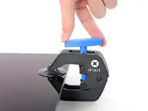
    • Pull the blue handle forward to lock the arms.

    • Turn the handle clockwise 360 degrees or until the cups start to stretch.

    • Make sure the suction cups remain aligned with each other. If they begin to slip out of alignment, loosen the suction cups slightly and realign the arms.

  5. OMQOXpgEZKWZiCCn
    OMQOXpgEZKWZiCCn
    YnMcUe6aGvXNGDKe
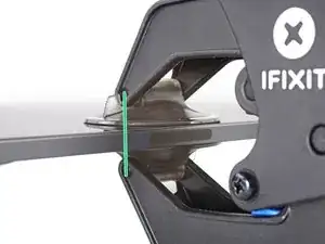
    • Wait one minute to give the adhesive a chance to release and present an opening gap.

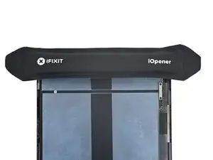
    • If your screen isn't getting hot enough, you can use a hair dryer to heat along the right edge of the iPad.

    • For complete instructions on how to use a hair dryer, check out this guide.

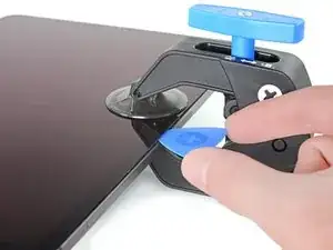
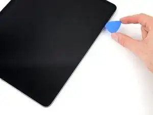
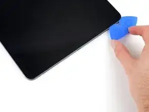
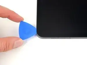
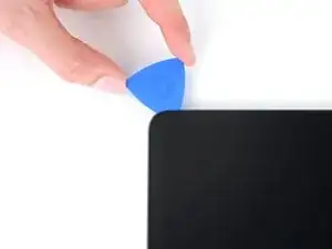
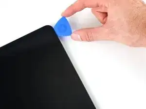
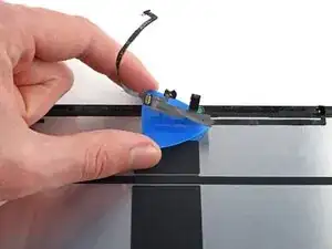
    • Insert an opening pick under the screen when the Anti-Clamp creates a large enough gap.

    • If the Anti-Clamp doesn't create a sufficient gap, apply more heat to the area and rotate the handle clockwise half a turn.

    • Don't crank more than a half a turn at a time, and wait one minute between turns. Let the Anti-Clamp and time do the work for you.

    • Skip the next step.

  6. t3B3cJNOAAtOwhdX
    t3B3cJNOAAtOwhdX
    YPBU6mDj1CBdSDPt
    PHBvtyicBV3YINLQ
    • If your screen is badly cracked, covering it with a layer of clear packing tape may allow the suction cup to adhere. Alternatively, very strong tape may be used instead of the suction cup. If all else fails, you can superglue the suction cup to the broken display.

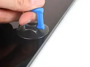
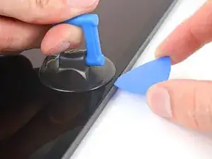
    • Apply a suction handle to the screen as close to the center of the right edge as possible.

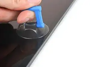
    • Pull up on the suction handle with a strong, steady force to create a small gap between the frame and screen.

    • The large screen is very fragile. Only create a gap big enough to insert an opening pick.

    • If you're having trouble making a gap, reapply a heated iOpener to the right edge for two minutes.

    • Insert an opening pick into the gap.

    • Don't insert the pick more than 5 mm to avoid damaging the screen.

  7. g1QNuqZKk3G2ihYp
    g1QNuqZKk3G2ihYp
    NNvUXStSSh5csOfp
    COWMOPL3l5rPGkqf
    • There are two 2 cm-long magnets along the right edge of the screen. Don't insert your opening pick more than 2 mm to avoid damaging the screen in these locations:

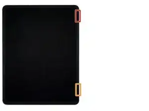
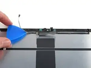
    • The first magnet begins about 3 cm from the top of the iPad.

    • The second magnet begins about 3 cm from the bottom of the iPad.

    • Everywhere else, don't insert your opening pick more than 5 mm.

  8. BMfIJOkWqkI5Y5ji
    BMfIJOkWqkI5Y5ji
    MxSwT6kWHC5OBK4D
    EYeM4uqTvx4VgmiY
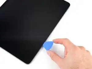
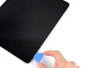
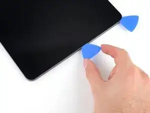
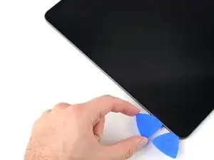
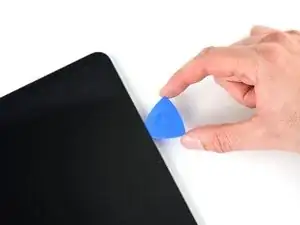
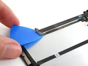
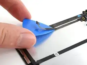
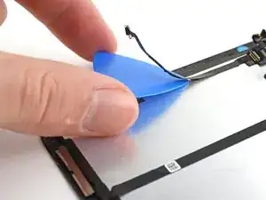
    • Slide your opening pick along the right edge of the screen to separate the adhesive.

    • Angle your pick downward and insert up to a 2 mm depth near the magnet cutouts and 5 mm everywhere else.

    • Leave the pick inserted in the bottom right corner before continuing.

  9. fW2Vs5bsRXITJmR2
    fW2Vs5bsRXITJmR2
    PXijmWSEWdAuq2mN
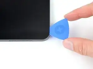
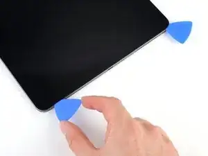
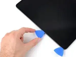
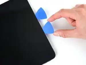
    • Slide your opening pick around the bottom right corner of the screen to separate the adhesive.

    • Leave your pick in the bottom right corner to prevent the adhesive from resealing.

  10. DxLQcapNWYoxNQeH
    • Apply a heated iOpener to the bottom edge of the screen for two minutes.

  11. HJOqXNPfIDyZTWC5
    HJOqXNPfIDyZTWC5
    EJaydKJYSYMkQNgy
    wghWd1KIg5XaavKP
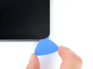
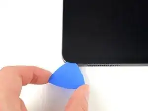
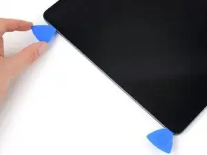
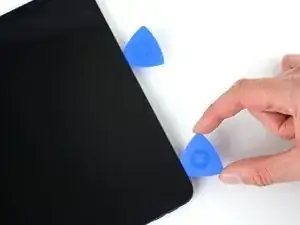
    • Insert a second opening pick under the bottom right corner of the screen.

    • Don't insert your opening pick more than 5 mm.

    • Slide your pick to the bottom left corner to separate the bottom adhesive.

  12. hXYHYZhLkwOLKlDe
    hXYHYZhLkwOLKlDe
    ITG4XbAQC1SxX2nJ
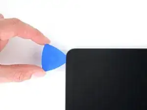
    • Rotate your opening pick around the bottom left corner of the screen.

    • Leave your pick in the bottom left corner to prevent the adhesive from resealing.

  13. cQfrqDNkBRTHoLEo
    • Apply a heated iOpener to the left edge of the screen for two minutes.

  14. a2a1SGxPOF5ca13k
    a2a1SGxPOF5ca13k
    3YvJQTKTF43RgqvE
    • There are four 2 cm-long cutouts along the left edge of the screen where the adhesive is very thin. Don’t insert your opening pick more than 2 mm in these locations to avoid damaging the display:

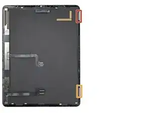
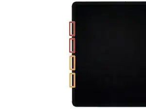
    • The upper cutouts begin at 4 cm and 6 cm from the top of the frame.

    • The bottom cutouts begin at 4 cm and 6 cm from the bottom of the frame.

    • Everywhere else, don't insert your opening pick more than 5 mm.

  15. 5OyIjg1GodfJD1IP
    5OyIjg1GodfJD1IP
    FeAMjuE5xOTpxXOA
    vDBOZxaNZ4kdVhRS
    • Insert a third opening pick under the bottom left corner of the screen.

    • Slide your pick to the top left corner to slice the left adhesive, making sure to avoid the cutouts shown in the previous step.

    • Leave the pick inserted in the top left corner before continuing.

  16. ZSmIFBdEiCsOAUw6
    ZSmIFBdEiCsOAUw6
    t3O3yHay1c1aLxbh
    • Slide your opening pick around the top left corner of the screen.

    • Leave your pick in the top left corner to prevent the adhesive from resealing.

  17. 5nCU2M6Q6FhObwcO
    • Apply a heated iOpener to the top edge of the screen for two minutes.

  18. N5UOq2gJCDKqUiB6
    N5UOq2gJCDKqUiB6
    q6GhbZOqUB6GVnwO
    NF4doygsAukZ1ZbO
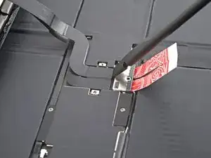
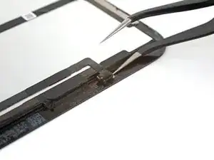
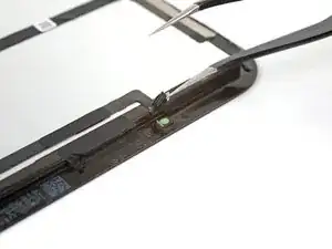
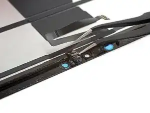
    • While the top edge adhesive softens, note the following:

    • There are two ambient light sensors near the corners. Don't insert your pick more than 1 mm here.

    • The front-facing camera and additional sensors are in the center of the top edge. Don't insert your pick here—there is less than 1 mm of adhesive and you may damage the components.

    • For everywhere else, don't insert your pick more than 5 mm to avoid damaging the screen.

  19. JQSUSVHpYUAWSMnt
    JQSUSVHpYUAWSMnt
    fuBqKciryhaCXtA2
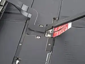
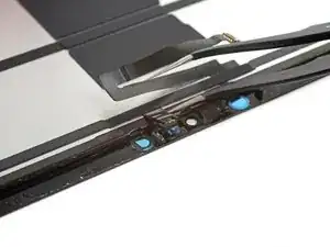
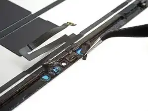
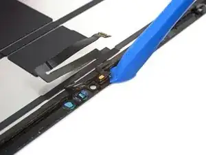
    • Slide your opening pick toward the top right edge, stopping just before the camera assembly.

    • If you slide any farther, you risk damaging the camera's sensors.

    • Leave your pick inserted before continuing.

  20. LXUeQXbZu5IbxJaU
    LXUeQXbZu5IbxJaU
    gBiI5RHhiXvPDUKK
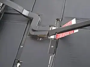
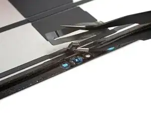
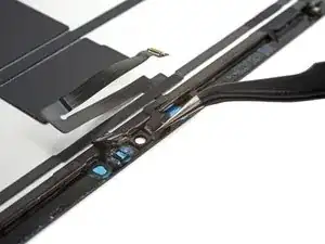
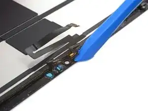
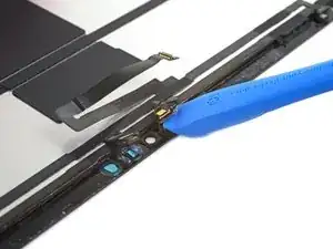
    • Insert a new opening pick on the other side of the camera assembly, about 4 cm from the previous pick.

    • Slide your pick to the top right corner to slice the remaining adhesive.

  21. WEn2BtDZMgAeTHS4
    WEn2BtDZMgAeTHS4
    Cwcongxk1qQcvna1
    i6TNiahHGc3fBVPu
    • Don't fully remove the screen, as it's attached by several cables.

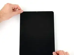
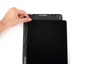
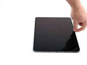
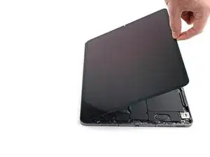
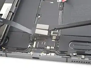
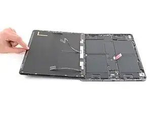
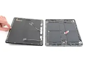
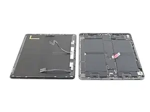
    • Grab two opposing corners of the screen and lift up to separate it from the frame.

    • If the screen feels stuck, slide your opening picks around the perimeter to separate any remaining adhesive. Pay attention to sensitive areas shown in previous steps.

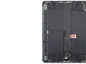
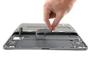
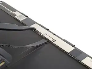
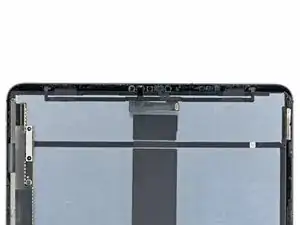
    • Shift the screen towards the bottom right corner of the frame until the ribbon cable near the top edge is uncovered.

  22. 4BDoClcCifNZNnHs
    • Throughout this guide, keep track of each screw and reinstall it exactly where it came from.

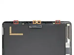
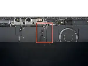
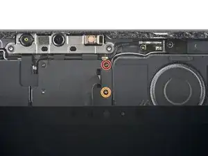
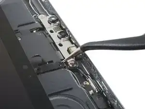
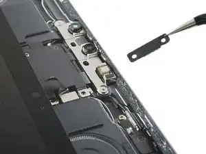
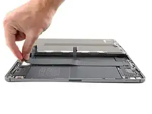
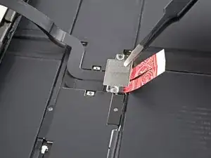
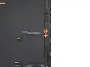
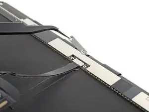
    • Use a Phillips screwdriver to remove the two screws securing the upper cable shield:

    • One 1.8 mm-long screw

    • One 1.4 mm-long screw

    • During reassembly, this is a good point to power on your iPad and test all functions before sealing it up. Be sure to power your iPad back down before you continue working.

  23. HJExQIpBLIHF6HOF
    HJExQIpBLIHF6HOF
    cATwmFhp6SEL3h5e
    • Use tweezers or your fingers to grab and remove the upper cable shield.

  24. oeUCs2KZqOUR1vdj
    oeUCs2KZqOUR1vdj
    INdyJvx44nBRNQtp
    • Use the tip of a spudger to pry up and disconnect the upper sensors press connector.

    • To re-attach press connectors, carefully align and press down on one side until it clicks into place, then repeat on the other side. Don't press down on the middle. If the connector is misaligned, the pins can bend and cause permanent damage.

  25. Rgg6bWUIqO3LO3hK
    Rgg6bWUIqO3LO3hK
    y3pAhN3QjJgoom2X
    61iksEhq2emJHwRo
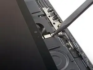
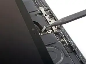
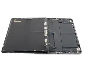
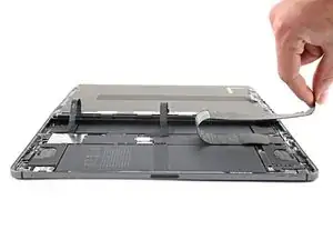
    • Grip the right edge of the screen and open it like a book.

    • Don't pull up on the screen—the screen cables are still attached.

    • Lay the screen down over the left edge of the iPad.

    • Be careful not to strain the screen cables.

  26. 2pZbN5drDq3FFBgw
    2pZbN5drDq3FFBgw
    sxtbqWCGnPeOmdrm
    VMx2IMWkBNo2vmY4
    • The logic board cover is lightly adhered to the logic board.

    • Peel the cover off of the logic board to remove it.

  27. hZHVqJdyQo2OxfEr
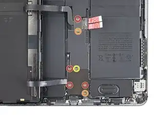
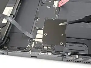
    • Use a Phillips screwdriver to remove the seven screws securing the top and bottom display brackets:

    • Four 1.1 mm-long screws

    • Two 2.0 mm-long screws

    • One 1.0 mm-long screw

  28. onaowBNOVMs4NREg
    onaowBNOVMs4NREg
    jN5WBCUA5TDYI12n
    GwvuM6GVIkStOlFy
    • Use tweezers, or your fingers, to remove the top and bottom display brackets.

  29. XExqAmFOoFVuA1U2
    XExqAmFOoFVuA1U2
    IxUgOE4dcvPnioyd
    pyqPECRPhrKFTXR3
    • Use a spudger to pry up and disconnect the two bottom display cable press connectors.

  30. gCLpHCEtl1oyCxRg
    gCLpHCEtl1oyCxRg
    xLwH5K1aJtB4G5ew
    fUXF2cNcgWPji1lI
    • Use a spudger to pry up and disconnect the two top display cable press connectors.

  31. RRgrdFSBGxDH4JPO
    RRgrdFSBGxDH4JPO
    Ip2OClOGLL5xgyvD
    yDYCACLpY6BOEcxw
    • Remove the screen.

  32. uxWgfWeVusSJfVDA
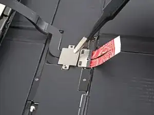
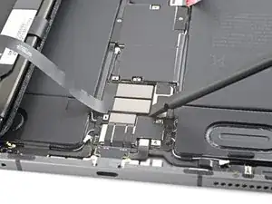
    • Use a Phillips screwdriver to remove the two 1.2 mm-long screws securing the display cable bracket.

  33. IM2FHW2lfBpafWpy
    IM2FHW2lfBpafWpy
    1BUCSkrlASe2MPFf
    • Remove the display cable bracket.

  34. BHaXOxtduHwaFiAd
    BHaXOxtduHwaFiAd
    r5JxEMXWyxcfLMSO
    • Use a spudger to pry up and disconnect the display cable press connector on the screen.

  35. WMspXgKVQEQOaIBK
    WMspXgKVQEQOaIBK
    CPwlTbqDYnrHrUJh
    uW5vMiEoP4TqqvfY
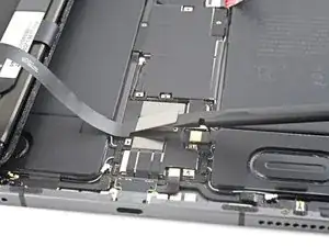
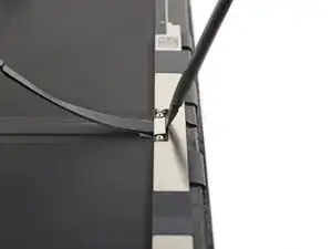
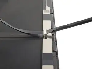
    • Use tweezers, or your fingers, to peel the display cable off its opposing cable.

    • Remove the display cable.

    • Set the cable aside. You'll use it during reassembly.

  36. xDEkCVt5hOxQEKGR
    xDEkCVt5hOxQEKGR
    gukUbNQyQSIYGxrq
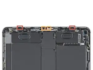
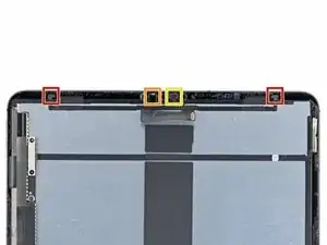
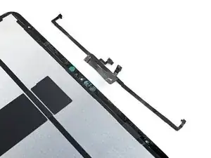
    • Your top sensor assembly is composed of four sensors:

    • Two ambient light sensors

    • One proximity sensor

    • One microphone

    • You'll need to separate each sensor from the screen before removing the entire assembly.

  37. CRBwh5NfDvNtTKjW
  38. kTuGWQbtjLWnPlCM
    kTuGWQbtjLWnPlCM
    AlCU5kFf4IZIapgy
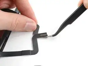
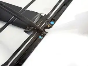
    • Insert one arm of your angled tweezers between the ambient light sensor and the screen.

    • Pry up to separate the sensor from the screen.

    • This might take significant force.

    • Repeat this procedure for the other ambient light sensor.

  39. vglPXlT4CSBK2jHR
    vglPXlT4CSBK2jHR
    FAwRrkmYN1YfPiaJ
    1EKZobURjOtClLP5
    • Be very careful during this step, as the sensor cable can tear. Work slowly and apply more heat if you encounter resistance.

    • Insert one arm of your angled tweezers between the proximity sensor cable and the screen.

    • Slide the tweezers toward the screen while prying to separate the sensor from the screen.

    • This might take significant force and multiple iOpener heating cycles.

  40. 3dNATt5WvL6rRhct
    3dNATt5WvL6rRhct
    qurIAfVK4Y41IsfF
    • Peel off any tape covering the microphone.

    • Set the tape aside. You'll use it during reassembly.

  41. HIxXglCBeCXUu6kV
    HIxXglCBeCXUu6kV
    VMlGTPTxeZwBjoUA
    wWQRPFX42jaLQ1mR
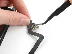
    • Slide an opening tool under the microphone to separate its adhesive.

    • Pry up to separate the microphone from the screen.

  42. MfDCXPWd5CMvmPDT
    MfDCXPWd5CMvmPDT
    cXHYPbdRqcEljYOE
    J4INIHOVPreXXyA4
    • Slide an opening pick under the top sensor assembly cable to separate it from the screen.

  43. NVMLM2wZMDPQYSMX
    NVMLM2wZMDPQYSMX
    YETPIGBMGQirD2gD
    1GCVExBEECdosAWJ
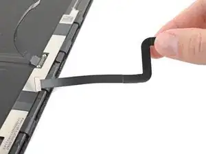
    • Continue sliding your opening pick along the top sensor assembly until its completely separated from the screen.

    • Remove the top sensor assembly.

  44. ThjMelpSSFcs5FEM
    • During reassembly, perform the following:

    • Align the top sensor assembly on your replacement screen.

    • Use Tesa tape, or similar double-sided tape, to secure the cables to the screen.

    • Use E6000 adhesive, or similar adhesive, to secure the sensors to their cutouts on the screen.

Conclusion

To reassemble your device, follow these instructions in reverse order.

Compare your new replacement part to the original part—you may need to transfer remaining components or remove adhesive backings from the new part before you install it.

Take your e-waste to an R2 or e-Stewards certified recycler.

Repair didn’t go as planned? Try some basic troubleshooting, or ask our iPad 12.9" 5th Generation Answers community for help.

Alex Diaz-Kokaisl

Member since: 16/01/22

117875 Reputation

4 comments

Where do you suggest ordering the replacement screen parts to complete the repair?

Michael Bailey -

Hi Michael.

I apologize that we don't sell the screen; we should at some point! For sourcing a genuine, OEM part, that's going to be a tricky. You can try your luck on 3rd party websites (I'm not sure I can in good faith endorse any specific ones), or you can find a salvaged part off of resellers like eBay. Use your best judgement when making purchases from any of these retailers.

Alex Diaz-Kokaisl -

Can the sensor assembly just be replaced as opposed to reusing the old one? Or it is like the Face ID on an iPhone?

rcr6264 -

Hi there.

Unfortunately, as stated in the introduction, the sensor assembly is paired to the logic board. You will lose Face ID and True Tone if you don't transfer the original assembly.

Alex Diaz-Kokaisl -