Introduction
Follow this guide to replace the logic board in your iPad Pro 11" 3rd gen.
The logic board in your iPad Pro is paired to the Face ID hardware. Replacing it will disable Face ID.
This guide is written with an A2301 (cellular + mmWave) model iPad Pro. If you're fixing a Wi-Fi model, you can still use this guide—there will be some visual discrepancies, and you'll need to skip the steps related to the cellular antennas.
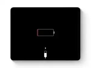
Some photos show the battery connector blocked with two card strips. While this is an optional method, it's more reliable to fully discharge the battery. Ignore this visual discrepancy as you work through the guide.
-
-
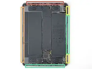
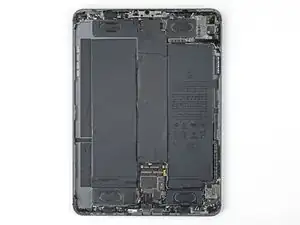
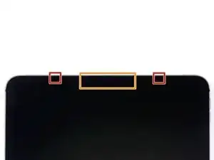
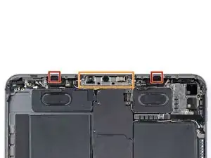
Camera module, ambient light sensors, proximity senor, and front microphone
-
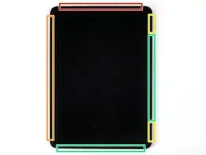
Display cables
-
Screen magnets
-
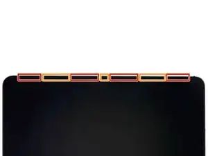
LCD edges
-
-
-
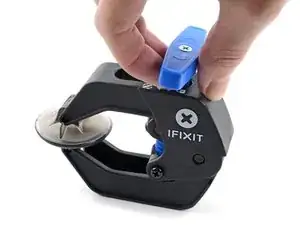
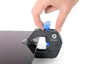
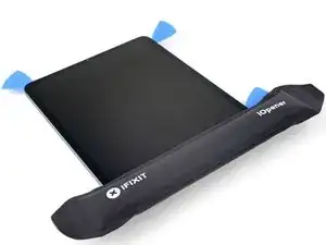
Pull the blue handle backward to unlock the Anti-Clamp's arms.
-
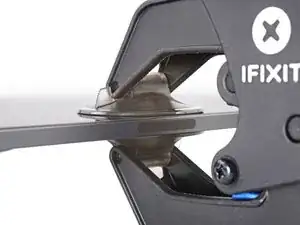
Place an object under your iPad so it rests level between the suction cups.
-
Position the suction cups near the middle of the right edge—one on the top, and one on the bottom.
-
Hold the bottom of the Anti-Clamp steady and firmly press down on the top cup to apply suction.
-
-
-
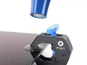
Pull the blue handle forward to lock the arms.
-
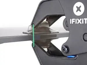
Turn the handle clockwise 360 degrees or until the cups start to stretch.
-
Make sure the suction cups remain aligned with each other. If they begin to slip out of alignment, loosen the suction cups slightly and realign the arms.
-
-
-
Wait one minute to give the adhesive a chance to release and present an opening gap.
-
If your screen isn't getting hot enough, you can use a hair dryer to heat along the right edge of the iPad.
-
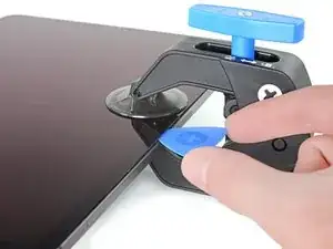
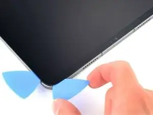
Insert an opening pick under the screen when the Anti-Clamp creates a large enough gap.
-
Skip the next step.
-
-
-
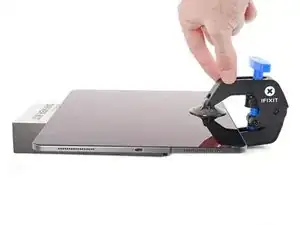
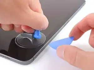
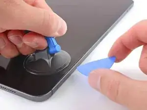
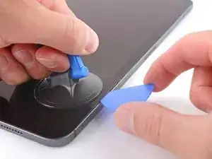
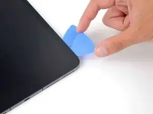
Apply a suction handle to the right edge of the screen, about 5 cm from the bottom edge.
-
Pull up on the suction handle with firm, constant pressure to create a gap just small enough to insert an opening pick.
-
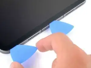
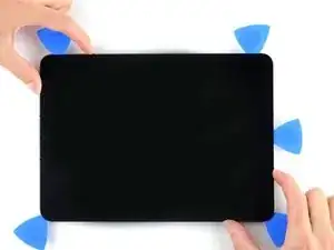
Insert the tip of an opening pick into the gap.
-
-
-
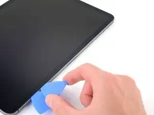
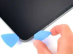
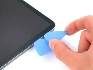
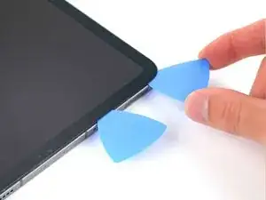
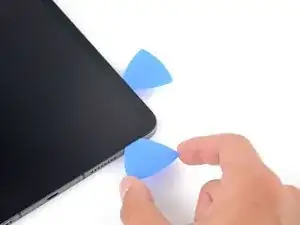
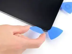
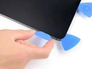
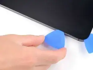
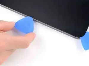
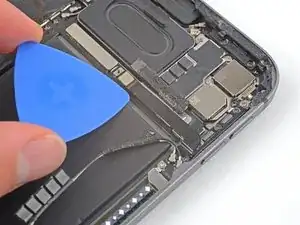
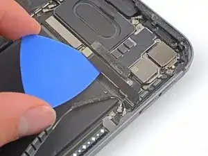
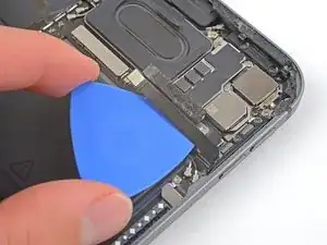
Insert a new opening pick in the gap you just created.
-
Slide the pick along the right edge to separate the adhesive.
-
Leave the pick in the top right corner to prevent the adhesive from re-sealing.
-
-
-
Don't insert an opening pick more than 2 mm near the top left and right edges or you'll damage the ambient light sensors.
-
Don't insert an opening pick more than 1 mm near the middle of the top edge or you'll damage the camera module, proximity sensor, and front microphone.
-
-
-
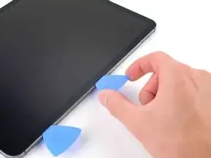
Insert a new opening pick in the gap you just created.
-
Slide the pick along the top right edge, stopping when you reach the right ambient light sensor.
-
Leave the pick in to prevent the adhesive from re-sealing.
-
-
-
Insert a new opening pick to the right of the ambient light sensor.
-
Slide the pick along the middle section of the top edge, stopping when you reach the left ambient light sensor.
-
Leave the pick in to prevent the adhesive from re-sealing.
-
-
-
Insert a new opening pick to the left of the ambient light sensor.
-
Slide the pick along the top left edge, stopping when you reach the left ambient light sensor.
-
Once the top edge adhesive has been separated, you can remove the two picks near the ambient light sensors.
-
-
-
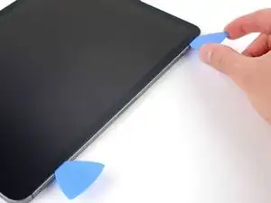
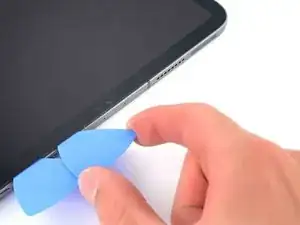
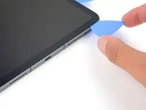
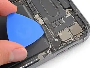
Insert a new opening pick in the bottom right corner below the existing pick.
-
Slide the pick around the bottom right corner to separate the adhesive.
-
-
-
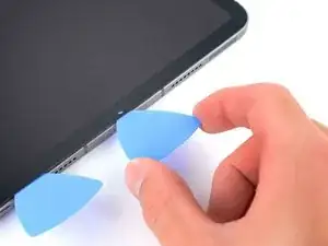
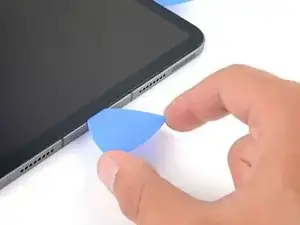
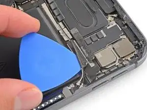
Slide the opening pick along the bottom edge, stopping at the USB-C port.
-
Leave the pick in to prevent the bottom edge adhesive from re-sealing.
-
-
-
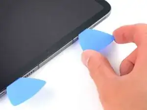
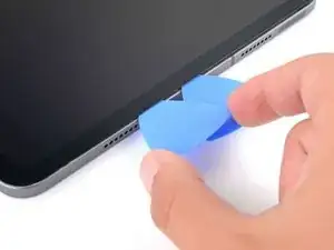
Insert a new opening pick to the left of the USB-C port.
-
Separate the remaining bottom edge adhesive.
-
Leave the pick in the bottom left corner to prevent the bottom edge adhesive from re-sealing.
-
-
-
The display cables are located within small indents of the frame and require an opening pick to be inserted at a 45° angle.
-
There are flat sections of the frame which require an opening pick to be inserted horizontally.
-
-
-
Insert an opening pick at a 45˚ angle just above the bottom left corner.
-
Carefully slide the pick along the left edge, stopping when you reach the flat section of the frame.
-
-
-
Lower the opening pick so it is horizontal to the screen.
-
Continue separating the left edge adhesive until you reach the next indented section of the frame.
-
-
-
Separate the remaining adhesive, making sure to follow the instructions exactly as written.
-
Slide the pick at a 45˚ downward angle and don't insert the pick more than 5 mm.
-
Slide the pick horizontally and don't insert the pick more than 5 mm.
-
-
-
Use an opening pick to remove any remaining adhesive keeping the screen stuck to the frame.
-
Grab the top right and bottom left corners of the screen.
-
Slowly slide the screen towards the bottom right corner to separate it from the frame.
-
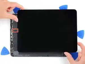
Shift the screen towards the bottom right corner of the frame until the ambient light sensor ribbon cable near the top edge is uncovered.
-
-
-
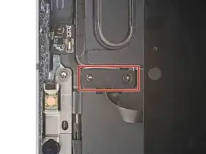
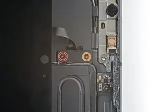
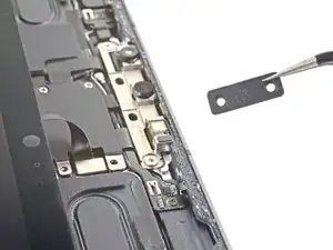
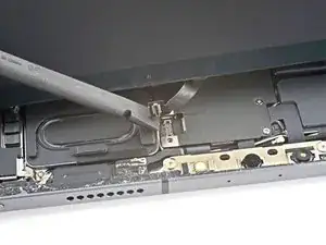
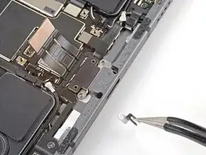
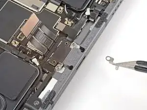
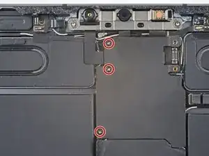
Use a Phillips screwdriver to remove the two screws securing the ambient light sensor cable bracket to the logic board:
-
One 1.3 mm screw
-
One 2.0 mm screw
-
-
-
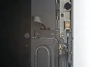
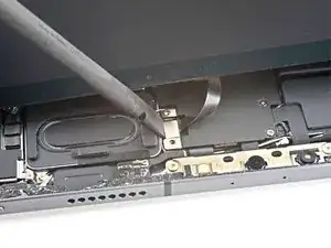
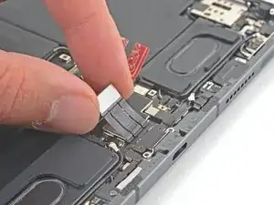
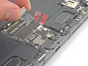
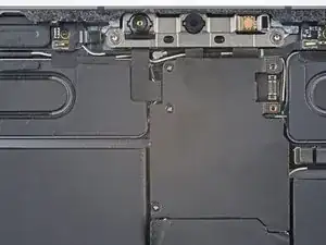
Use the flat end of a spudger to disconnect the ambient light sensor cable by lifting straight up on the press connectors.
-
-
-
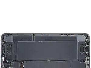
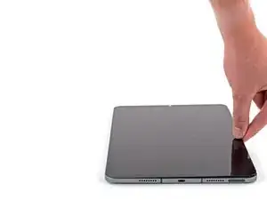
Grip the right edge of the screen and fold it open like a book.
-
Lay the screen down over the left edge of the iPad.
-
-
-
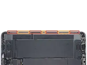
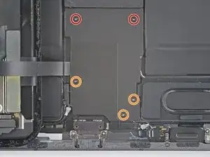
Use a Phillips screwdriver to remove the five screws securing the lower cable shield to the logic board:
-
Two 2.0 mm screws
-
Three 1.3 mm screws
-
-
-
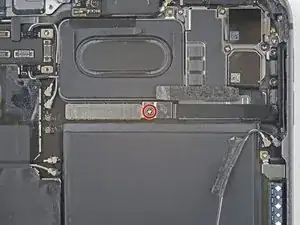
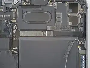
Use a Phillips screwdriver to remove the 1.8 mm screw securing the battery connector to the logic board.
-
-
-
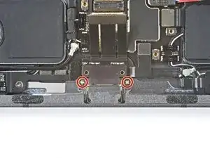
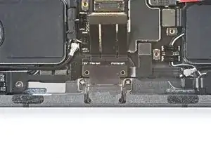
Use a Phillips screwdriver to remove the two 1.9 mm screws securing the USB-C port to the frame.
-
-
-
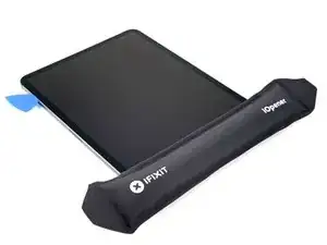
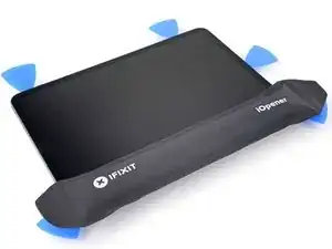
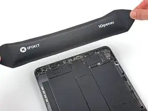
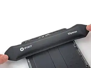
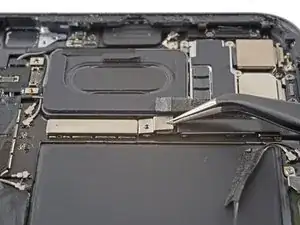
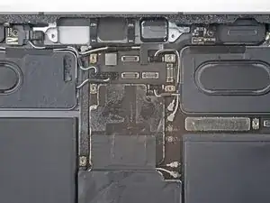
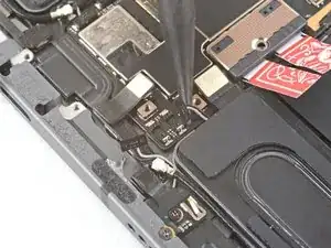
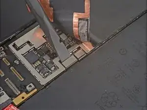
Apply a heated iOpener to the top cable shield for one minute to soften the adhesive securing it to the logic board.
-
-
-
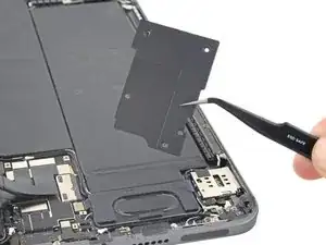
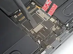
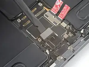
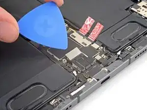
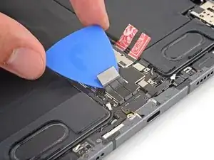
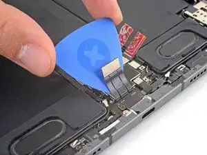
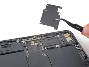
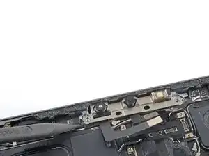
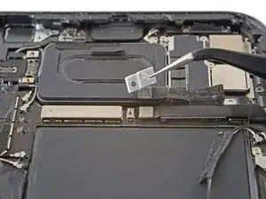
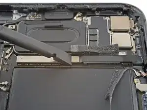
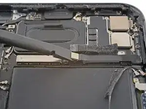
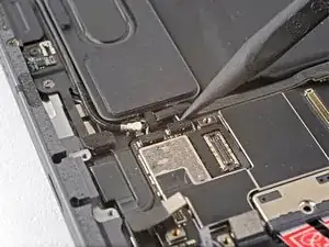
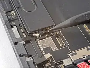
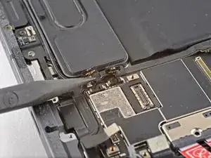
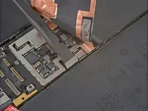
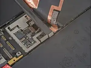
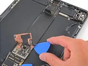
Insert an opening pick under the top cable shield and gently pry up to separate the adhesive.
-
-
-
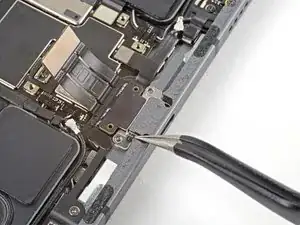
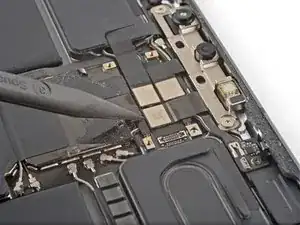
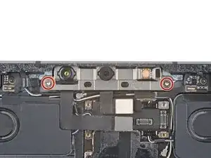
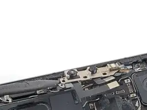
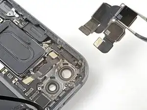
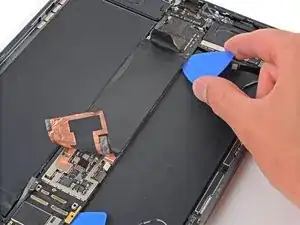
Use a Torx T3 screwdriver to remove the two 2.1 mm screws securing the front camera assembly to the frame.
-
-
-
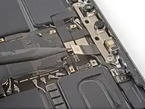
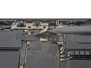
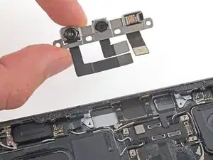
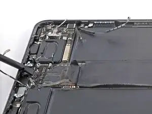
Use the pointed end of a spudger to pry up and loosen the front camera assembly.
-
Use tweezers or your fingers to remove the front camera assembly.
-
-
-
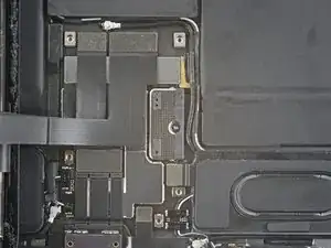
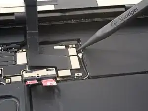
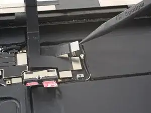
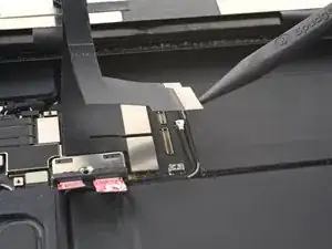
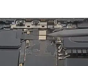
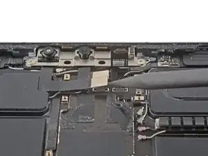
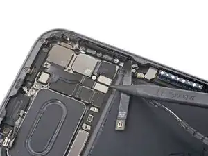
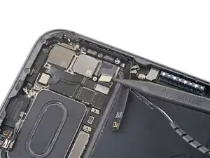
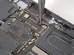
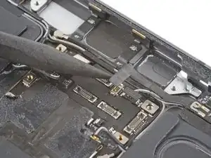
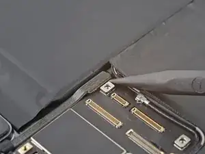
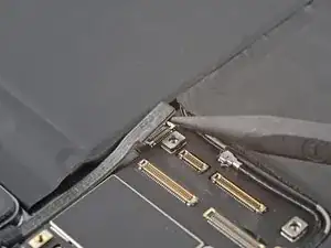
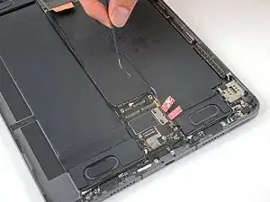
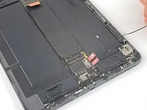
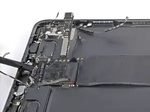
Slide an opening pick between the antenna cables and the mmWave interconnect cable to separate them.
-
-
-
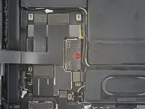
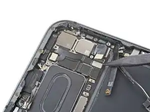
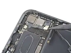
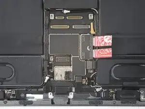
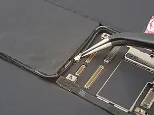
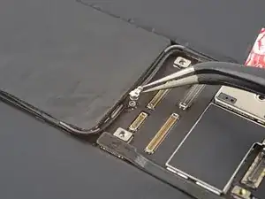
Use a Phillips screwdriver to remove the 1.2 mm screw securing the press connector bracket to the logic board.
-
-
-
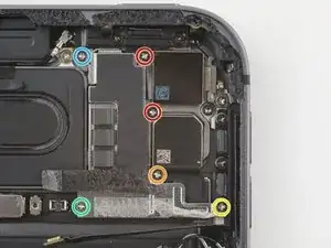
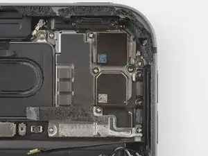
Use your Phillips screwdriver to remove the six screws securing the rear camera shield to the frame:
-
Two 2.8 mm screws
-
One 1.9 mm screw
-
One 1.9 mm screw
-
One 1.2 mm screw
-
One 1.2 mm screw
-
-
-
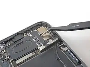
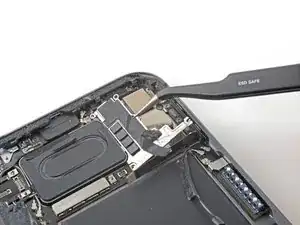
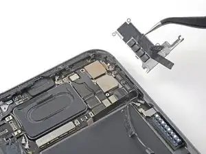
Use tweezers or your fingers to lift the right side of the camera shield up.
-
Slide the shield out horizontally.
-
-
-
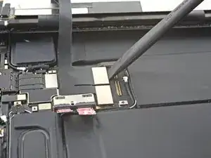
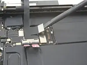
Use the flat end of a spudger to disconnect the LiDAR sensor cable.
-
Fold the LiDAR sensor cable away from the frame to access the press connectors underneath.
-
-
-
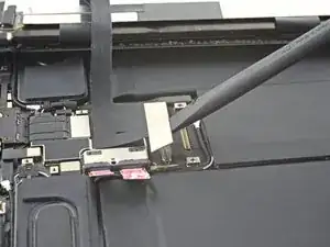
Use the flat end of a spudger to gently pry up and loosen the rear camera module.
-
Use tweezers or your fingers to grab and remove the rear camera module.
-
-
-
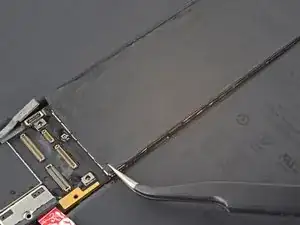
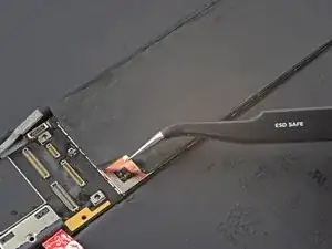
Continue repositioning the antenna cables until they are clear from the bottom of the logic board.
-
-
-
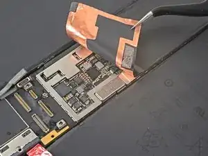
Use tweezers or your fingers to peel back the logic board shielding to reveal the hidden press connectors.
-
-
-
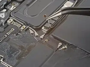
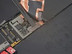
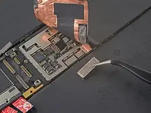
Use the flat end of a spudger to slide out the cable bracket.
-
Use tweezers or your fingers to remove the bracket.
-
-
-
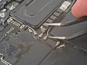
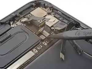
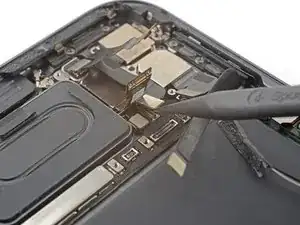
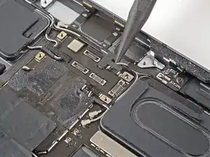
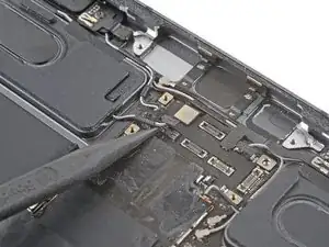
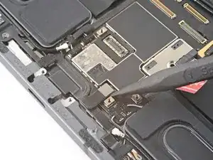
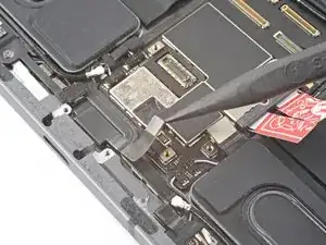
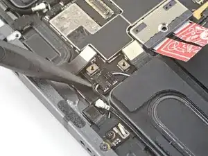
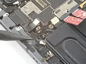
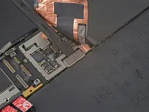
Use the flat end of a spudger to disconnect the left microphone and Apple Pencil charger cables.
-
-
-
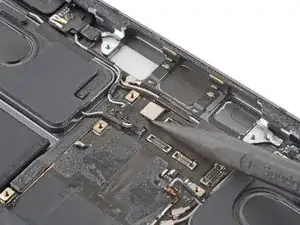
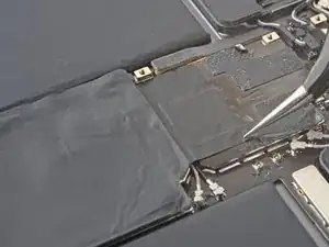
Elevate the left side of the iPad so that it lays down at an angle.
-
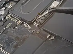
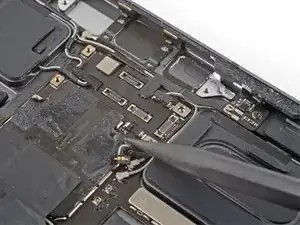
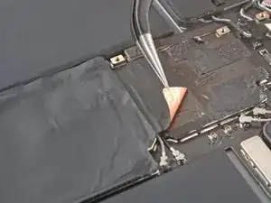
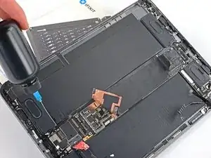
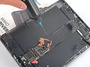
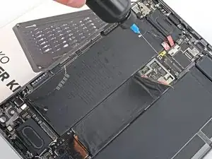
Apply a few drops of isopropyl alcohol along the left edge of the logic board.
-
Let the alcohol soak for one minute to soften the adhesive under the logic board.
-
-
-
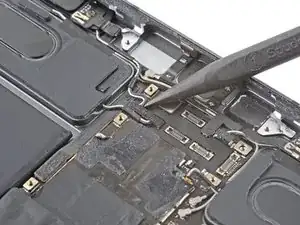
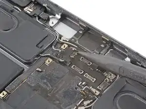
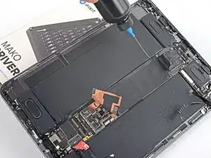
Rotate your iPad 180˚ and lay it down with the right side elevated.
-
Repeat the previous step for the right edge of the logic board.
-
-
-
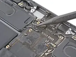
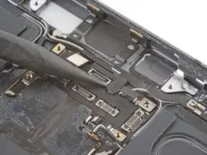
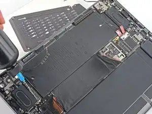
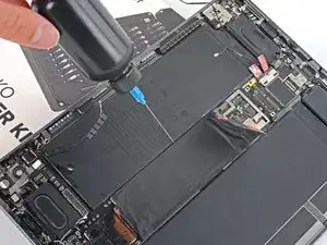
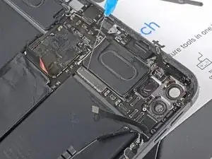
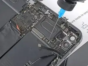
Elevate the top side of the iPad.
-
Apply a few drops of isopropyl alcohol to the right branch of the logic board near the rear camera glass.
-
Let the alcohol soak for one minute to soften the adhesive under the right logic board branch.
-
-
-
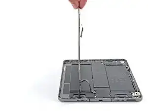
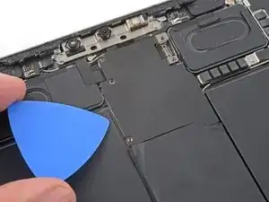
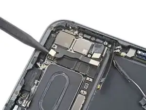
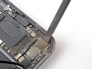
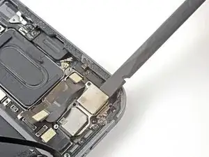
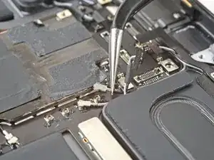
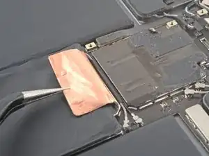
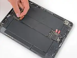
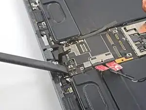
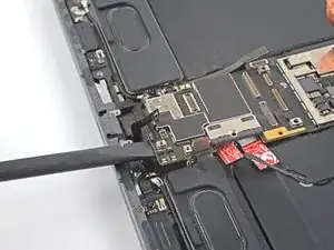
Insert the flat end of a spudger under the lower edge of the logic board.
-
Slowly lift up the bottom of the logic board.
-
Lift up the logic board and replace the playing card battery blocker with an opening pick.
-
-
-
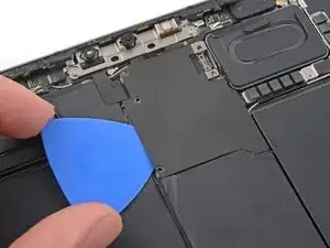
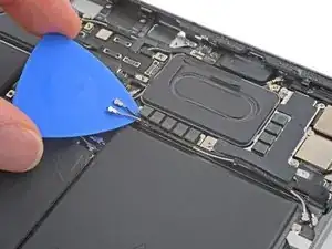
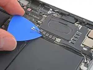
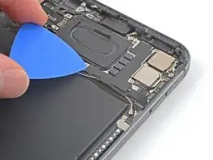
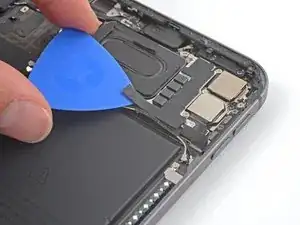
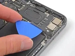
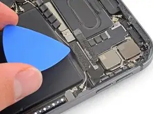
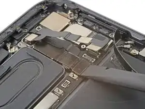
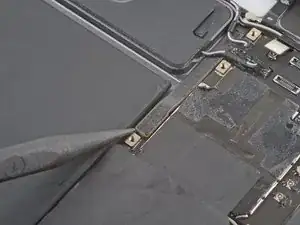
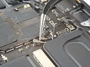
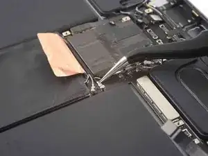
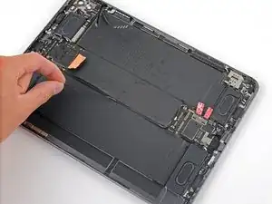
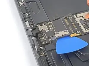
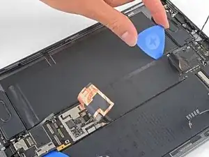
Slide an opening pick under the left edge of the logic board to loosen it.
-
Pry against the frame underneath the logic board to separate the adhesive.
-
-
-
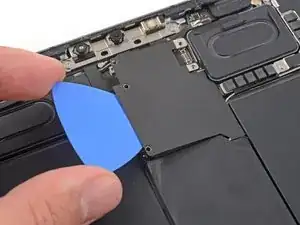
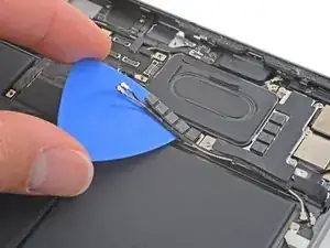
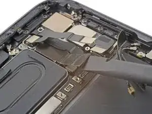
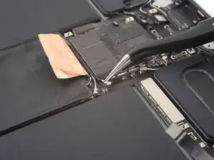
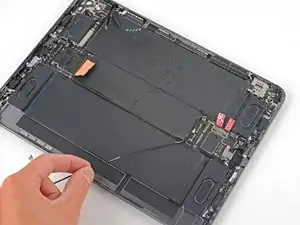
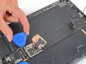
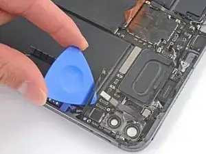
Use an opening pick to gently pry up the top right branch of the logic board near the rear camera lenses.
-
-
-
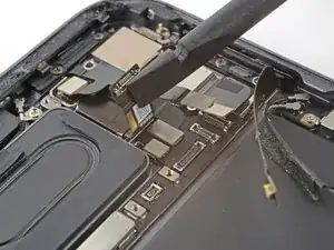
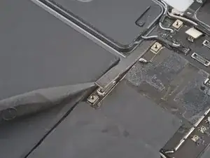
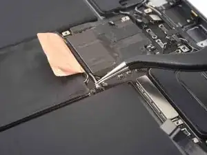
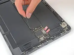
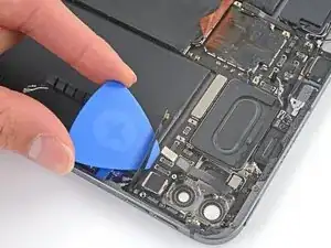
Insert an opening pick under the right edge of the logic board above the left microphone and Apple Pencil charger cables.
-
Slide the opening pick under the right edge of the logic board to loosen it.
-
Pry against the frame underneath the logic board to separate the adhesive.
-
-
-
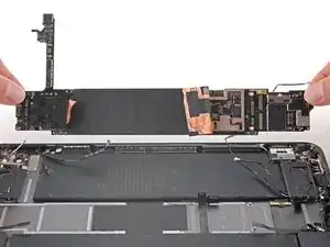
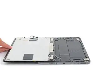
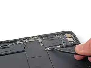
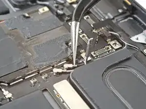
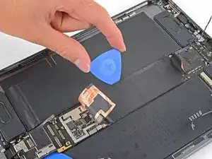
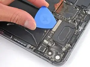
Use the flat end of a spudger to lift the top edge of the logic board.
-
Grip the top and bottom edges of the logic board.
-
Remove the logic board.
-


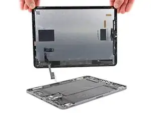

Compare your new replacement part to the original part—you may need to transfer remaining components or remove adhesive backings from the new part before installing.
To reassemble your device, follow these instructions in reverse order.
Take your e-waste to an R2 or e-Stewards certified recycler.
Repair didn’t go as planned? Try some basic troubleshooting, or ask our iPad Pro 11" 3rd Gen Answers community for help.