Introduction
Follow this guide to replace the logic board in your iPad Air 5th Generation.
The Logic Board is paired to the power button. You'll need to transfer the power button with the logic board to keep Touch ID capability.
If your battery is swollen, take appropriate precautions.
Some photos in this guide are from a different model and may contain slight visual discrepancies, but they won't affect the guide procedure.
-
-
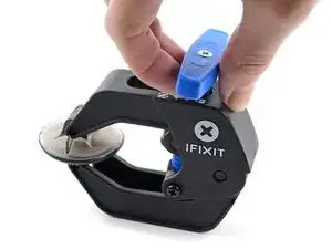
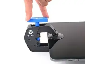
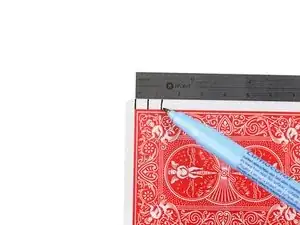
Pull the blue handle backwards to unlock the Anti-Clamp's arms.
-
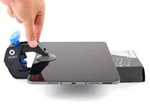
Place an object under your iPad so it rests level between the suction cups.
-
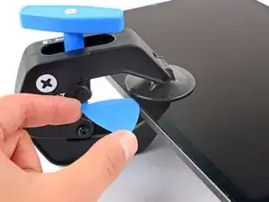
Position the suction cups near the middle of the left edge—one on the top, and one on the bottom.
-
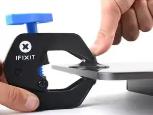
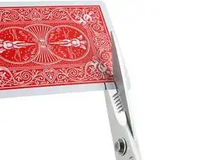
Hold the bottom of the Anti-Clamp steady and firmly press down on the top cup to apply suction.
-
-
-
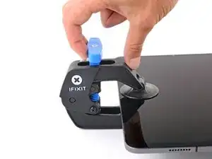
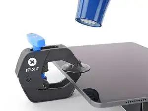
Pull the blue handle forward to lock the arms.
-
Turn the handle clockwise 360 degrees or until the cups start to stretch.
-
Make sure the suction cups remain aligned with each other. If they begin to slip out of alignment, loosen the suction cups slightly and realign the arms.
-
-
-
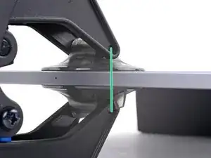
Wait one minute to give the adhesive a chance to release and present an opening gap.
-
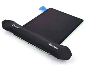
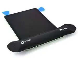
If your screen isn't getting hot enough, you can use a hair dryer to heat along the left edge of the iPad.
-
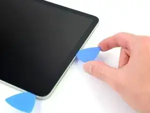
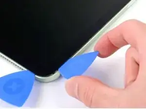
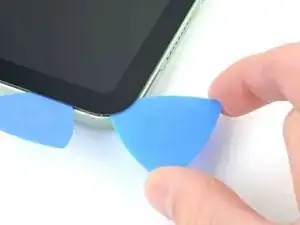
Insert an opening pick under the screen when the Anti-Clamp creates a large enough gap.
-
Skip the next step.
-
-
-
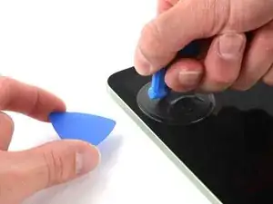
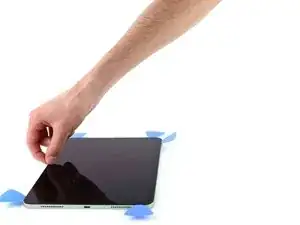
Apply a suction handle to the top left edge of the screen.
-
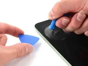
Pull up on the suction handle with firm, constant pressure to create a gap just small enough to insert an opening pick.
-
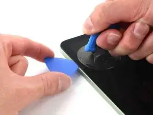
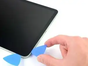
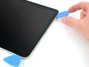
Insert the tip of an opening pick into the gap.
-
Leave the pick in to prevent the adhesive from re-sealing.
-
-
-
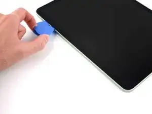
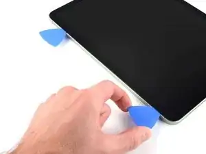
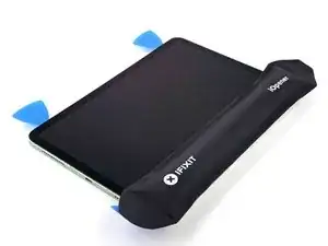
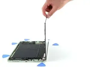
Insert a new opening pick in the gap you just created.
-
Slide the opening pick along the left edge to separate the adhesive.
-
Leave the pick in the bottom left corner to prevent the adhesive from re-sealing.
-
-
-
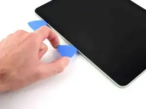
Insert a new opening pick in the bottom left corner.
-
Slide the opening pick along the bottom edge to separate the adhesive.
-
Leave the pick in the bottom right corner to prevent the adhesive from re-sealing.
-
-
-
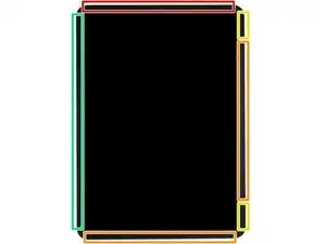
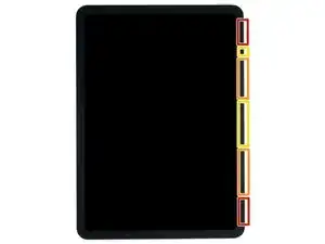
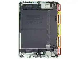
Insert a new opening pick in the bottom right corner and slide along the right edge to separate the adhesive. Make sure to note the following marked areas:
-
Don't insert an opening pick more than 2 mm or you'll damage the screen magnets.
-
Don't insert an opening pick more than 3 mm or you'll damage the display and digitizer cables.
-
Don't insert an opening pick more than 5 mm or you'll damage the display edges.
-
Leave the pick in the top right corner to prevent the adhesive from re-sealing.
-
-
-
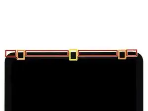
Insert a new opening pick in the top right corner and slide along the top edge to separate the adhesive. Make sure to note the following:
-
Don't insert an opening pick more than 5 mm or you'll damage the display edges.
-
Don't insert an opening pick more than 3 mm or you'll damage the ambient light sensors.
-
Don't insert an opening pick more than 2 mm or you'll damage the front camera module.
-
Leave the pick in the top left corner to prevent the adhesive from re-sealing.
-
-
-
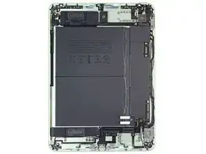
Use a Phillips screwdriver to remove the 1.8 mm screw securing the battery connector to the logic board.
-
-
-
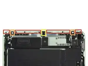
Use a Phillips screwdriver to remove the three screws securing the display and digitizer cable brackets to the logic board:
-
Two 1.1 mm screws
-
One 1.5 mm screw
-
-
-
Use the flat end of a spudger to disconnect the two display cables by lifting straight up on the press connectors.
-
-
-
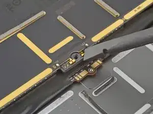
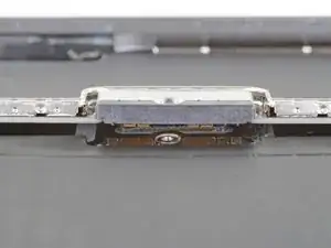
Use a Phillips screwdriver to remove the 1.2 mm screw securing the front camera cable bracket to the frame.
-
-
-
Use the flat end of a spudger to disconnect the two display cables by lifting straight up on the press connectors.
-
Use tweezers to remove the front camera.
-
-
-
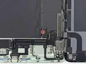
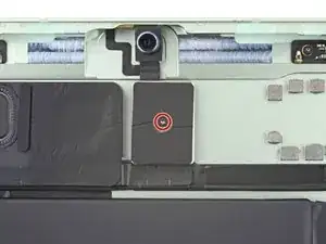
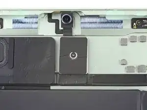
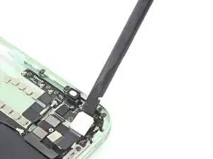
Use a Phillips screwdriver to remove the 1.8 mm screw securing the rear camera cable bracket to the frame.
-
-
-
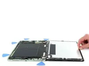
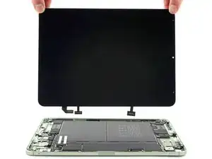
Lay the iPad screen side down.
-
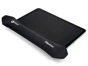
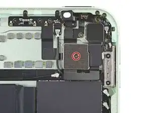
Apply a heated iOpener to the rear camera for two minutes to weaken the adhesive.
-
-
-
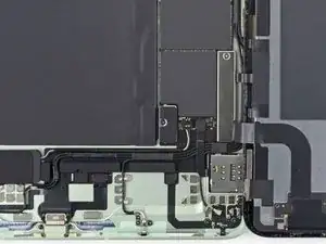
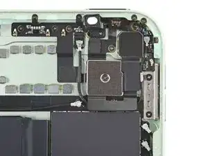
Lay the iPad screen side up.
-
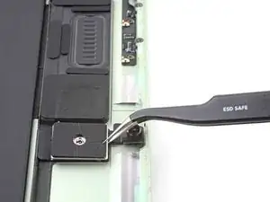
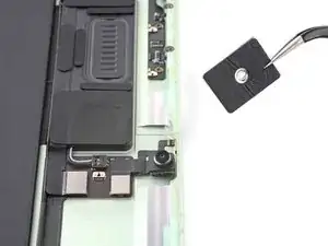
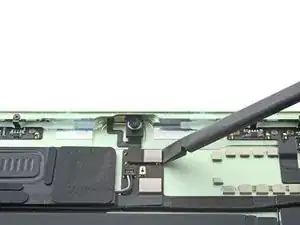
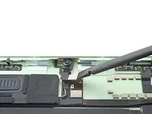
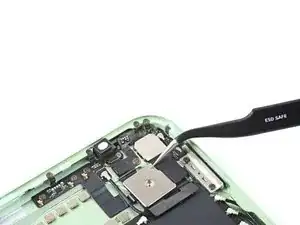
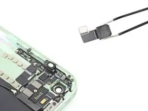
Use the flat end of a spudger to pry up the rear camera.
-
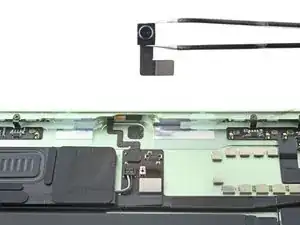
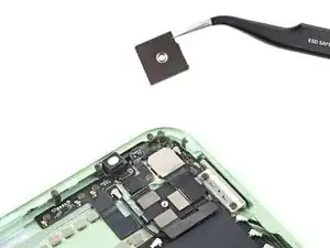
Remove the rear camera.
-
-
-
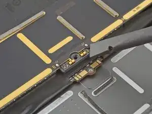
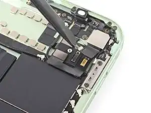
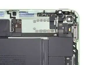
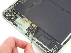
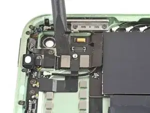
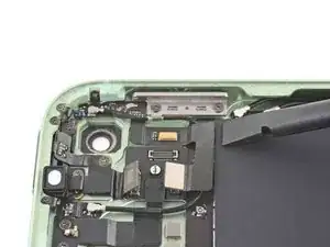
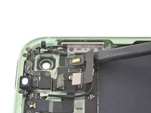
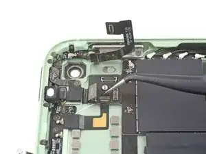
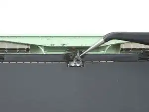
Use tweezers or a spudger to lift up the latch on the ZIF connector.
-
Use tweezers to pull the top microphone cable out of its socket.
-
-
-
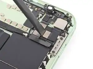
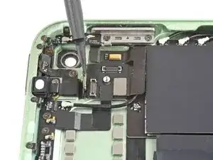
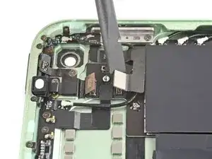
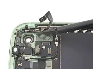
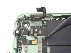
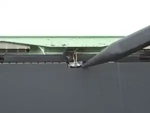
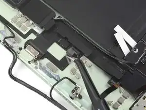
Use the pointed end of a spudger to disconnect the top speaker cable by prying straight up on the rear of the connector.
-
-
-
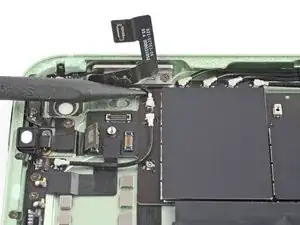
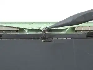
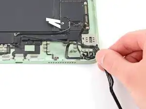
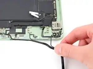
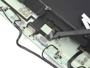
Use tweezers or your fingers to peel the top left Wi-Fi antenna cable off of the top interconnect cable.
-
-
-
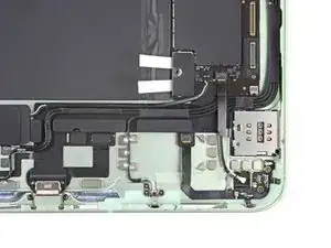
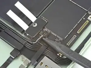
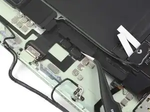
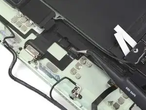
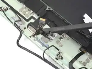
Insert the flat end of a spudger under the volume button and rear microphone cable.
-
Bend the cable to the right so the two Wi-Fi and cellular antenna cables underneath are accessible.
-
-
-
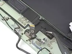
Use the pointed end of a spudger to disconnect the top right antenna cable.
-
Peel the tape away while removing the cable.
-
-
-
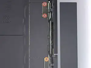
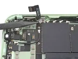
Disconnect the top right antenna interconnect cable:
-
Peel off the tape
-
Flip up the latch
-
Pull out the cable
-
-
-
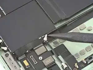
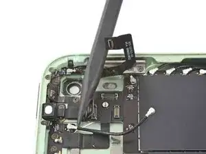
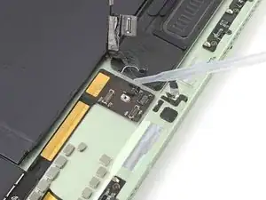
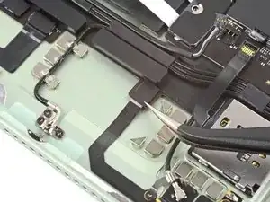
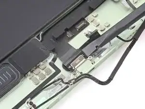
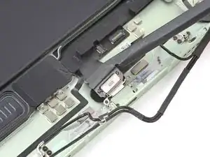
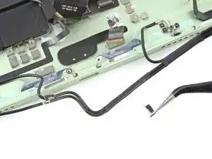
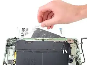
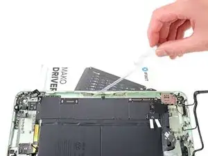
Apply a few drops of high-strength (>90%) isopropyl alcohol along the edges of the top interconnect flex cable.
-
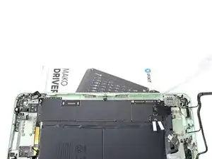
Let the alcohol soak for one minute to soften the adhesive under the cable.
-
-
-
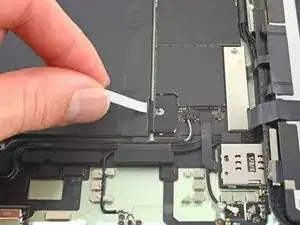
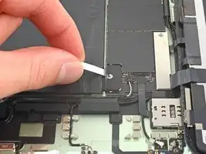
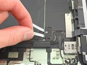
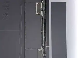
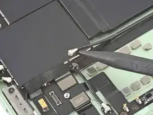
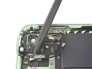
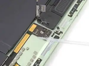
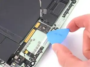
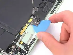
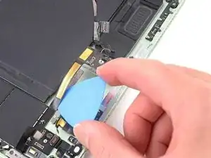
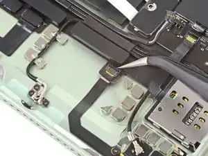
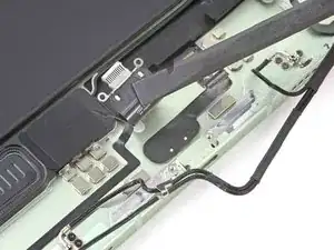
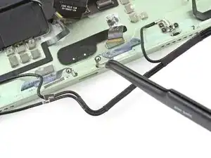
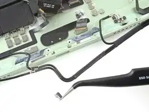
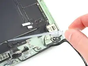
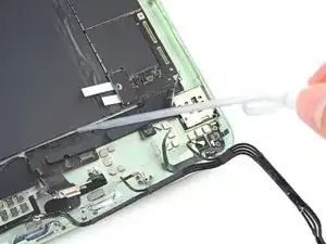
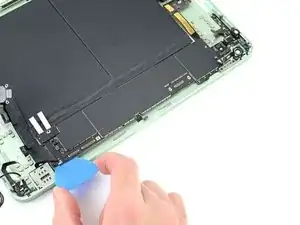
Insert an opening pick under the interconnect flex cable.
-
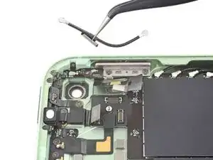
Slide the pick under the cable towards the logic board to separate the adhesive.
-
-
-
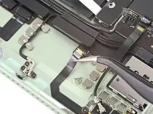
Use the pointed end of a spudger to disconnect the four antenna cables below the volume buttons.
-
-
-
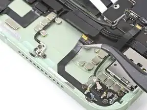
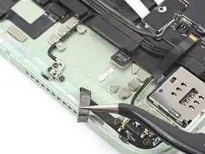
Use the pointed end of a spudger to disconnect the bottom speaker cable by prying straight up on the rear of the connector.
-
-
-
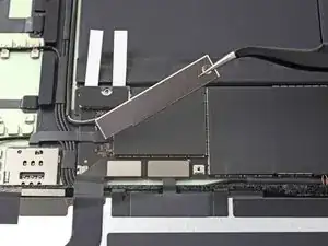
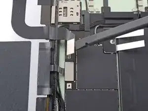
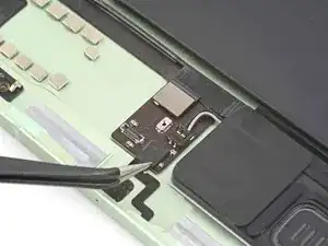
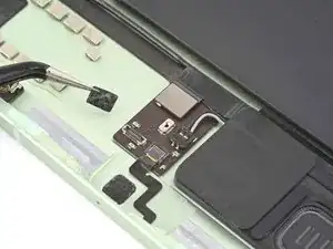
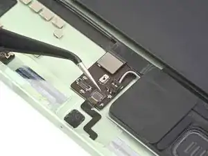
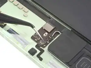
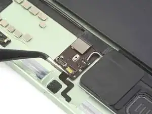
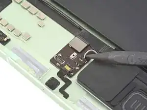
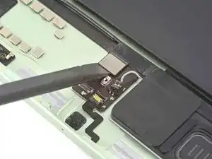
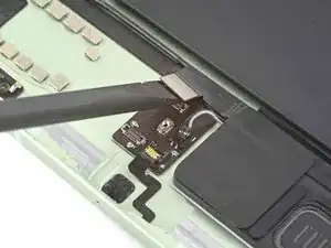
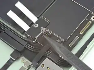
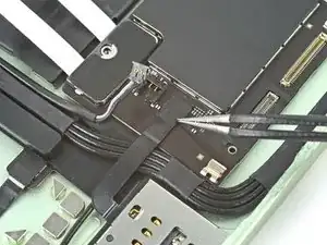
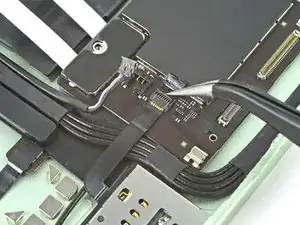
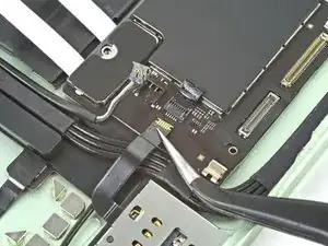
Disconnect the SIM card reader cable:
-
Peel off the tape
-
Flip up the latch
-
Pull out the cable
-
-
-
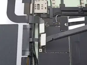
Disconnect the bottom right antenna interconnect cable:
-
Peel off the tape
-
Flip up the latch
-
Pull out the cable
-
-
-
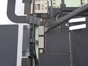
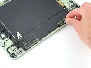
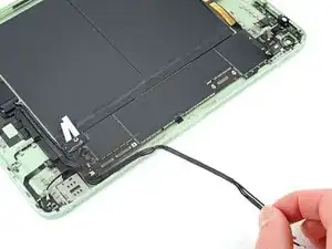
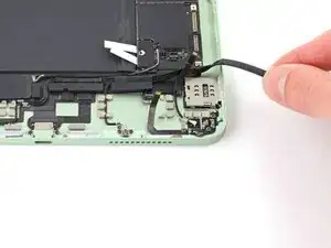
Use your fingers to lift and unroute the antenna cable harness away from the right edge of the iPad.
-
-
-
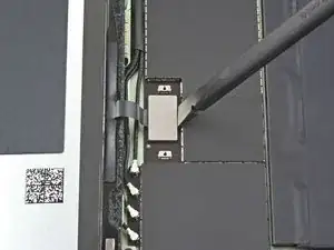
Disconnect the Smart Connector cable:
-
Peel off the tape
-
Flip up the latch
-
Pull out the cable
-
-
-
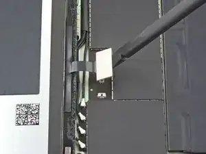
Insert the flat end of a spudger under the Smart Connector cable.
-
Slide the flat end of a spudger under the cable to separate it from the frame.
-
-
-
Repeat the previous step to disconnect and separate the lower left antenna interconnect cable.
-
-
-
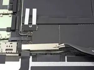
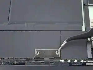
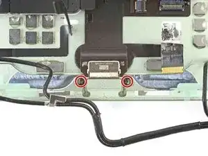
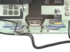
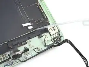
Use a Phillips screwdriver to remove the two 2 mm screws securing the USB-C port to the frame.
-
-
-
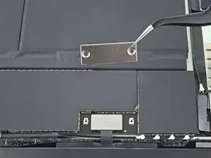
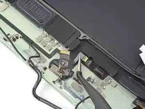
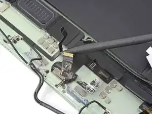
Insert a spudger under the USB-C port cable.
-
Lift the USB-C port out of its slot in the frame.
-
-
-
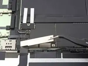
Prop the top side of the iPad up so the isopropyl alcohol can flow under the USB-C port cable.
-
Apply a few drops of high-strength (>90%) isopropyl alcohol along the top edge of the USB-C port cable.
-
Let the alcohol soak for one minute to soften the adhesive under the cable.
-
-
-
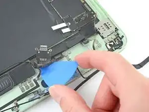
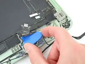
Insert an opening pick under the USB-C port flex cable.
-
Slide the pick along the cable towards the logic board to separate the adhesive.
-
-
-
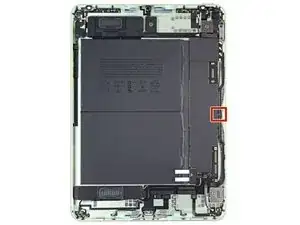
Prop the right side of the iPad up so the isopropyl alcohol can flow under the logic board.
-
Apply a few drops of high-strength (>90%) isopropyl alcohol along the right edge of the logic board.
-
Let the alcohol soak for one minute to soften the adhesive under the logic board.
-
-
-
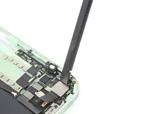
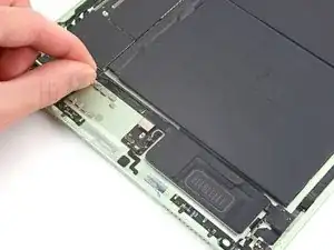
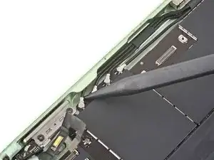
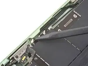
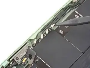
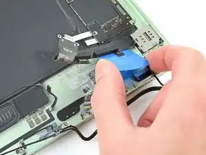
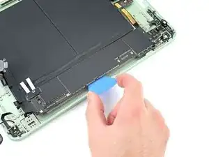
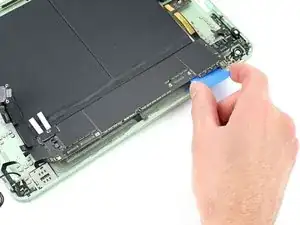
Insert an opening pick under the right edge of the logic board.
-
Pry up and slide along the right edge of the logic board to separate the adhesive securing it to the frame.
-
-
-
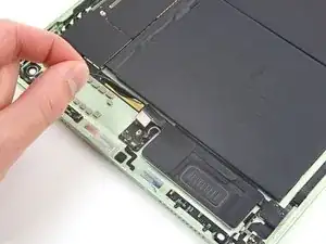
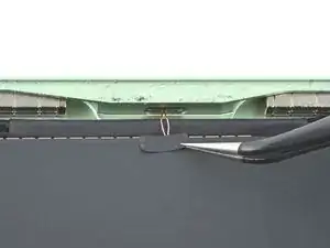
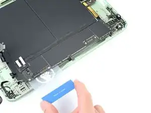
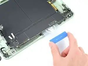
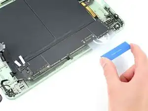
Insert a plastic card under the right edge of the logic board.
-
Pry up and slide along the right edge of the logic board to separate any remaining adhesive.
-


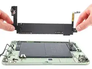
To reassemble your device, follow these instructions in reverse order.
Take your e-waste to an R2 or e-Stewards certified recycler.
Repair didn’t go as planned? Try some basic troubleshooting, or ask our iPad Air 5th Generation answers community for help.