Introduction

Follow this guide to remove or replace the logic board in a Wi-Fi only iPad Air 3. The cellular model will require disconnecting the upper cellular antennas.

For your safety, discharge the battery below 25% before disassembling your iPad. This reduces the risk of a dangerous thermal event if the battery is accidentally damaged during the repair. If your battery is swollen, take appropriate precautions.

The logic board is paired to the Touch ID fingerprint sensor. If you replace the logic board, your Touch ID sensor will no longer work as a fingerprint sensor. It will still work as a home button.

Some photos in this guide are from a different model and may contain slight visual discrepancies, but they won't affect the guide procedure.

  1. otaRXAqJBHRfjpZL
    • Strong adhesive holds the screen in place. In order to separate it, you'll first need to heat and soften the adhesive using an iOpener, hair dryer, or heat gun.

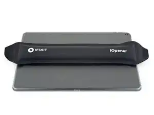
    • You may need to reapply heat repeatedly throughout this process to prevent the adhesive from cooling and hardening.

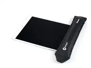
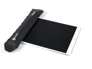
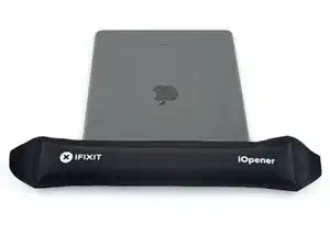
    • Prepare an iOpener and place it on the bottom edge of the iPad's screen for about two minutes.

  2. dXwytgcbeMBtyPIK
    • If your iPad's screen is badly cracked, wear skin and eye protection. Cover the screen with a smooth layer of clear packing tape to contain glass shards and help the suction cup adhere. Alternatively, use a strong piece of tape (such as duct tape) and fold it into a handle.

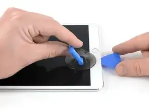
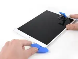
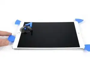
    • Place a suction cup next to the iPad's home button and press down to create a seal.

    • To get the most leverage, place the suction cup as close to the edge as possible without going past the edge of the display.

    • If you want to use the Anti-Clamp, a tool we designed to make the opening procedure easier, follow this guide.

    • Firmly pull up on the suction cup to create a small gap between the front panel and the rear case.

    • Don't pull too hard, or you may shatter the glass. If necessary, apply more heat to further soften the adhesive.

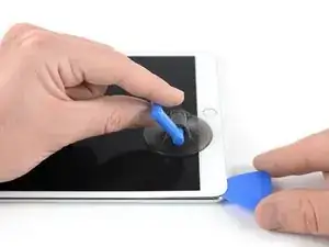
    • Once you've opened a sufficient gap, insert an opening pick into the gap.

    i used a proper suction tile puller (small one from DIY store used to hold bathroom tiles) to lift the screen off after heating around the edge using a heat gun. Be careful - It didn't damage anything. The tiny suction things that come with those iPhone kits are not strong enough for this. The one in picture might be good, but looks similar to the kits ones that have key ring.

    Robert Lord -

    The suction cup that comes with the iPad battery replacement is plenty large enough and strong enough.

    CAUTION, do not push the picks in more than a the width of the replacement screen adhesive strips. You will damage the $200 screen, maybe break the glass. The screen is multiple layers and the picks can get in-between the layers if you push too far in. I got into trouble at the lower left corner. After getting the screen loose, I found that I only need a 2-3 millimeters on the sides and bottom, and four or five millimeters in the corners.

    Gene Torrey -

  3. HRYjnydwI5uHt12k
    HRYjnydwI5uHt12k
    2nxd5mrkce3UfC1r
    • Slice through the adhesive under the screen by sliding the pick along the edge of the display, towards the bottom left corner.

    • Leave the pick in place temporarily to prevent the adhesive from re-sealing.

    Be super carful at the sides! If you insert your pick more than ~2mm, you will separate your display and front glass.

    voidfish -

  4. IDX6WsfJwQGPK1hD
    IDX6WsfJwQGPK1hD
    woVkXQtjng5taXfv
    CX5pQLbDVpljSlel
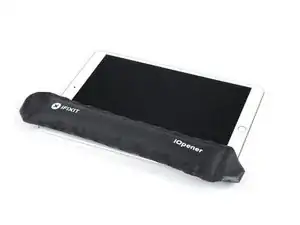
    • Apply heat to the left edge of the iPad for about two minutes, or until it's slightly too hot to touch comfortably.

    • If necessary, re-heat your iOpener for a few seconds or until it's a bit too hot to touch. Be careful not to overheat the iOpener, or it may burst.

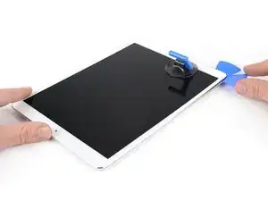
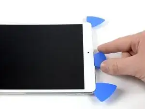
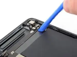
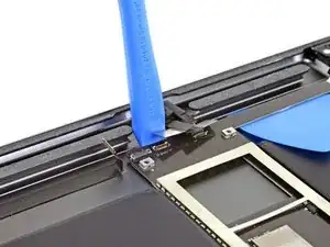
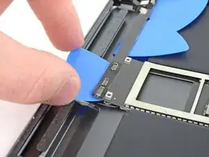
    • Insert a second opening pick at the bottom left corner of the iPad.

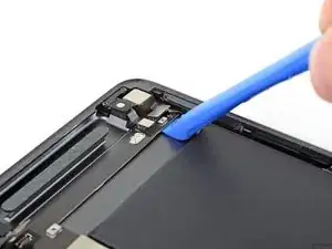
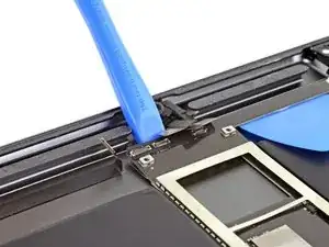
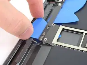
    • Slide the second opening pick along the left side of the display to separate the adhesive underneath.

    • Leave the opening pick inserted near the top left corner of the iPad to prevent the adhesive from re-sealing.

  5. Xsv3FIGGDpg2cySF
    • Apply heat to the top edge of the iPad for about two minutes, or until it's slightly too hot to touch comfortably.

  6. iaIrQdhTPk3NQkBo
    iaIrQdhTPk3NQkBo
    5MDrFiJpRxgYtktW
    rZvTbO5Akf3ef1fF
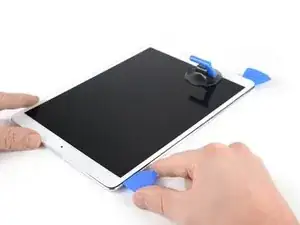
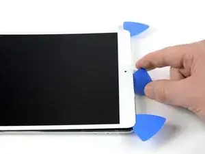
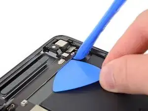
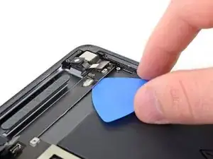
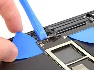
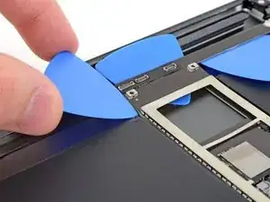
    • Insert a third opening pick at the top left corner of the iPad.

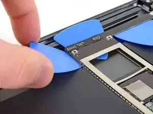
    • Use the opening pick to cut the adhesive under the top edge of the iPad by sliding it to the top right corner.

    • The front-facing camera is located right in the center of the iPad's top edge and can be damaged if the pick is inserted too far. Only insert the tip of the opening pick when cutting near the camera.

  7. NcHeiicA1BxMtSMG
    NcHeiicA1BxMtSMG
    2nq2lKnxklD4SEqb
    FyR4ypp5WTIbhUo3
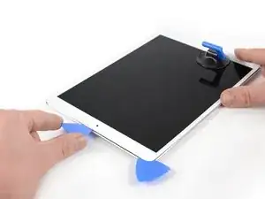
    • Apply heat to the final, right edge of the iPad for about two minutes, or until it's slightly too hot to touch comfortably.

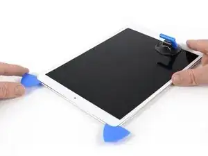
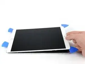
    • Insert a fourth opening pick at the top right corner of the iPad.

    • Slide the opening pick down to the bottom right corner to cut the adhesive.

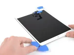
    • Slide the opening pick around the bottom right corner—pausing to apply more heat if needed—and cut the remaining adhesive on the bottom edge, but stop before you reach the home button.

    We must be very careful when we are prying left and right size bezel to peel off the screen as there very little gap between edges and LCD. Slightly inside push can crack LCD. We need to pay full care and raising edges very very slowly.

    iRepairMan -

  8. yNLpdqy3o1k2mXRL
    yNLpdqy3o1k2mXRL
    IGBVYHPJbbyL5okD
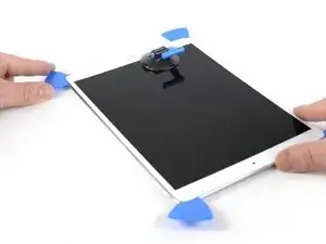
    • Insert a fifth opening pick at the top of the iPad near (but not directly on) the front-facing camera.

    • Gently twist the pick to separate the display assembly from the iPad.

    • Don't try to remove the display all the way yet! It is still connected to the iPad's motherboard.

    • If needed, apply more heat and/or cut any remaining adhesive that prevents the display from separating.

    Be very gentle when twisting. My screen broke in this step. I would not twist it but try to remove glue further as there is a aluminium support of the screen in the wide area beneath the light sensors and there is glue on that also preventing in easy lifting the screen. Just be careful not to damage the light sensors and camera.

    agrior -

  9. ocbIAZjbSbxccEWF
    ocbIAZjbSbxccEWF
    ZXh6TyUUb4CQX1wM
    ExGEFNSRgrxMVNIy
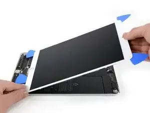
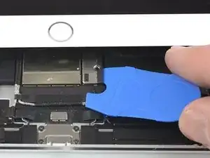
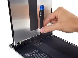
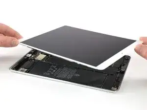
    • Lift the display assembly from its top edge and carefully slide it up (towards the front-facing camera and headphone jack), until the screw that secures the battery power connector is revealed at the bottom.

    • Don't lift the display more than 70° or you may damage the attached ribbon cables.

    How do you go about getting to this battery connector as it is covered by a large metal shield above the logic board, if you do not disconnect the battery you risk frying the back light.

    Ayden McCormack -

    The metal shield is not relevant for this. You can leave it in place or remove it if it comes of. Once the screw of the plate is removed you will be able to lift the print a little bit and put someting between the battery connector and the board connector. The connector is beneath the print. Look further on to see a deck card is used for this.

    agrior -

  10. 4rXEwLDSrwuJsswL
    4rXEwLDSrwuJsswL
    neY1rxtpUctU1N3T
    • Remove the 1.9 mm Phillips screw that secures the battery power connector.

    • Throughout this repair, keep track of each screw and make sure it goes back exactly where it came from to avoid damaging your device.

    What size Phillips bit?

    Josh Heilik -

    In this whole guide I used 00 and 000.

    agrior -

  11. 4ouBh4GC2IOhyKNR
    4ouBh4GC2IOhyKNR
    5VpvOTBpSOqCXNgw
    PsWasEsoNUIanBMK
    • These photos show what the battery connector looks like underneath the logic board. Use these photos as a reference while you safely disconnect the battery.

    • Notice that the battery connector has cantilever springs on the logic board that press against the battery contact pads. Since both the logic board and battery are glued down, you'll need to slide something thin and flexible between the contact points to disconnect the battery.

    This picture looks nothing like my A2152 battery connector. I can’t really tell what is happening here.

    todd sorel -

  12. 2e3jiUVhPCTeK3V2
    • Be careful when you isolate the battery using a battery blocker. The battery contacts are easily bent or broken, resulting in irreversible damage.

    • To disconnect the battery, slide one prong of a battery blocker or the tip of an opening pick under the battery power connector to ensure the power circuit is interrupted.

    • Don't push the battery blocker underneath the connector with excessive force. If you're having trouble fitting the battery blocker underneath the logic board, you can try using a playing card to disconnect the battery instead.

    • The battery blocker or playing card ideally should slide under the logic board without encountering any blockages.

    • Leave the battery blocker in place as you work.

    I found it very hard to fit something under the battery power connector. I did not have a battery blocker, so I tried a playing card. I was not able to slide it between the springs. The section of the battery power connector, above the cantilever springs, did not seem to want to give at all, like in the picture above. If other people had success, I would love to hear how.

    hdh607 -

    I didn’t have success either, but i kept myself grounded, and avoided battery contact as much as possible.

    Amber Wooldridge -

    I used a playing card cut to shape. I had to make a couple, to try a few times.. It does go in eventually. Not deep, but enough to break connection. You can test by trying to switch on iPad.

    Robert Lord -

    It took some time but I was able to get it under the back part and slide it forward.

    Barbara Nelson -

    You must disconnect the battery before plugging the new screen. I think i didn't break the circuit in first attempt and shorted the screen, the result was half of the screen didn't work. I used a playing card. Second attempt was successful with new screen.

    Robert Lord -

    I believe I have a good solution to this problem. I was dissatisfied with the thickness of the battery blocker, or even a thin guitar pick, for that matter; both required force and I feared bending the springs or leaving the connection intact.

    What worked for me was cutting a small strip of non-conductive, static-proof film (the kind that RAM and other sensitive components come in). There was every reason to trust in its non-conductivity but just to be sure, I used a VOM to test; its resistance was out of the VOMs range, meaning that its conductivity was nil. I used a spudger to gently lift the logic board off of the battery contacts and slid the non-conductive strip in between; went without a hitch.

    When reassembling, I laid the strip on the battery contacts, laid the logic board on top, installed it, connected the display panel and gently drew the slip out and installed the battery screw. Worked like a charm.

    Valdaquende -

    These are some extremely misleading set of instructions and picture. Much better if you have the battery discharged, so don't need to worry about blocking the connector. But DO NOT force anything in the through the socket and certainly do not try to bend up the soldered cover, as it appears to be happening in the picture. You will break the connector, most likely resulting in ipad shutting down every 3 minutes from the notorious "thermal sensor missing" panic system crash.

    Kostas “Kosprey” -

  13. vuHXR5SLK1ppwfYQ
    vuHXR5SLK1ppwfYQ
    rohBSEFOJRJTRUcZ
    lPR1DjbIaXn1OdBK
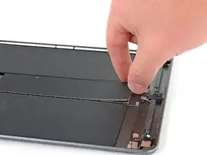
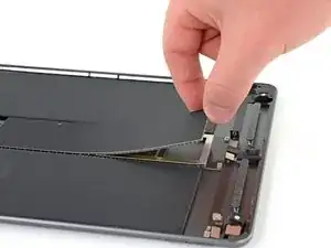
    • Slowly lift the display from its top edge, being careful not to strain the attached ribbon cables.

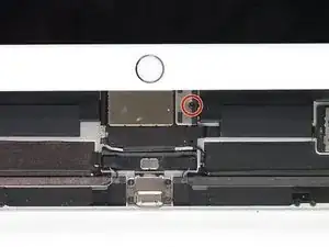
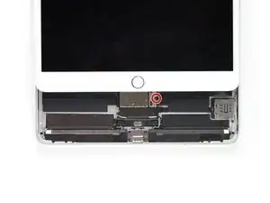
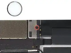
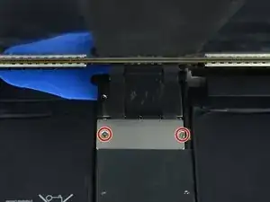
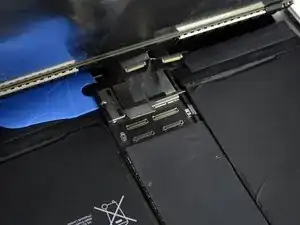
    • Remove the two 1.3 mm Phillips screws securing the display connector cover bracket.

    • You may need to angle the driver slightly in order to avoid straining the ribbon cables.

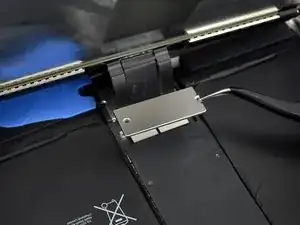
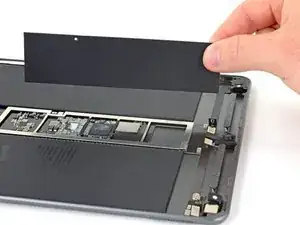
    • Remove the display connector cover bracket.

    Here it is very precocious steps to do. Flx cables to connectors are small in size and we cannot lift the display vertically. Therefore, we may struggle to unscrew the metal shield. We need to use smaller size of philip screw driver or place vertically the display to create enough gap between philip screw driver and the cover bracket. Similarly, when we are replacing new display we need to be carefully connect four flex cable with connectors with logic board.

    iRepairMan -

    agree, with re-assembly very tiny screws and awkward positioning, the back two cables pop off if not careful.

    Tom McGrath -

    I did this step using just the tip of the PH000 screwdriver, it made it much easier to get my hands into the small space, the replacement screen from ifixit had tighter cables that I was not comfortable stretching out to go to a 90* angle to screw back on. Make sure your tip is magnetized for best results :)!

    Amber Wooldridge -

    Meaning no disrespect for this excellent guide, I found this photo to be a bit misleading; at least in my case. It clearly shows about 90˚ between the case and the display. I tested the limits with the one I was repairing and could find no way to raise the display far enough to clear a screwdriver without jeopardizing the cables. I resorted to the same solution that Amber Wooldridge discovered; using a PH000 bit and hand-tightening. I had a tiny needle-nosed plier that I used to tighten them a bit (but very gently).

    Valdaquende -

  14. eFMfF6wqyCeBKRSU
    eFMfF6wqyCeBKRSU
    AQUlSPXnIfQFunMv
    quIQSO3BZ4g5PHqS
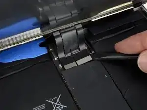
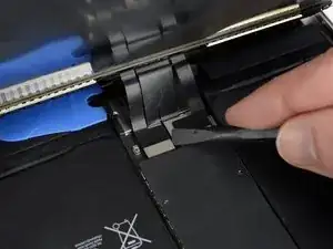
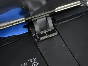
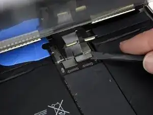
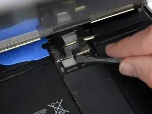
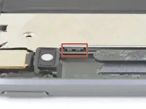
    • Use a spudger to disconnect the two visible display flex connectors by gently prying them straight up from their sockets.

    • To re-attach press connectors like this one, carefully align and press down on one side until it clicks into place, then repeat on the other side. Do not press down on the middle. If the connector is misaligned, the pins can bend, causing permanent damage.

  15. rLEFxLicwMOpGHhK
    rLEFxLicwMOpGHhK
    TAwItumI5lUCWasR
    FBQrmOyUp3ST3UwV
    • Underneath, you'll find two additional display cable connectors.

    • Use your spudger to gently pry them up and disconnect them.

    I went to replace the LCD assembly on an ipad Air 3, and one of the flex cables on the new LCD assembly broke in half. The flex cables on the old assembly work well and are intact. Is it possible to transfer the old flex cable(s) to the new assembly, or can I solder the broken pieces of the new flex cable together? I have also contacted the part supplier about this and am awaiting a response.

    Krella -

  16. kYoe4hwvKgs3PFDe
    • Remove the display assembly.

    • During reassembly, before installing a display, remove any remaining adhesive from the iPad, and clean the glued areas with high concentration isopropyl alcohol (90% or greater) and a lint-free cloth. This helps prep the iPad for fresh adhesive and ensures that it will bond properly.

    • If you plan to reinstall your existing display, remove any remaining adhesive from the back and clean the adhered areas with isopropyl alcohol.

    • Test your iPad's functions and install pre-cut adhesive strips to the back of the display using our display adhesive application guide before sealing it up.

    Definitely test your iPad’s functions before sealing it up. I needed to reopen the display to reconnect the display connectors in order to have the display functioning properly. As a result, the adhesive strips did not work as well and I needed to tape some of the edges closed with a small section of strong clear packing tape.

    hdh607 -

    I stuck the adhesive to the chassis first. That was messy because the plastic that covers the adhesive seems to be for screen side first. So you end up exposing both sides and those collect dust. I now realise you're supposed to put the adhesive on screen first. Not sure if it would have made much difference in the outcome (mine screen is not stuck in some places).

    Robert Lord -

    I found this out too. I had two sealing kits and they were both meant to be fixed on the screen first. I did not managed to get the screen to stick with the body as well. Now used some B6000 glue in addition.

    agrior -

  17. 61FSTJYwKBNeoiIs
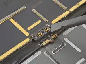
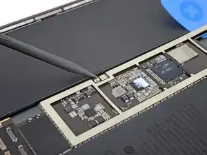
    • Use a Phillips screwdriver to remove the five screws securing the upper component bracket:

    • Three 1.4 mm-long screws

    • Two 2.4 mm-long screws

    On the LTE version, there are four more additional screws at top edge to the left and right of the front facing camera, right below the antenna assemblies.

    Gregg Stanley -

  18. H1LqAwdT61uSGC5Z
    H1LqAwdT61uSGC5Z
    TxPgFPs4Ib2JRkQv
    sumOlypQKDFOCT43
    • Use a spudger to push the upper component bracket towards the upper edge and off of the clips located near the rear camera.

  19. 36iJuRRuHNeAhTyF
    36iJuRRuHNeAhTyF
    NSD5aPKQofpAXrLr
    • Remove the upper component bracket.

    • During reassembly, make sure that the upper component bracket slides under the clips near the rear camera.

  20. CcfFBMMX6WrRNsXG
    CcfFBMMX6WrRNsXG
    BBJXOqWXDKD1HsJw
    K1ja32vpNTHHgn3U
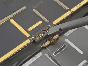
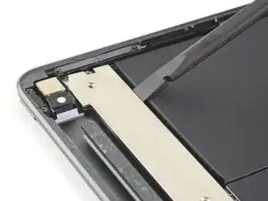
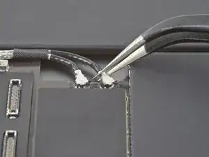
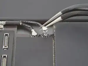
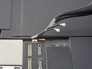
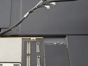
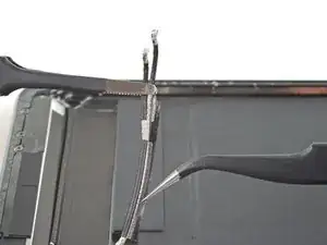
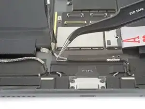
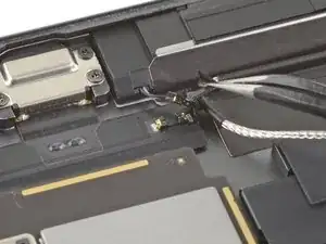
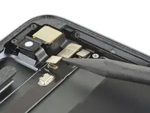
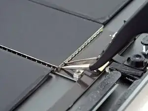
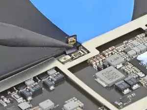
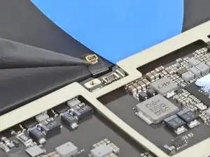
    • Use a pair of tweezers to disconnect a logic board antenna cable by lifting up on the cable as close to the connector as possible.

    • Take care not to puncture or bend the battery with your tool—a punctured or bent battery may leak dangerous chemicals or cause a thermal event.

    • Repeat for the other logic board antenna cable.

  21. Ep2LrjwmulPjBDMm
    Ep2LrjwmulPjBDMm
    qCbTsB4TNlW1hFXr
    nkcDRaLvY3yP5HV5
    • Use a pair of tweezers to lift the antenna cables away from the logic board.

  22. csLjS2uKMWE1nyPm
    csLjS2uKMWE1nyPm
    ZWeF4XAsA2GFUCQW
    LeeFmXTStLXdQ6HF
    • Use a pair of tweezers to unwrap the tape securing the two antenna cables together.

    You don't need to unwrap the tape; you can use tweezers and separate the tape from the logic board and GNETLY lift the whole assembly above the bottom of the logic board.

    Gregg Stanley -

  23. n3ZFNj2u42fvub6f
    n3ZFNj2u42fvub6f
    RPyfUXcnXiXOHihl
    RjaRYXX54CWLFUaj
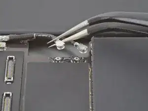
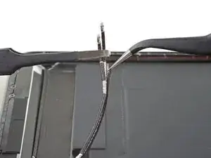
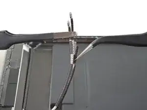
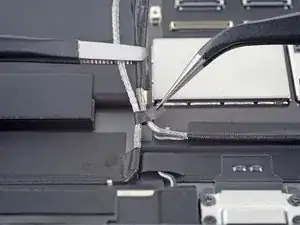
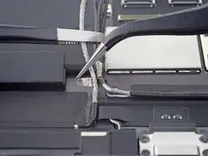
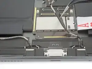
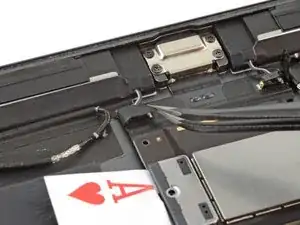
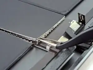
    • Use a pair of tweezers to unwrap the lower tape strip securing the antenna cables together.

    • Separate the two antenna cables.

    You don't need to unwrap the tape; you can use tweezers and separate the tape from the logic board and GNETLY lift the whole assembly above the bottom of the logic board.

    Gregg Stanley -

  24. s1KJYVl1NBMqe5qH
    s1KJYVl1NBMqe5qH
    4Ldqj4HxYFWOWcVI
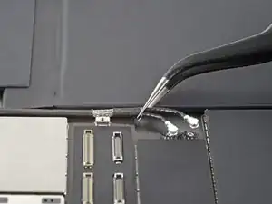
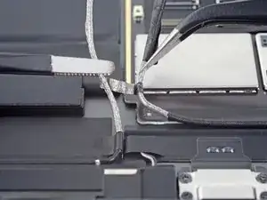
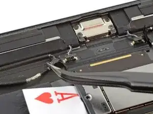
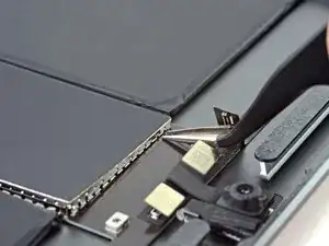
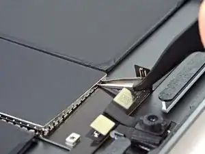
    • Use a pair of tweezers to peel the right antenna cable away from the logic board.

    • Fold both the left and right antenna cables out of the way.

    You don't need to unwrap the tape; you can use tweezers and separate the tape from the logic board and GNETLY lift the whole assembly above the bottom of the logic board.

    Gregg Stanley -

  25. WQAGrCBYSLhRNxYe
    WQAGrCBYSLhRNxYe
    wT15kLFtgTZSHmjw
    hjtZm1fJtZc4MkYZ
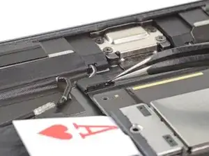
    • Use a pair of tweezers to peel up the tape covering the right speaker connector.

    • The right speaker connector will disconnect when you pull up on the tape.

    • Repeat for the left speaker connector.

  26. fpNt2NfZCsYJCUER
    fpNt2NfZCsYJCUER
    M1cV4cfuhR2ZuCVx
    QSbFCFdIPFGLGFPE
    • Use a pair of tweezers to remove the tape from the back of both speaker connectors.

  27. 3stggdmWNgfwbiNq
    3stggdmWNgfwbiNq
    xuWPEl1uXyuASsQU
    FwJvrITTgmBDQAAR
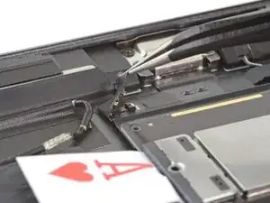
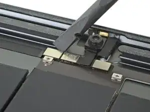
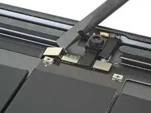
    • Use the flat end of a spudger to disconnect the headphone jack cable by lifting straight up on the press connector.

    • Repeat to disconnect the front camera and microphone assembly cables.

    On the LTE model, the microphone assembly connector on the left is a vertical connector and is below that screw post that you see in the photo. On the other side is another identical vertical connector that goes the the rear facing camera/power/volume buttons that needs to be disconnected too.

    Gregg Stanley -

  28. kZVuJxU2hLQKsmww
    kZVuJxU2hLQKsmww
    2KiAjaE2YPdqL2ug
    ffOP2URH6WZCMoJX
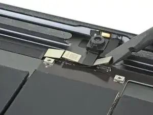
    • Use the pointed end of a spudger to disconnect the volume button cable by lifting straight up on the press connector.

    • Repeat to disconnect the rear camera and power button assembly cables.

    On the LTE version you do not need to do this step as you will have disconnected the main connector that I mentioned in the last step. However, you will need to disconnect the two cellular antenna connectors that are next to both vertical connectors mentioned earlier.

    Gregg Stanley -

  29. CJOOy2Ws3DM5rHSZ
    CJOOy2Ws3DM5rHSZ
    lJdUCaoTY5NI3uib
    • Use a Phillips screwdriver to remove the 1.3 mm-long screw securing the logic board shield.

  30. WFhFQsoWRflLiUva
    WFhFQsoWRflLiUva
    gYBY6n5CGHnWCbLo
    FuKfIYElOcf12m3h
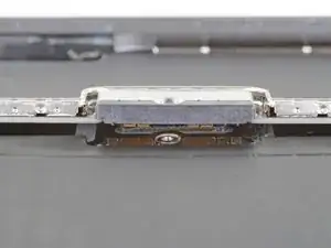
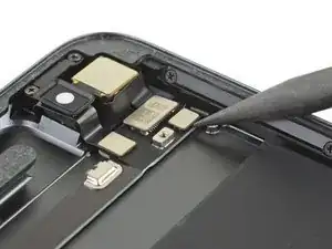
    • Insert the tips of a pair of tweezers into the gaps under the the logic board shield on the upper right corner.

    • Take care not to puncture or bend the battery with your tool—a punctured or bent battery may leak dangerous chemicals or cause a thermal event.

    • Pry up slightly to loosen the logic board shield.

    • Pivot the tweezers on the screw boss to avoid damaging the press connectors.

    On the LTE model, there is another smaller rectangular/square that you are NOT removing. Go further down and about 1" below the flex connections.

    Gregg Stanley -

  31. f2NQyuKvZnVJnZTC
    f2NQyuKvZnVJnZTC
    YBybBbtIgQ4mxJXI
    hKJiZKiQ1weCPCF2
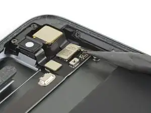
    • Insert the tips of a pair of tweezers into the gaps under the logic board shield on the upper left corner.

    • Pry up slightly to loosen the logic board shield.

    • Pivot the tweezers on the screw boss to avoid damaging the press connectors.

  32. MBgDHGIZrDsPtgOV
    MBgDHGIZrDsPtgOV
    igfXkkkOuAPsRrPU
    dSdYvH6WCi1okMWh
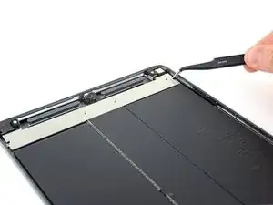
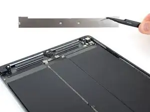
    • Insert the edge of an opening tool under the top edge of the logic board shield.

    • Pry up to loosen the shield.

    • Continue prying until you've loosened the entire top edge of the shield.

  33. AkCO5is2xbRgYtNV
    AkCO5is2xbRgYtNV
    xDkCxuskAbEj2fqy
    Eiji2XLXQ5ROplDk
    • Grip the logic board shield with your fingers.

    • Slowly lift the shield up and remove it.

    • Try to keep the logic board shield as straight as possible. You will be putting the shield back on later.

    Add a little bit of heat to the shield just enough to warm it up and it will peel up without deforming too much.

    Gregg Stanley -

  34. ieg2sKxXPXryQUgZ
    ieg2sKxXPXryQUgZ
    GNj5QnAhMipTekMO
    l6kDU3ANavNGlSlE
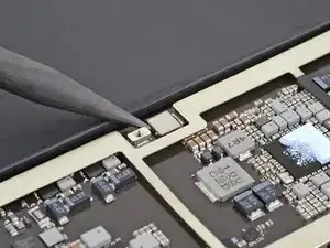
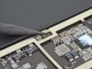
    • Use the pointed end of a spudger to disconnect the Smart Connector cable by lifting straight up on the press connector.

  35. tdUKmjRh2DYDtMHM
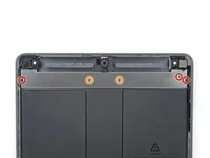
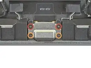
    • Use a Phillips screwdriver to remove the four screws securing the charging port to the rear case:

    • Two 2.4 mm-long screws

    • Two 1.7 mm-long screws

  36. e2HvgSod11pascJ4
    • Apply a heated iOpener to the top edge of the rear case for a minute.

    On the LTE version you can skip this step as the logic board does not extend to the right; skip to step 40.

    Gregg Stanley -

  37. 5fjmrCCelPjSiBQr
    5fjmrCCelPjSiBQr
    keKuaRPnbCxWJNXh
    wDhpKlMmH1jqnKiC
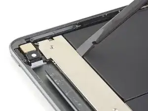
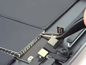
    • Insert an opening tool underneath the logic board arm near the rear camera.

    • Pry up the arm until you can slide in an opening pick underneath it.

  38. 4ZxgGN3pbLHviMIK
    4ZxgGN3pbLHviMIK
    fjCxkPpBYwgWVEPn
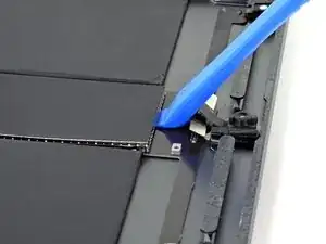
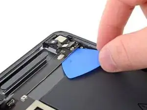
    • Push the opening pick up towards the rear camera to slice the adhesive under the logic board arm.

  39. BcHLZp3EsF4MFW4Y
    BcHLZp3EsF4MFW4Y
    RGFDpPZYem4MiX1p
    5EcOrsYqcdUEoYas
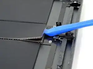
    • Insert another opening pick underneath the logic board arm.

    • Slide the opening pick towards the front camera to slice the adhesive underneath the arm.

  40. tFWfXMFbtMFJeUR1
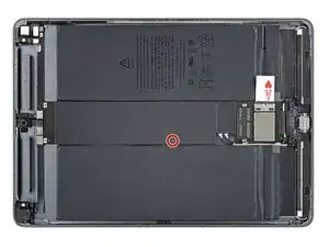
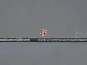
    • Apply a heated iOpener lengthwise down the center of the rear case to soften the logic board adhesive.

  41. uEHHr4nEnQToqRVw
    uEHHr4nEnQToqRVw
    ggC4vm5cFYYq1xoF
    OFPvFFWmNwI6HfpP
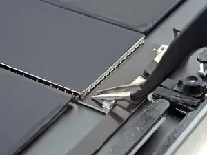
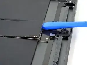
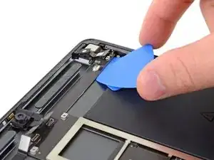
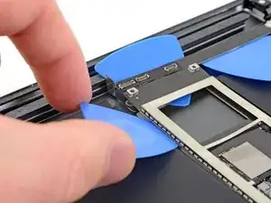
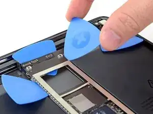
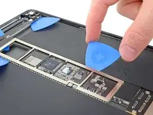
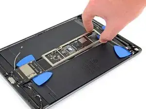
    • Insert an opening tool under the logic board next to the front camera.

    • Pry up the logic board until you can slide an opening pick underneath the logic board.

    • Take care to not slice the headphone jack cable.

  42. nxbmHPqJXaCpsmlv
    nxbmHPqJXaCpsmlv
    gGyghJduHlUuwAdo
    • Push the opening pick underneath the logic board to slice the adhesive.

  43. LybVch1JnYB6oUts
    LybVch1JnYB6oUts
    hvnCMP3AgIl1hKT5
    JioR1v2eJtniSP6N
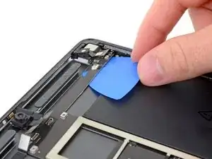
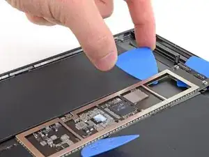
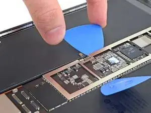
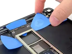
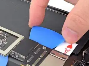
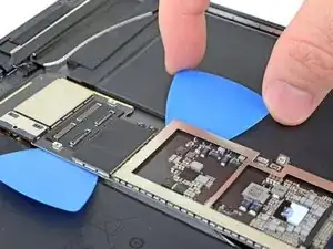
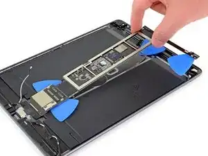
    • Insert another opening pick under the upper left corner of the logic board.

    • Slide the pick down towards the bottom of the iPad to slice the adhesive.

  44. ylOcRXcUakGqeORX
    ylOcRXcUakGqeORX
    j2IoMfrpHMLpHuMA
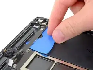
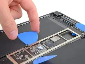
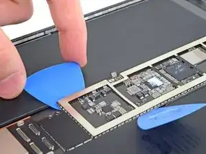
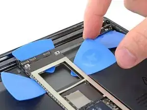
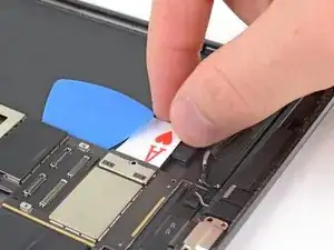
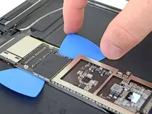
    • Slide the opening pick down the left edge of the logic board until you get near the Smart Connector cable.

    • Take care not to slice through the Smart Connector cable.

  45. b2JwDIYGaKOShw4U
    b2JwDIYGaKOShw4U
    jKDYdIPjRPMASOPk
    igBdh46QGfeUdgR6
    • Use a spudger to move the Smart Connector cable behind the opening pick.

  46. xaEsW6dUSbOhf5UA
    xaEsW6dUSbOhf5UA
    EQ5akayJnLnqGBeB
    • Slide the opening pick past the Smart Connector cable and down to the antenna connectors.

    • If you have trouble, apply a few drops of isopropyl alcohol to the edge of the logic board, wait a minute, and try again.

  47. IrKOwyOQkaVnlCJ4
    IrKOwyOQkaVnlCJ4
    Ty6nXAZDub26njgO
    xYHobrtp3Y2tJDg1
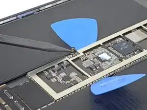
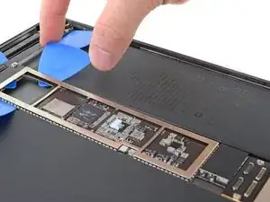
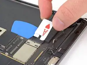
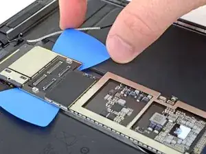
    • Insert an opening pick under the upper right edge of the logic board.

    • If you have trouble, apply a few drops of isopropyl alcohol to the edge of the logic board, wait a minute, and try again.

    • Slide the pick down towards the bottom of the iPad to slice the adhesive.

  48. iqdb3hBAaUWUUNVA
    iqdb3hBAaUWUUNVA
    b1AQRvdbFDYMWIaZ
    NcJGpMCtQ2st6QAS
    • Slide the opening pick down the right edge until you encounter the battery connector.

  49. ZDU1Oa4qxGF1GAoL
    ZDU1Oa4qxGF1GAoL
    WcKheJMALBrRwjeL
    • Remove the battery blocker.

  50. t6aQH5ipo2V5AZh4
    t6aQH5ipo2V5AZh4
    dEmcP4SEDGQKDbNe
    Mv4MYyioNQvJIeIM
    • Slide the left opening pick down the left edge to the speaker connectors.

  51. Vw2ZgBoLSdaBNXpJ
    Vw2ZgBoLSdaBNXpJ
    OflxlFYSwaOATFgC
    3oeTTYSD4LBfPyll
    • Slowly lift the logic board up and pull the charging port out of its recess.

    • If you can't lift up the logic board, identify where it is stuck and use an opening pick to slice the adhesive there.

    • You can also apply a few drops of high concentration (90% or higher) isopropyl alcohol where it's extra stuck.

  52. 2AND14inuNJk3uVa
    • Remove the logic board.

    • During reassembly, follow this guide if you are using a pre-cut adhesive card to reattach the logic board to the rear case.

Conclusion

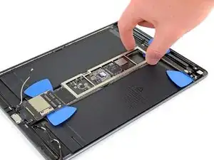
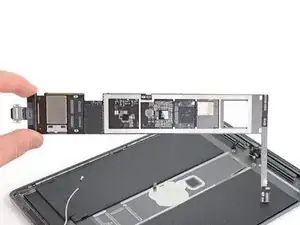
Compare your new replacement part to the original part—you may need to transfer remaining components or remove adhesive backings from the new part before you install it.

To reassemble your device, follow these instructions in reverse order.

Take your e-waste to an R2 or e-Stewards certified recycler.

Repair didn’t go as planned? Try some basic troubleshooting, or ask our iPad Air 3 Answers community for help.


Robert Boyd

Member since: 01/02/21

26261 Reputation

0 comments