
Introduction
Use this guide to replace the logic board.
-
-
Before beginning any work on your iMac: Unplug the computer and press and hold the power button for ten seconds to discharge the power supply's capacitors.
-
-
-
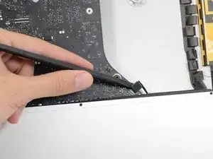
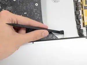
Starting on the left of the display, near the power button, insert the iMac Opening Tool into the gap between the glass panel and the rear enclosure.
-
-
-
Use the tool like a pizza cutter—roll it along through the gap, and it will cut the foam adhesive through the center.
-
Run the tool up along the left side of the display.
-
-
-
Starting from the top right corner of the iMac, wedge a plastic card between the display and frame.
-
-
-
Gently twist the plastic card sideways to create a gap between the display and frame.
-
Move slowly and be careful not to stress the display glass too much—you only need to make a gap of about 1/4".
-
-
-
Slide the card toward the center of the display to cut any of the remaining adhesive along the top right corner of the iMac.
-
-
-
Wedge the plastic card into the top right corner once again, and leave it there to prevent the adhesive from resticking.
-
-
-
Insert a second plastic card into the gap between the display and frame near the top left corner of the iMac.
-
-
-
With both plastic cards inserted as shown near the corners, gently twist the cards sideways to increase the gap between display and case.
-
Begin to lift the top of the display up from the frame.
-
-
-
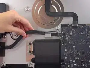
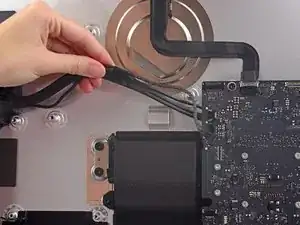
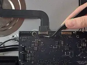
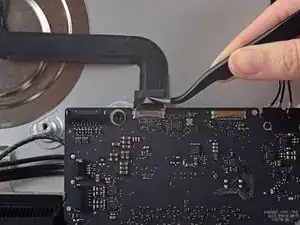
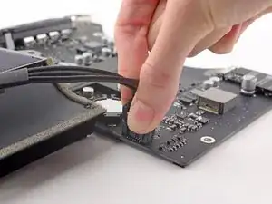
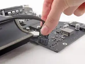
Use a pair of tweezers to flip up the metal retaining bracket on the display data cable.
-
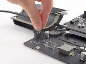
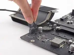
Carefully pull the display data cable from its socket on the logic board.
-
-
-
While holding the display up with one hand, use the other hand to unplug the display power cable.
-
-
-
Grasp the small tab at the end of one of the bottom edge display adhesive strips and pull the adhesive toward the top of the iMac to remove it.
-
Repeat this step with the other adhesive strip and remove it.
-
-
-
Lift the display up from the frame and remove it from the iMac.
-
It may be necessary to slowly lift from one side, to peel against the remaining adhesive.
-
-
-
Remove the following five Phillips screws holding the lower support bracket in place:
-
Four 3.2 mm screws
-
One 1.7 mm screw
-
-
-
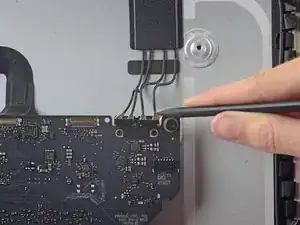
Use the tip of a spudger to push on either side of the right speaker cable connector to walk it out of its socket on the logic board.
-
-
-
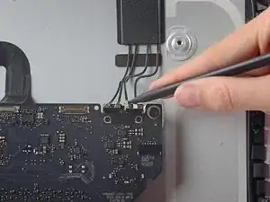
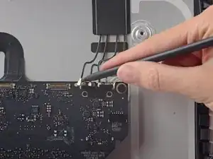
Insert the tip of a spudger between the right speaker and the antenna cable that is routed into the speaker's right side.
-
Run the spudger down along the right side of the speaker to pry the antenna cable from its channel in the right speaker.
-
-
-
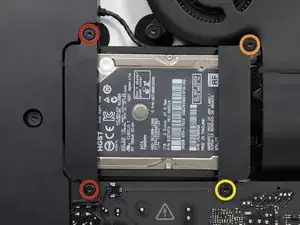
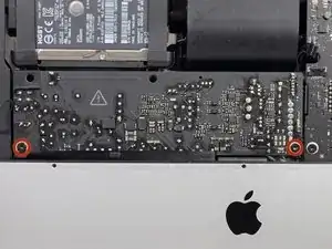
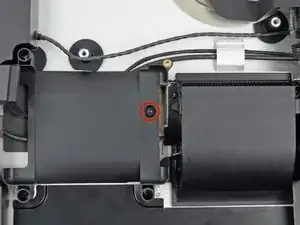
Remove the following screws securing the hard drive bracket to the rear enclosure:
-
Two 21 mm T10 Torx screws from the left-hand hard drive bracket.
-
One 9 mm T10 Torx screw.
-
One 27 mm T10 Torx screw.
-
-
-
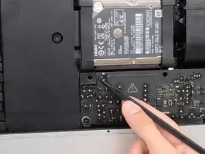
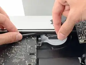
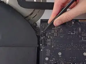
Use the tip of a spudger to push each side of the power button cable connector and gently walk it out of its socket.
-
-
-
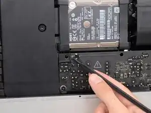
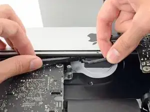
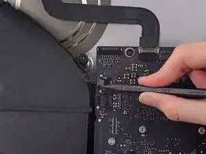
Use the tip of a spudger to push each side of the power supply control cable connector and gently walk it out of its socket.
-
-
-
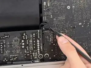
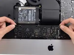
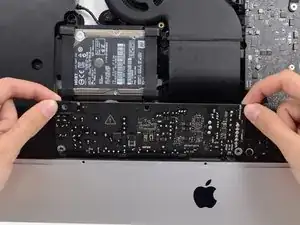
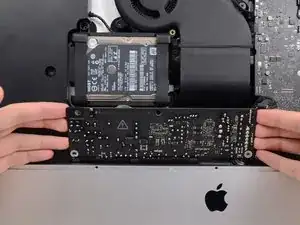
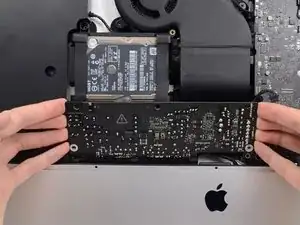
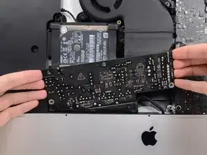
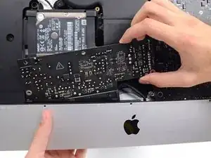
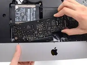
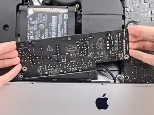
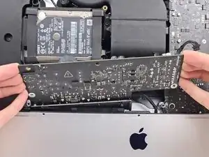
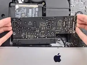
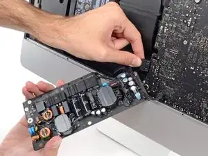
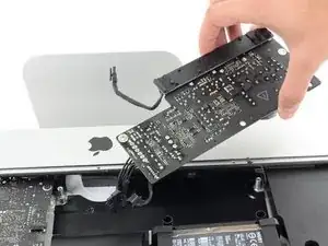
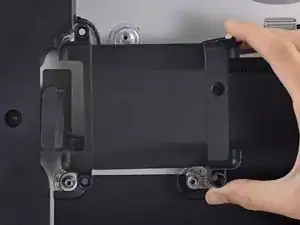
Pull the power supply slightly up and out from the rear enclosure.
-
Rotate the power supply counterclockwise, lifting the right side up about an inch higher than the left.
-
-
-
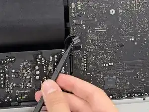
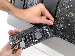
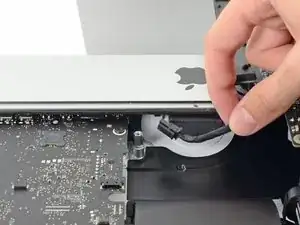
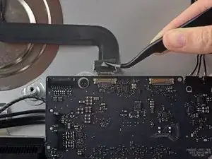
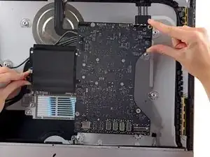
Squeeze the tab on the back side of the DC power cable connector and pull it straight out of its socket on the back of the logic board.
-
-
-
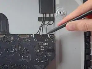
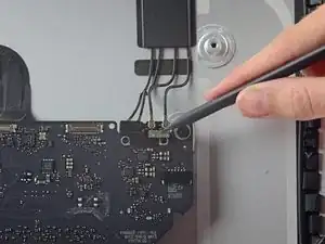
Use the flat end of a spudger to press the clip on the side of the AC inlet cable connector inward.
-
While pressing on the release clip with the spudger, grasp the AC inlet cable, and pull the connector straight out of its socket.
-
-
-
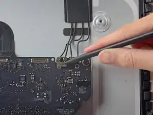
Use the tip of a spudger to push the fan cable connector out of its socket on the logic board.
-
-
-
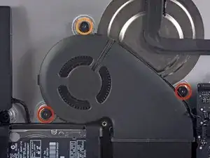
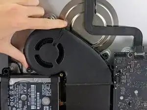
Remove the following screws securing the fan to the rear enclosure:
-
Two 12.5 mm T10 screws
-
One 9.9 mm T10 screw
-
-
-
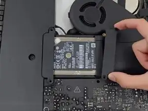
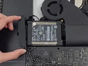
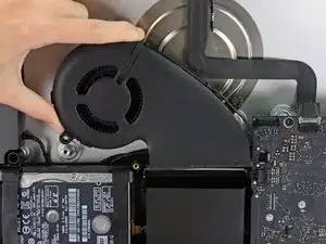
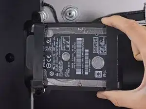
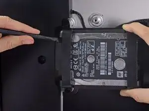
Lift the hard drive from the edge nearest the logic board and pull it slightly out of its recess.
-
-
-
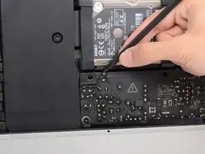
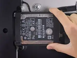
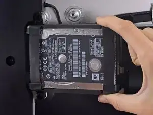
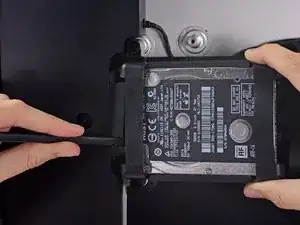
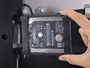
Use a spudger to disconnect the single SATA power and data combo cable by gently prying its large plastic connector away from the hard drive.
-
-
-
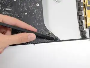
De-route the left speaker cable by pulling it straight up out of the retaining clip in the back of the rear enclosure.
-
-
-
In a similar fashion as the previous step, de-route the combo SATA data/power cable up out of the retaining clip.
-
-
-
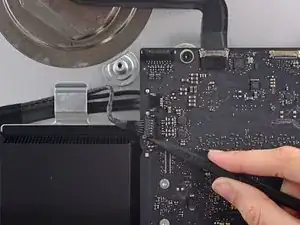
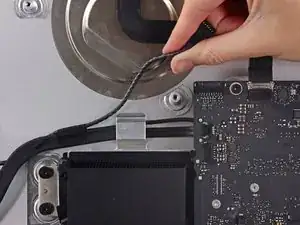
Use a pair of tweezers to flip up the metal retaining bracket on the iSight camera cable connector.
-
Pull the iSight camera cable straight out of its socket on the logic board.
-
-
-
Use the tip of a spudger to disconnect each of the four antenna connectors from the AirPort/Bluetooth card.
-
-
-
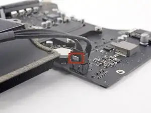
Use the flat edge of a spudger to pry the headphone jack cable connector from its socket on the logic board.
-
-
-
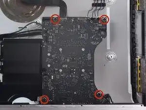
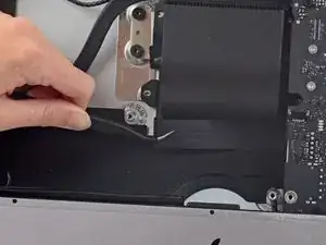
Remove the following screws securing the exhaust duct to the rear enclosure:
-
Two 6.3 mm T8 screws
-
Two 4.7 mm T8 screws
-
-
-
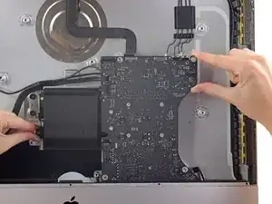
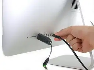
Use a USB flash drive and/or ethernet cable to keep the logic board aligned while you screw it in.
-
-
-
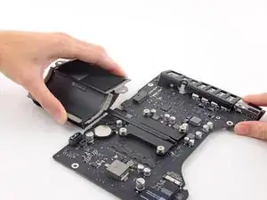
While pressing on the clip with your thumb, lift and disconnect the SATA data connector from its socket on the logic board.
-
-
-
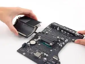
Grasp the hard drive power connector and gently pull it out of its socket on the logic board.
-
-
-
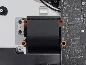
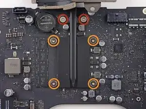
The following screws secure the heat sink to the logic board:
-
Remove the two T8 screws from the exhaust port end of the heat sink.
-
Loosen, but do not remove, the four captive T8 screws securing the CPU end of the heat sink.
-
-
-
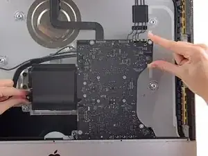
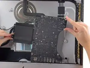
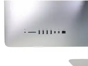
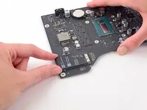
During reassembly of the logic board, pay attention to the position of the I/O connectors. When the board is back in the case, insert a USB or Thunderbolt cable into one of the connectors to align it perfectly.
-


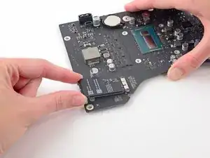
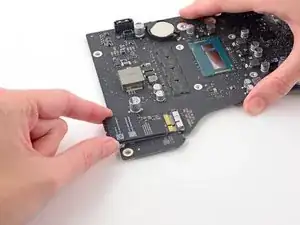
To reassemble your device, follow these instructions in reverse and use our Adhesive Strips Guide to reattach the display glass.

The wedge is an extremely tight fit for this model. I was worried that the amount of force needed to use it as shown might damage the stand, so I used it with the long side down instead. It worked fine that way and didn’t need anywhere near as much force to insert.
roberttrevellyan -