Introduction
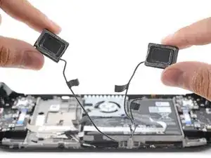
Use this guide to replace the speakers in your Steam Deck LCD. The left and right speakers are tethered into a single cable, so they need to be replaced as a pair.
Remember: follow general electrostatic discharge (ESD) safety procedures while repairing your device.
-
-
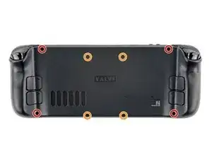
Use a Phillips driver to remove the eight screws securing the back cover:
-
Four coarse thread 9.5 mm-long screws
-
Four fine thread 5.8 mm-long screws
-
-
-
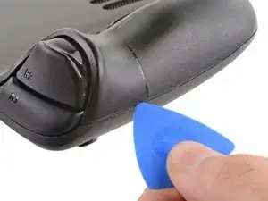
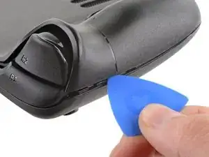
Insert an opening pick into the thin gap between the back cover and the front shell, along the edge of the right grip.
-
Pry up on the back cover to release it from the locking clips.
-
-
-
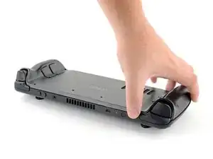
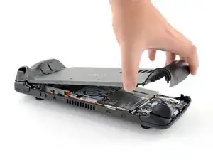
Grip the back cover at the opening you just created and pull it up and away from the device to unclip the long edges.
-
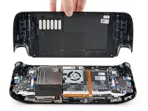
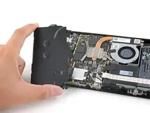
Remove the back cover.
-
-
-
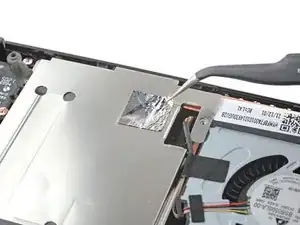
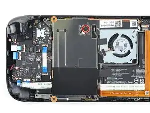
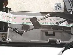
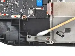
Use a pair of tweezers to remove the piece of foil tape covering the hidden screw on the board shield.
-
-
-
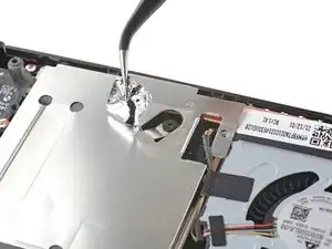
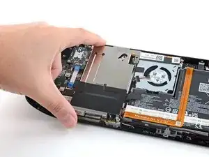
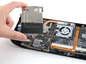
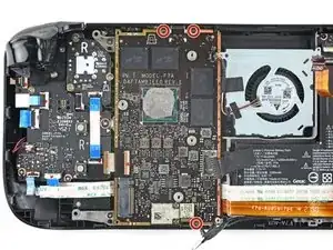
Use a Phillips driver to remove the three screws securing the board shield:
-
One 3.4 mm screw
-
Two 3.7 mm screws
-
-
-
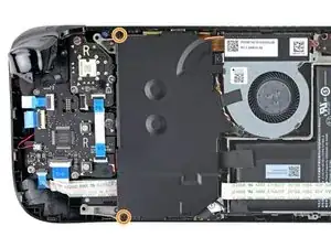
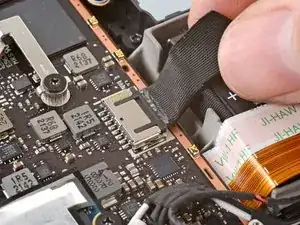
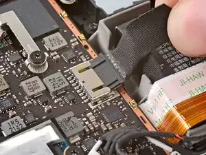
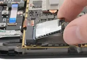
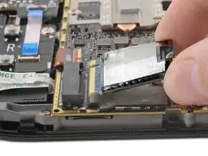
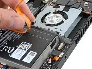
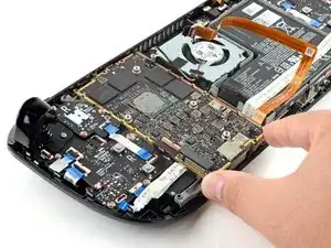
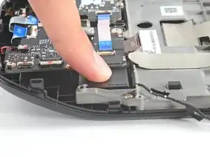
Grip the battery cable by its pull tab and pull it directly away from the motherboard to disconnect it.
-
-
-
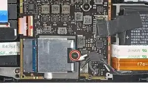
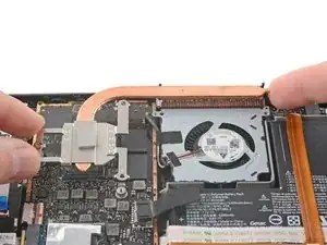
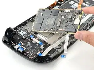
For original Steam Decks: Use a Phillips driver to loosen and remove the two screws securing the heatsink to the motherboard:
-
One captive 3.5 mm screw
-
One 3.4 mm screw
-
For refreshed Steam Decks: Use a Phillips driver to remove the three screws securing the heatsink to the motherboard:
-
Two 2.9 mm screws
-
One 3.7 mm screw
-
-
-
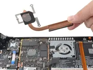
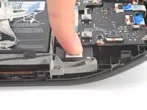
Use a pair of tweezers to grip the edges of the fan connector and pull up to disconnect it from the motherboard.
-
-
-
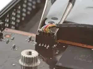
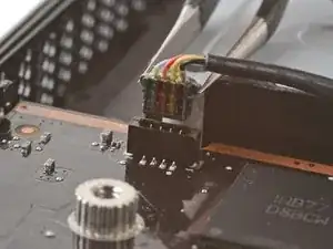
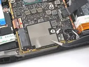
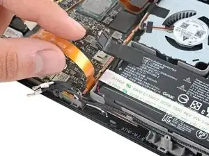
Use a pair of tweezers to grip the edges of the speaker connector and pull up to disconnect it from the motherboard.
-
-
-
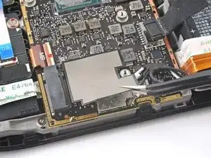
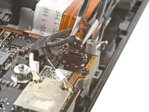
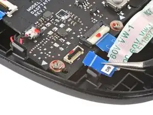
Use a pair of tweezers to grip the antenna connector close to its base.
-
Pull straight up to disconnect the cable.
-
Repeat for the second antenna cable.
-
-
-
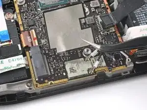
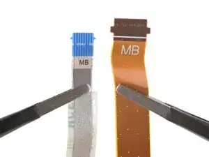
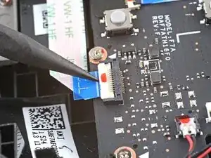
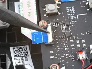
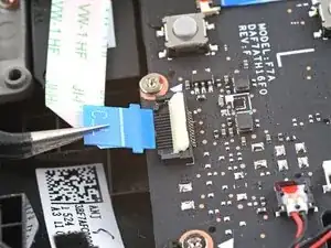
Use the pointed end of a spudger to lift up the small locking flap on the display cable's ZIF connector.
-
Use a pair of tweezers to slide the cable out of its connector.
-
-
-
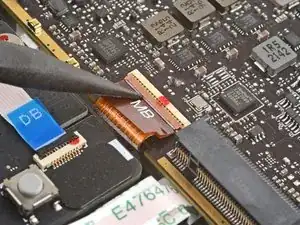
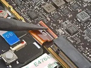
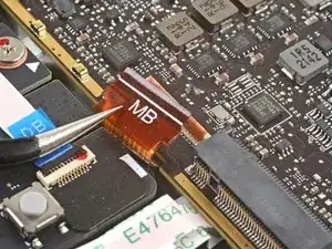
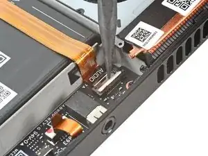
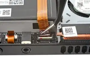
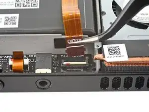
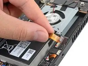
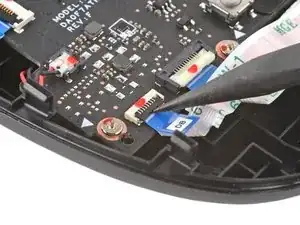
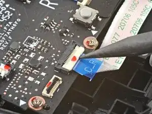
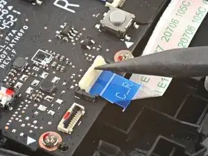
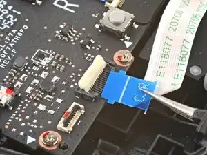
Use the pointed end of a spudger to lift up the small locking flap on the audio cable's ZIF connector.
-
-
-
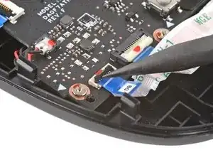
Use the pointed end of a spudger to lift up the small locking flap on the button board cable's ZIF connector.
-
Use a pair of tweezers to slide the cable out of its connector.
-
-
-
Use the pointed end of a spudger to lift up the small locking flap on the button board interconnect cable's ZIF connector on the left button board.
-
Use a pair of tweezers to slide the cable out of its connector.
-
-
-
Use the pointed end of a spudger to lift up the small locking flap on the button board interconnect cable's ZIF connector on the right button board.
-
Use a pair of tweezers to slide the cable out of its connector.
-
-
-
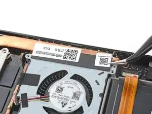
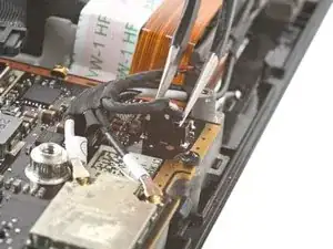
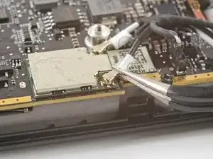
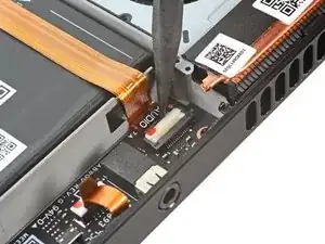
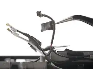
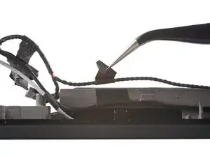
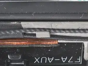
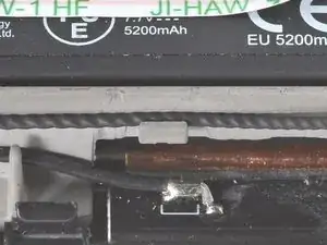
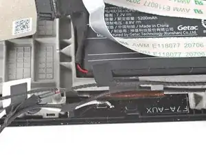
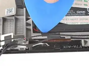
Use a pair of tweezers to peel up the tape bundling the speaker wire to the Wi-Fi antenna cables.
-
-
-
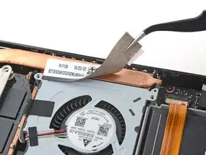
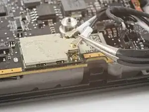
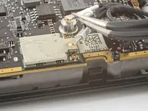
Use a pair of tweezers to peel up the various strips of black tape routing the speaker wire along the bottom edge of the chassis.
-
-
-
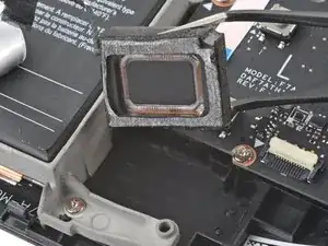
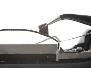
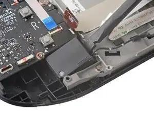
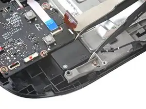
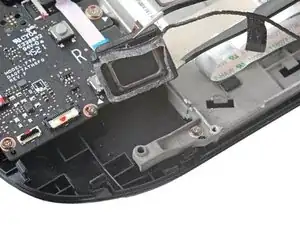
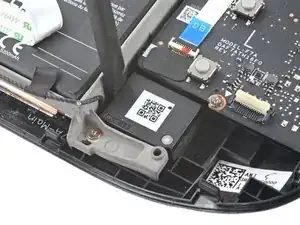
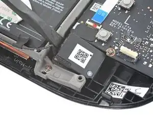
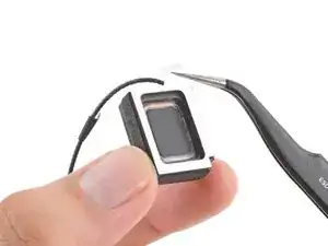
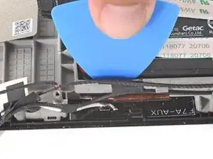
Insert the flat end of a spudger between the right speaker and the frame.
-
Pivot the spudger up to separate the speaker from the light adhesive securing it against the front shell.
-
-
-
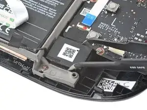
Insert the flat end of a spudger between the left speaker and the frame.
-
Pivot the spudger up to separate the speaker from the light adhesive securing it against the front shell.
-
-
-
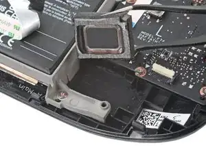
Use adhesive remover or isopropyl alcohol (>90%) to remove any remaining residue. Wipe with a cotton swab or microfiber cloth until all the adhesive residue is gone.
-
Allow any leftover isopropyl alcohol to completely evaporate before reassembly.
-
-
-
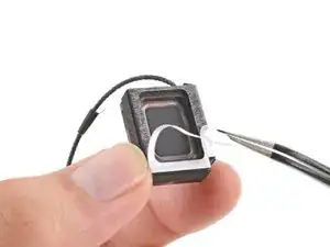
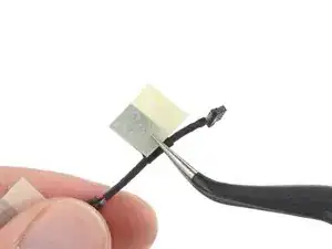
Peel off and discard the liners on the speakers themselves, exposing the adhesive underneath.
-
-
-
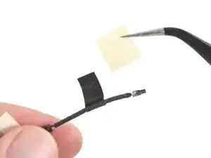
To ensure proper cable management, stick one speaker cable adhesive to the top edge of the chassis, leaving ~3 mm at the top unstuck.
-
Use an opening pick to wrap the adhesive over the edge of the battery tray, sticking it to the inside edge.
-
Repeat for the second cable adhesive, and continue reassembly.
-

To reassemble your device, follow these instructions in reverse order.
Take your e-waste to an R2 or e-Stewards certified recycler.
Repair didn’t go as planned? Try some basic troubleshooting, or ask our Steam Deck answers community for help.

3 comments
Hello.
Thanks for your great doc.. I got a problem on my steam deck that the left speaker sounds louder and more clear than the right side. Tried many games and other music resourses, also checked the balance setting in desktop mode, right side seems to be a liitle weaker.
Especially the treble range is especially obviously like this.
Do you think if it Is a hardware failure? Did you ever see this ptoblem?
Thanks a lot.
Hey there,
Guess im a bit late to answer you but, the thing you are saying is a firmware issue and “not” a hardware issue. Pretty much every steam deck have this issue. I even changed my speakers hoping to fix this problem… but no.. same results. The left speaker is louder than the right one by default, for some reason. Even sometimes you will hear some crackling sound coming from only the left speaker when the volume is too loud. Idk why this firmware issue wasn’t fix yet. But anyway!
Good teardown and replacement guide! I managed to damage my speaker wire while doing something else and this made it clearer how to get that darn buried right side out and replaced. I was a bit worried at first due to just how much disassembly was needed to get to it. In the end, not difficult, just needed some patience with properly reattaching the ribbon cables and a few tips from the guide helped alot.
Raaben -