Introduction

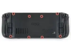
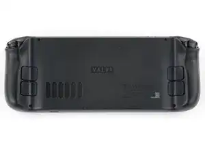
This guide demonstrates how to remove the motherboard in your Steam Deck OLED.

  1. wg1CPbiBgYbiTVlf
    wg1CPbiBgYbiTVlf
    nJjXUM3KksnJHIgN
    mLdVpQ6WWvINGWuE
    • Turn on your Steam Deck and allow the battery to discharge below 25% before starting your repairs, as a charged lithium-ion polymer battery can be dangerous if accidentally punctured.

    • As an extra precaution, Valve recommends putting your Steam Deck into battery storage mode within the BIOS before starting any internal repairs. Read how to do that here.

    • Power down your Steam Deck and unplug any cables.

    • If you have a microSD card installed, make sure to remove it before opening the Steam Deck. If you attempt to remove the back cover with it still installed, it could snap right in half.

    • During your repair, it can be helpful at times to lay the Steam Deck face-down in its case to protect the thumbsticks and prevent wobble.

  2. CU2nvWsgJGWI2Rut
    CU2nvWsgJGWI2Rut
    HUaIpoLKT3gGOD53
    • Use a T6 Torx driver to remove the eight 5.8 mm‑long screws securing the back cover.

    • Throughout this repair, keep track of each screw and make sure it goes back exactly where it came from.

  3. rEBEVxNkrDU5dsek
    rEBEVxNkrDU5dsek
    rIRRhvkBKVWODhWI
    A4aS52mtPxxkwit5
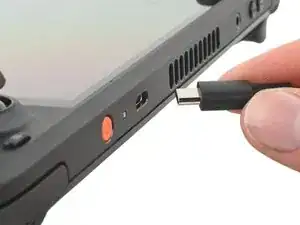
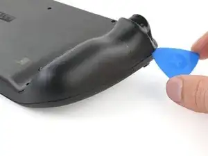
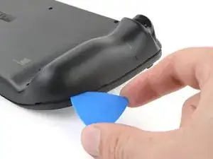
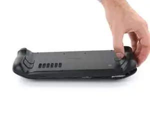
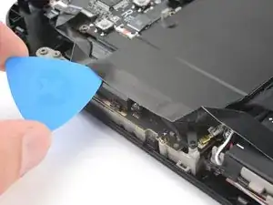
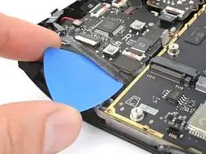
    • Insert an opening pick at an upward angle between the back cover and the front shell near one of the triggers.

    • If you can't insert your pick here, try along the top or bottom edges of the Steam Deck OLED before sliding it toward the handle.

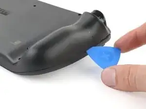
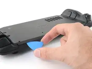
    • Slide your pick along the edge of the handle to release the clips securing it to the front shell.

  4. yYcl1PRUGUuYu2AV
    yYcl1PRUGUuYu2AV
    Z61KAZVNuuuFxgBL
    5ji5HRJa5qu1niLI
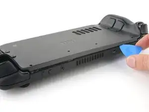
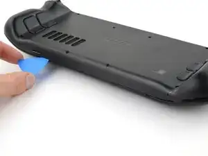
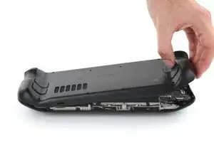
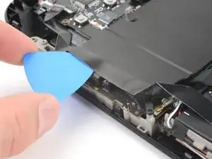
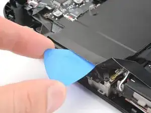
    • Reinsert your pick and slide it along the top and bottom edges until the back cover feels loose.

  5. 3hO2o6jhWtTFtqUB
    3hO2o6jhWtTFtqUB
    HZa1Pau2KaJcrM1I
    2pXBrjoLgvKGSFGx
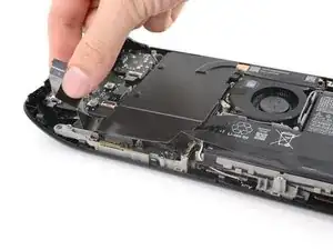
    • Grip the unclipped handle and pull it away from the front shell to release the remaining clips.

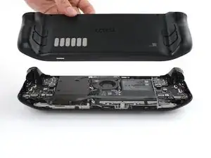
    • Remove the back cover.

  6. OKJYYpHQNvn4X1nk
    OKJYYpHQNvn4X1nk
    GaA5rrvDLfGCHRBc
    d6WmlRapenltwItT
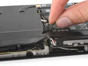
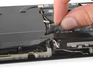
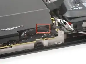
    • Grip the battery cable pull tab, located to the left of the battery.

    • Firmly pull the battery cable straight away from the motherboard shield (toward the battery) to disconnect it.

    • This bundled cable is fairly stiff. If you're having trouble, re-grip the pull tab close to the head of the connector and gently walk it side-to-side as you pull.

    • If the cable pull-tab feels fragile or rips during this process, remove the motherboard shield and disconnect the cable using a spudger.

    • When the battery cable comes free, it might push up on the motherboard shield. Don't worry, as this won't damage anything.

    The pull tab can come off revealing the wires. The instructions should be updated to reflect that catch.

    Khurram Tariq -

  7. 2GFAlFaM62QyIqmL
    2GFAlFaM62QyIqmL
    IMJHriGYVTmlmpNE
    AuiMjoWPJP3rNUSW
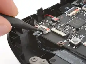
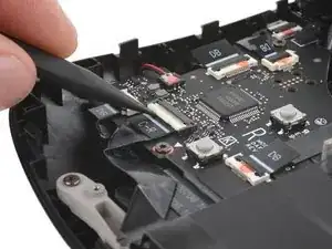
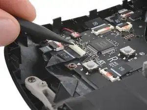
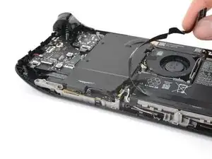
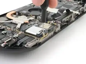
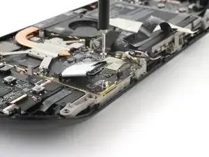
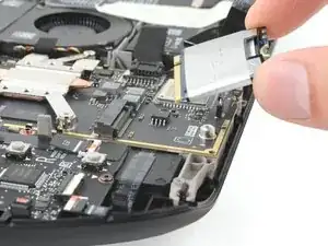
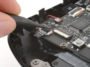
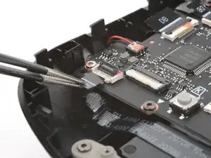
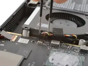
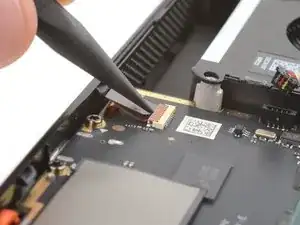
    • Use a spudger to flip up the small white locking flap on the right button board interconnect cable ZIF connector.

    • Use tweezers or your fingers to grip the cable's pull tab and slide it straight out of its socket to disconnect it.

    • The pull tab may be labelled C‑R.

  8. JxgFSn411iuTmHXV
    JxgFSn411iuTmHXV
    hsjSQjeqb1DHbNg5
    W11KlQgrfpiETkee
    • The interconnect cable is adhered to the motherboard shield.

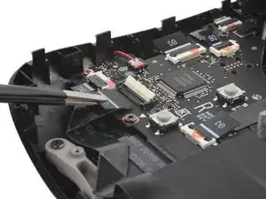
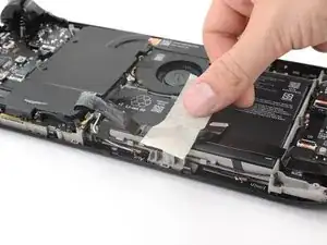
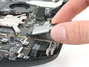
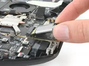
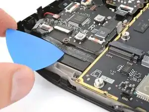
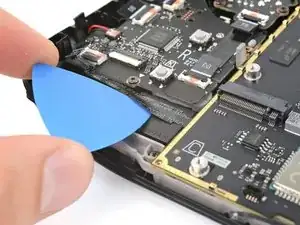
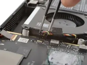
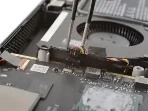
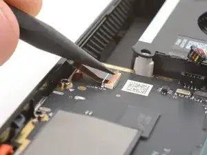
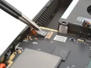
    • Insert an opening pick between the interconnect cable and the motherboard shield.

    • Be careful not to crease or tear the cable.

    • If you're having trouble inserting a pick, lightly heat the cable using an iOpener or a hair dryer.

    • Slide your pick along the shield to separate the cable.

    The adhesive is quite strong and it causes the cable to bend. Don't separate the cable from the shield and instead unscrew the shield and lift it towards the right gently to create space to access the SSD.

    Khurram Tariq -

  9. xVsAVwm5nYRCPlYS
    xVsAVwm5nYRCPlYS
    FrqAcp3usMH5YIQG
    I1IogadgJ2WBTh4T
    • During the rest of the repair, it may be helpful to move the interconnect cable over the battery and out of the way of the motherboard shield.

    • Be careful not to crease or strain the cable, as it's still adhered to the battery.

    • Tape the cable in place away from the motherboard shield.

  10. wnPrhtu1rYiX1ZbM
    wnPrhtu1rYiX1ZbM
    wnO5PMcmgZnCq2sG
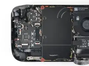
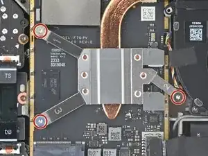
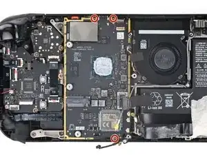
    • Use your T6 Torx driver to remove the two 3.8 mm‑long screws securing the top left and bottom left corners of the motherboard shield.

  11. AUdJWmS2vDeLnEK3
    AUdJWmS2vDeLnEK3
    21UXwEKEDILPei41
    WZTF3bcws1Hg3Aod
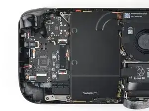
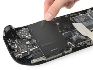
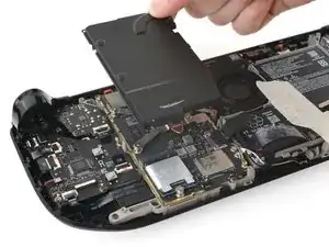
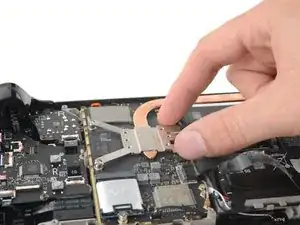
    • If the speaker cable is taped to the bottom edge of the motherboard shield, gently peel it off.

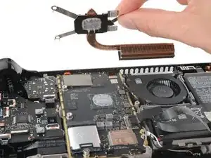
    • Remove the motherboard shield.

  12. l3nfN6tVdOc2Sx1a
    l3nfN6tVdOc2Sx1a
    1YGWDONVYYbBFVWZ
    gXnISrVeocjEFGZC
    • Use your T6 Torx driver to remove the 3.3 mm‑long screw securing the SSD.

    • The SSD will pop up to a slight angle as you remove the screw.

  13. dZBBnLyL46gmX3fW
    dZBBnLyL46gmX3fW
    YnBPnYZpYG6hVvGV
    j42xEdZnSbDvgdLP
    • Grip the end of the SSD and pull it away from its M.2 board connector to remove it.

    • Remove the SSD.

    • During reassembly, insert the SSD at a slight angle into its socket and hold it against its screw post as you install its screw.

  14. 2DHFGXiikM4EDatt
    • Use your T6 Torx driver to remove the three 3.3 mm‑long screws securing the heat sink.

    • During reassembly, install the screws in the order marked on the heat sink mounts: 1, 2, then 3.

  15. Z4gy5udSqHPcH11U
    Z4gy5udSqHPcH11U
    PyfPTXtJofQhIZPj
    • Lift the heat sink from the motherboard and remove it.

    • Depending on the age of your device, this might require some force. A twisting motion may help loosen the thermal paste.

    • Before reinstalling the heat sink, follow this guide to clean the heat sink and APU and reapply thermal paste.

  16. 6JVtOCFea5R1ZjG3
    6JVtOCFea5R1ZjG3
    wfi4d4Kx6WjS2FkM
    pAwDVjssOigIeAvc
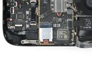
    • Use the point of your spudger to flip up the small black locking flap on the right button board ZIF connector in the bottom left corner of the board.

    • Use tweezers or your fingers to grip the pull tab and slide the cable straight out of its socket to disconnect it.

  17. dadnGRglDoIXNyHc
    dadnGRglDoIXNyHc
    DUwTghhsDQZOGRHY
    DkXOSNDqvDAUgZAK
    • Adhesive secures the right button board cable to the speaker.

    • Slide an opening pick between the left side of the cable and the speaker.

    • If the adhesive feels stubborn, lightly heat the cable with an iOpener or hair dryer.

    • Slide your pick toward the motherboard to separate the adhesive securing the cable.

  18. QTmuGN5SuKIN1TOv
    QTmuGN5SuKIN1TOv
    RxciGNExFaNWRGpS
    1vKdDCCHbKQdqsd3
    • Use blunt nose tweezers to grip the edges of the fan connector and walk it side-to-side out of its socket to disconnect it.

    • Don't pull on the cables—only pull on the connector body.

    • During reassembly, insert the connector gently. Make sure the exposed colored wires within the connector face away from the fan.

    • Don't force the connector into the socket, as you might damage the fragile internal pins.

  19. fZpBHAbVMitIHruh
    fZpBHAbVMitIHruh
    M5QMJvMiulCOXHCV
    Ahli1HfFaVKmWKV2
    • Use the point of your spudger to flip up the small locking flap on the audio board ZIF connector in the upper right corner of the motherboard.

    • Use tweezers or your fingers to grip the cable's pull tab and pull it straight out of its socket to disconnect it.

  20. nB26j1MZLiSqCXvJ
    nB26j1MZLiSqCXvJ
    wcUflPuNCKQSnZmq
    aTDsRijOeC2BfJXL
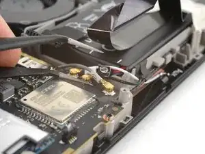
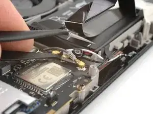
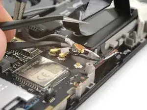
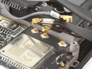
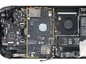
    • Slide one arm of angled tweezers under the metal neck of the gray antenna cable connector in the bottom right corner of the motherboard.

    • Gently lift the connector to disconnect it.

    • Don't lift the cables themselves—lift only on the metal necks of the connectors.

  21. UpgjwbXNORPOkkVN
    UpgjwbXNORPOkkVN
    RpKoBxDvMkVKUbVE
    tVv3tZY32GDHGJoM
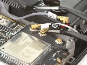
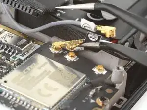
    • Repeat the previous step to disconnect the white and black antenna cable connectors.

    • During reassembly:

    • Note the correct socket for each connector—the white cable connects to the top socket, the black cable to the middle socket, and the gray cable to the bottom socket.

    • Hold each connector in place over its socket and press down with the flat end of your spudger until the connector snaps into place.

  22. KoMgyCDBdRWglYvN
    KoMgyCDBdRWglYvN
    FFIpqgOPAUN3xABq
    4ky1oED4DKidae4o
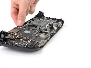
    • Use blunt nose tweezers to grip the edges of the speakers connector and walk it side-to-side out of its socket to disconnect it.

    • Don't pull on the cables—only pull on the connector body.

    • During reassembly, insert the connector gently. Make sure the exposed colored wires within the connector face away from the motherboard.

    • Don't force the connector into the socket, as you might damage the fragile internal pins.

  23. 2eKRMTCssGC4L1vw
    2eKRMTCssGC4L1vw
    oWZAHkAvSslQQ2QC
    • Use your T6 Torx driver to remove the three 3.7 mm‑long screws securing the motherboard.

  24. E6NnBpaScNLKitKZ
    E6NnBpaScNLKitKZ
    ESgqUYDMwGdnOJUH
    WKsyuVQtFLnSdSub
    • Be careful not to strain the screen cable, as it's still connected to the underside of the motherboard near the bottom right corner.

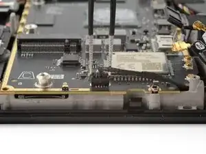
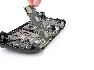
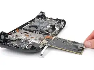
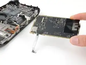
    • Lift the top edge of the motherboard and flip it over the bottom edge of the frame to access the screen cable underneath.

  25. BXjCH1oZFcWxX6IC
    BXjCH1oZFcWxX6IC
    6sruYIgUQMWQDkO3
    VI4iGWwFU1PpKwOf
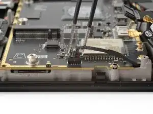
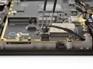
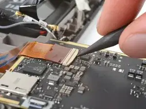
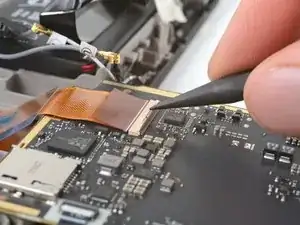
    • Use the point of your spudger to flip up the locking flap on the outside edge of the screen ZIF connector.

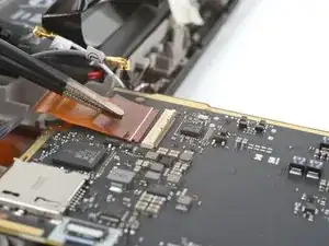
    • Use tweezers or your fingers to grip the screen cable pull tab and slide the cable straight out of its socket to disconnect it.

  26. NlK4GEvQlfkkfRTM
    • Remove the motherboard.

Conclusion

To reassemble your device, follow these instructions in reverse order.

Clay Eickemeyer

Member since: 19/09/22

65196 Reputation

0 comments