Introduction

  1. gEtH4L1kZ4oQbRbR
    gEtH4L1kZ4oQbRbR
    eIg51RPwZrOSsmJp
    oG2nypRSTDyEOx2O
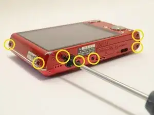
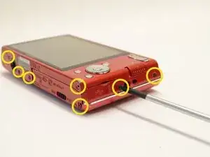
    • Begin by placing the camera flat against a surface and remove the nine (9) black screws. Each screw is of the same length and can be used interchangeably

    • Note: There are two (2) screws on each side, and five (5) on the bottom edge.

  2. GXgfjnRBDkTYfH3a
    GXgfjnRBDkTYfH3a
    nHBtReACUmmyKP1I
    ITEPPkaMWsaQAGwd
    • Use a plastic opening tool to carefully pry off the front casing.

    • Be careful to not to force the casing off. Simply move around the entire case separating where needed.

  3. YwjOJiFKiAbpes22
    YwjOJiFKiAbpes22
    S4BPtEjs5NO1R2nE
    DsEB1UfiFvYAmKEO
    • Flip the camera over 180 degrees and similarly pry off the rear casing.

  4. kXQkiHcFwLXNxvuS
    kXQkiHcFwLXNxvuS
    kWNGWIbpCSGDIPwP
    JrwCvCYUDJUFSNOq
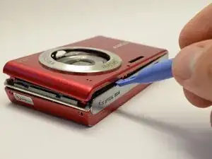
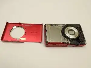
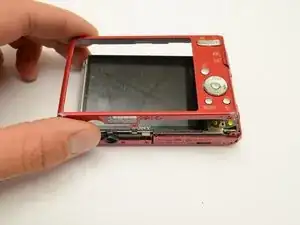
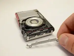
    • Once the outer casings have been removed, the silver side trim should come loose from the camera.

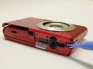
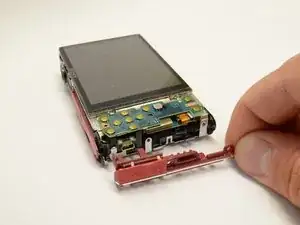
    • Place the camera with the lens facing down. Use the plastic opening tool to pry off the side panel with the USB plug.

    • Note: If you wish to remove the top cover, see the LCD Display Replacement to remove the LCD screen before continuing to Step 5

  5. bti6XaqPImhSQSeX
    bti6XaqPImhSQSeX
    UyaKDDF6I6HElT1N
    n3smEJmqWqvpChbM
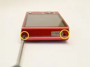
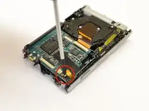
    • Place the camera with the lens facing down. Use the phillips head screwdriver to remove the silver screw in the corner near the photo capture button.

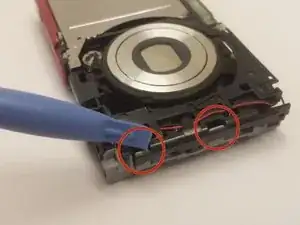
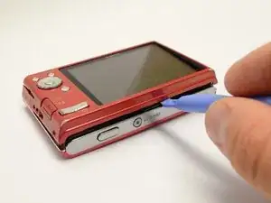
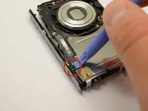
    • Flip the camera over. Use the plastic opening tool to detach the black clip near the capture button.

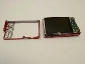
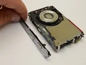
    • Grasp the top cover and gently remove it from the camera body.

  6. EPFSJe5FWCPc3F2q
    EPFSJe5FWCPc3F2q
    vVy2g2jlEkWwaSxq
    JlCVVWViAyFE6MCw
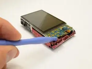
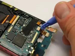
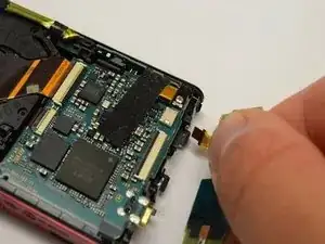
    • Gently pry the tab holding the ribbon cable connecting the cameras control board to the camera sensor and battery housing.

    • The camera control board is now removed and can be replaced if faulty.

  7. yrgdhnawFItDVLRk
    yrgdhnawFItDVLRk
    RmvWbdmbWyvkLt3q
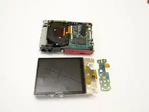
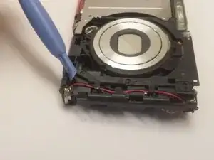
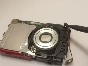
    • With the camera laying with the lens up, use the plastic pry tool to gently push the two gray tabs located on the edge of the camera face.

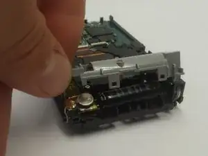
    • Flip the camera over. With the camera laying face down, grab the gray cover on the side and gently remove it.

    • Be careful not to handle the capacitor at the contacts, or you may get shocked.

  8. sSmLnZyTVKSNKRhw
    sSmLnZyTVKSNKRhw
    qpuLAlu6KZ5lFWkm
    1OH2U3Aw5TJkYKOY
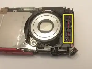
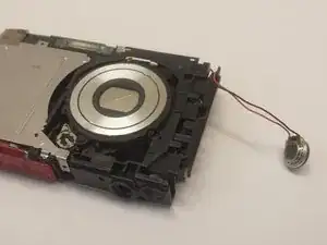
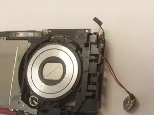
    • Use the plastic pry tool to push the small round silver speaker out through the slot on the side.

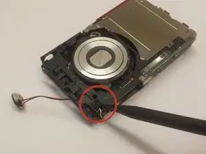
    • With your hand, grab the speaker and gently remove the wires from the retaining clips.

  9. aLaFXnLroqIIWIUV
    aLaFXnLroqIIWIUV
    yVOX2SoKaXkqI6r3
    ataQZ22ZKTaLJhHf
    • With the camera laying with the lens up, use the spudger tool to grab the small square piece of rubber and gently pull it out.

    • Note: Be careful not to pull on it too hard, the wires connected to it are short and could easily be pulled out or damaged.

  10. 3yVy1FDHKwH3QylE
    3yVy1FDHKwH3QylE
    YLEPnXuQR4Qy43fQ
    arKM5TSQv63vUJCg
    • Caution: Be careful not to touch the capacitor wires as you work. If possible, use a capacitor discharge probe to safely rid the capacitors of dangerous charges.

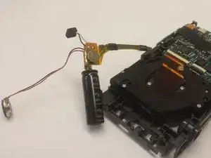
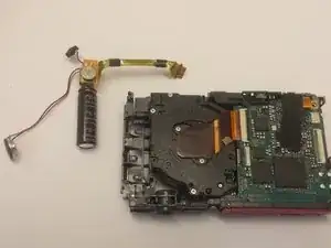
    • Place the camera facing with the lens down. Grab the black capacitor and gently remove the assembly from the holder.

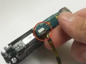
    • Locate the ribbon cable connecting the capacitor to the top of the camera. Grasp the ribbon cable with your fingers, and gently pull outwards.

    • Note: You may need to gently wiggle the connector back and forth to work it out. Do not use much force to pull the cable out. If it is too difficult to remove, use the plastic pry tool to pull the connector by the tabs on the side.

    • Now the flash capacitor assembly is disconnected from the camera and can be removed.

Conclusion

To reassemble your device, follow these instructions in reverse order.

Sam Lewis

Member since: 18/10/13

538 Reputation

0 comments