Introduction
-
-
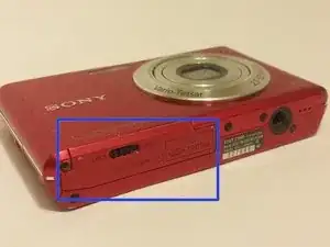
Hold the camera with the bottom edge facing you and find the battery cover on the bottom left of the camera.
-
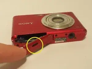
Use the black latch to unhook the cover by sliding it to the "Open" position.
-
The battery cover should easily open by gently lifting it away from the camera.
-
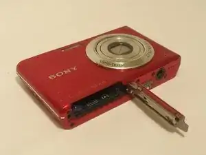
The battery compartment is now open and the battery can be replaced.
-
-
-
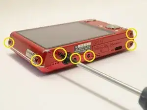
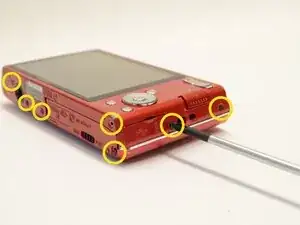
Begin by placing the camera flat against a surface and remove the nine (9) black screws. Each screw is of the same length and can be used interchangeably
-
-
-
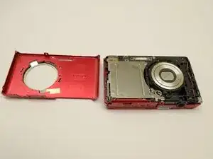
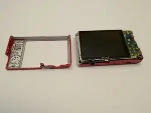
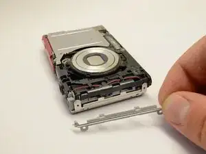
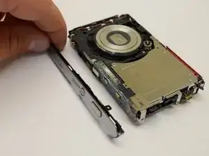
Once the outer casings have been removed, the silver side trim should come loose from the camera.
-
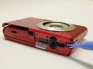
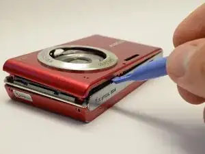
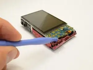
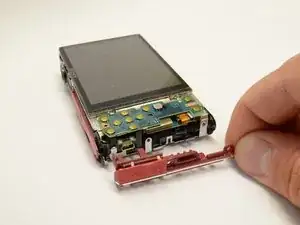
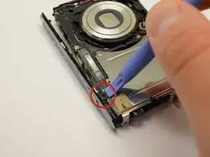
Place the camera with the lens facing down. Use the plastic opening tool to pry off the side panel with the USB plug.
-
-
-
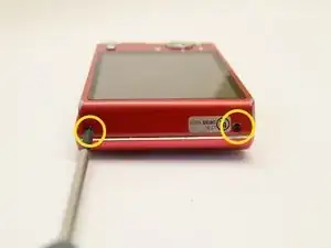
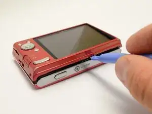
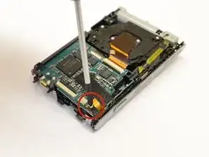
Place the camera with the lens facing down. Use the phillips head screwdriver to remove the silver screw in the corner near the photo capture button.
-
Flip the camera over. Use the plastic opening tool to detach the black clip near the capture button.
-
Grasp the top cover and gently remove it from the camera body.
-
-
-
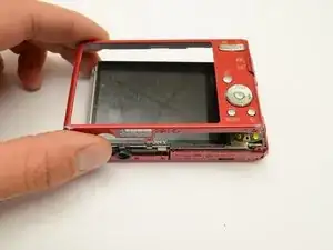
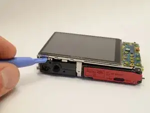
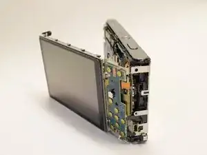
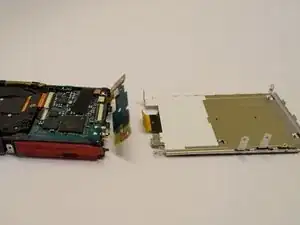
After the outer casing is removed, lay the device display side up
-
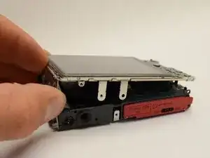
Gently pry the LCD screen from the body of the camera.
-
-
-
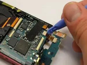
Flip the LCD Assembly around the edge of the camera
-
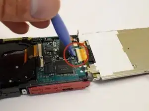
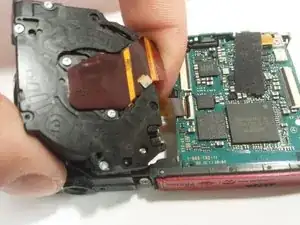
Use the plastic opening tool to gently pry up the black tab locking the large ribbon cable to the battery housing.
-
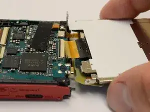
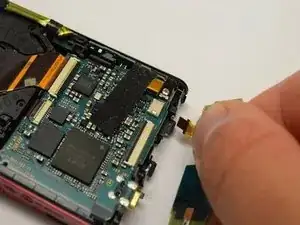
Grasp the LCD display with your fingers and gently pull the large ribbon cable out of the connector.
-
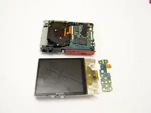
The LCD display is now detached from the camera.
-
-
-
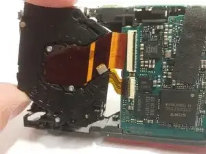
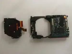
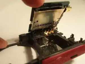
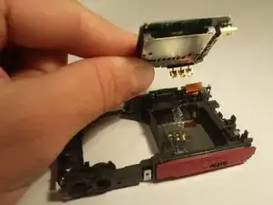
Gently pry the tab holding the ribbon cable connecting the cameras control board to the camera sensor and battery housing.
-
The camera control board is now removed and can be replaced if faulty.
-
-
-
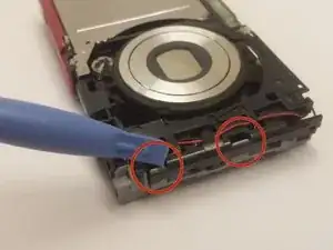
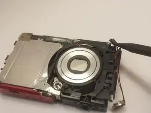
With the camera laying with the lens up, use the plastic pry tool to gently push the two gray tabs located on the edge of the camera face.
-
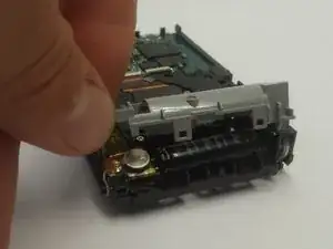
Flip the camera over. With the camera laying face down, grab the gray cover on the side and gently remove it.
-
-
-
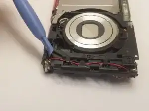
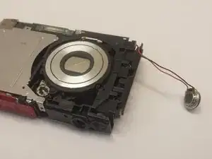
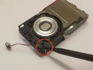
Use the plastic pry tool to push the small round silver speaker out through the slot on the side.
-
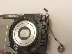
With your hand, grab the speaker and gently remove the wires from the retaining clips.
-
-
-
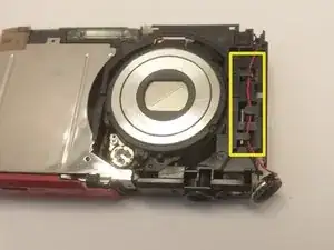
With the camera laying with the lens up, use the spudger tool to grab the small square piece of rubber and gently pull it out.
-
-
-
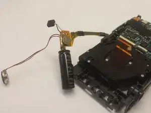
Place the camera facing with the lens down. Grab the black capacitor and gently remove the assembly from the holder.
-
Locate the ribbon cable connecting the capacitor to the top of the camera. Grasp the ribbon cable with your fingers, and gently pull outwards.
-
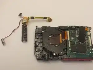
Now the flash capacitor assembly is disconnected from the camera and can be removed.
-
-
-
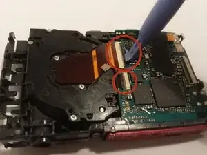
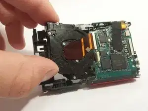
With the camera lying with the lens facing down, use the plastic pry tool to gently lift the black tabs on the two ribbon cable attachments.
-
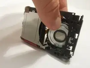
Grasp the black plastic lens assembly with your fingers, and gently pull it out of the camera body from the side of the LCD display.
-
-
-
With the lens assembly pulled out of the camera, grasp one of the ribbon cables and gently pull it out of the connector. Then grab the other ribbon cable and remove it.
-
Now the lens assembly is detached from the camera and can be removed and replaced if necessary.
-
-
-
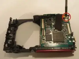
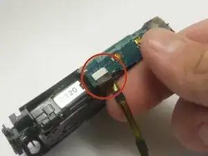
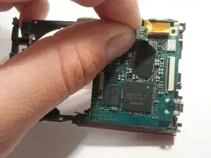
Place the camera so that the lens would be facing down. Use the phillips head screwdriver to remove the small silver screw in the top right corner.
-
Gently peel back the black adhesive tape from the top edge.
-
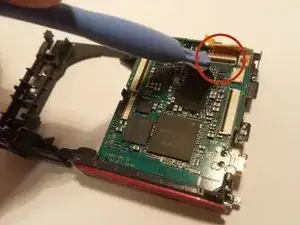
Use the plastic opening tool to pry the black locking tab up.
-
Gently remove the ribbon cable from the connector
-
-
-
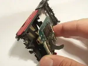
Grasp the circuit board with your fingers and gently pull it out of the camera.
-
This will require you to work it back and forth because it is tightly secured to the camera.
-
Be careful not to damage the battery terminal connectors, they may be holding the circuit board to the battery compartment.
-
The circuit board is now removed and can be replaced if necessary.
-
To reassemble your device, follow these instructions in reverse order.