Introduction

This is a prerequisite-only guide! This guide is part of another procedure and is not meant to be used alone.

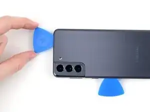
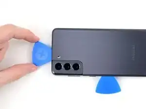
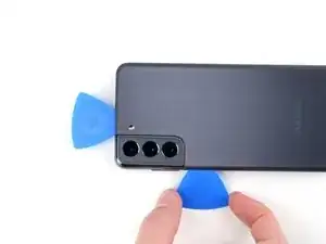
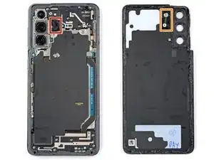
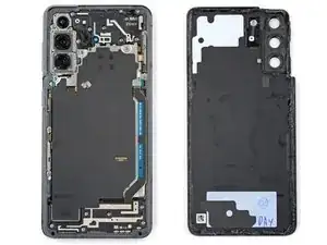
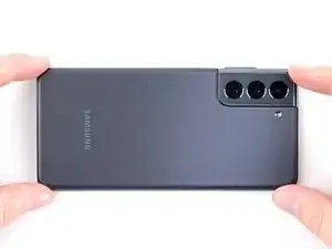
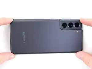
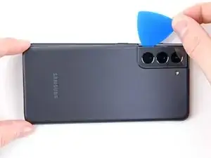
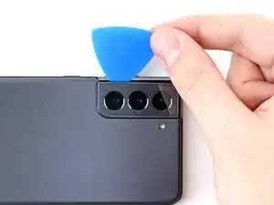
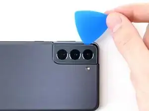
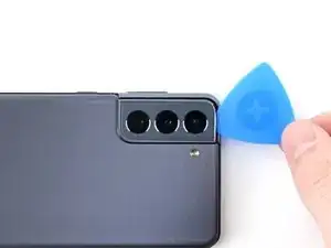
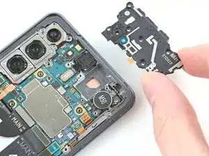
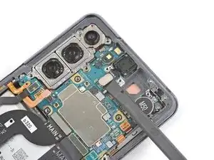
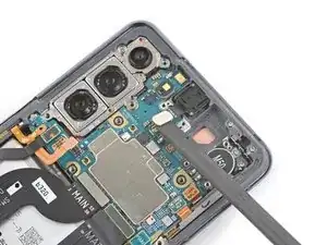
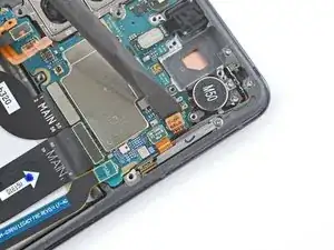
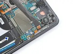
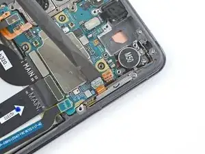
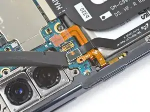
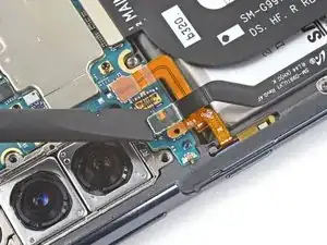
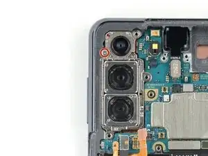
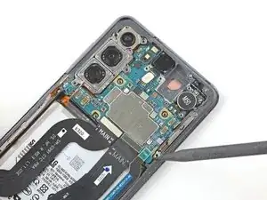
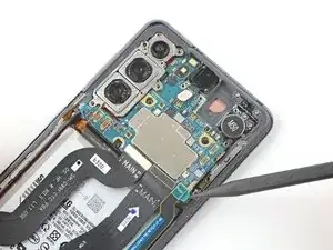
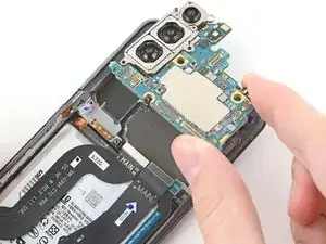
Use this guide to remove or replace the motherboard and rear camera in your Samsung Galaxy S21.

For your safety, discharge the battery below 25% before disassembling your phone. This reduces the risk of a dangerous thermal event if the battery is accidentally damaged during the repair. If your battery is swollen, take appropriate precautions.

  1. nFXwaFaNmphSXM4t
    • Completely power off your phone before you begin.

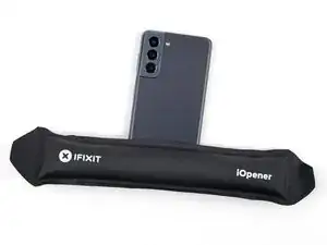
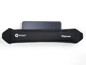
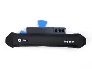
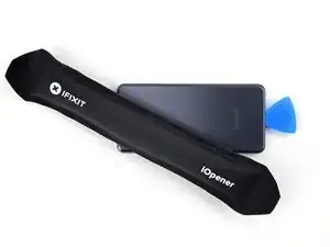
    • Heat an iOpener and apply it to the back cover's bottom edge for two minutes.

    • A hair dryer, heat gun, or hot plate may also be used, but be careful not to overheat the phone—the display, internal battery, and plastic back cover are both susceptible to heat damage.

  2. 3HEYc1oK4HRprxY6
    3HEYc1oK4HRprxY6
    2GieDujEOQUti1Wv
    hXjLkRWSXY1aOCco
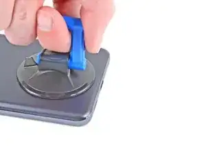
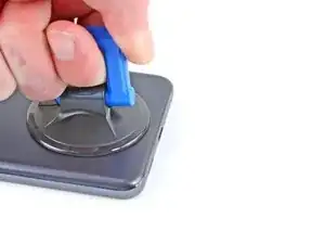
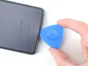
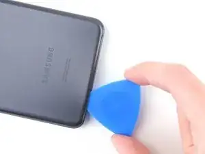
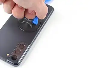
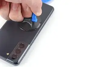
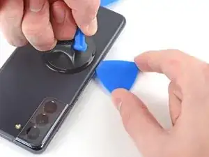
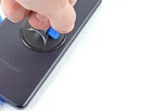
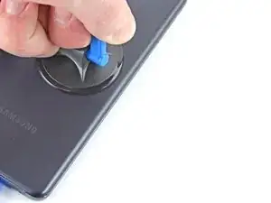
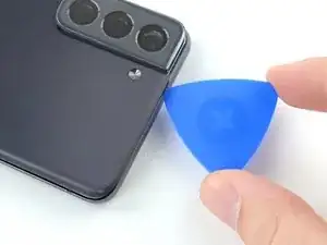
    • Apply a suction cup to the back of the phone, as close to the center of the bottom edge as possible.

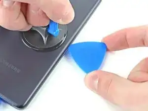
    • Pull up on the suction cup with strong, steady force to create a gap between the back cover and the frame.

    • Depending on the age of your phone, this may be difficult. If you're having trouble, apply more heat to the edge and try again.

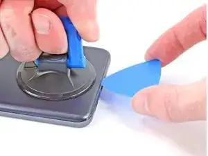
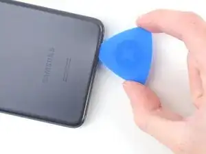
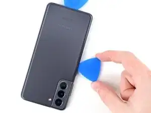
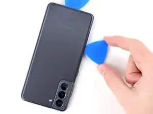
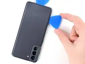
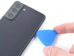
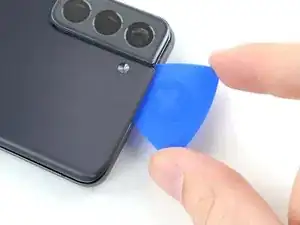
    • Insert an opening pick into the gap.

    • Only insert the pick up to 5 mm, as you may damage internal components if you go further.

  3. eSduLU2NfKm5mcW5
    eSduLU2NfKm5mcW5
    wrAv5TZidVqUXqNH
    5VYSUeqLouCTbYdK
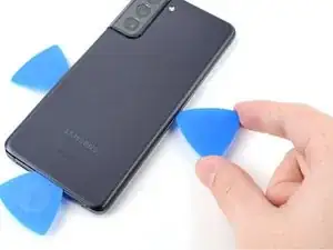
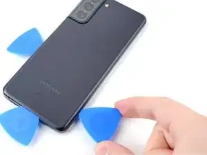
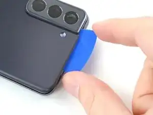
    • Slide the pick back and forth along the bottom edge to slice through the adhesive.

    • Leave the pick in to prevent the adhesive from resealing.

  4. wUBmrWpdNOiMxiMi
    • Apply a heated iOpener to the back cover's left edge for two minutes.

  5. drbwaJMQcy5LmBen
    drbwaJMQcy5LmBen
    6F2VZEgyllV6SkSQ
    mbsZSOOFPJFEkdlv
    • Apply a suction cup to the back of the phone, as close to the center of the left edge as possible.

    • Pull up on the suction cup with strong, steady force to create a gap between the back cover and the frame.

    • Insert an opening pick into the gap.

    • Only insert the pick up to 5 mm, as you may damage internal components if you go further.

  6. J52uxDgX5JdefBrK
    J52uxDgX5JdefBrK
    CxDr4oJhj2oOCHPP
    nmnxq2dqk1AJf6KA
    • Slide an opening pick along the left edge towards the bottom left corner to cut the adhesive.

    • Don't cut past where the camera shell meets the back cover, as you risk cracking the plastic.

    • Leave the pick in to prevent the adhesive from resealing.

  7. lNtArsLZJBwK4Dpr
    • Apply a heated iOpener to the back cover's right edge for two minutes.

  8. fwGZtZArqhxyYGdI
    fwGZtZArqhxyYGdI
    VnD5USQS2hhHVsjL
    4ogHxpLMbEB5WM5d
    • Apply a suction cup to the back of the phone, as close to the center of the right edge as possible.

    • Pull up on the suction cup with strong, steady force to create a gap between the back cover and the frame.

    • Insert an opening pick into the gap.

    • Only insert the pick up to 3 mm, as you may damage the secondary interconnect cable, which runs parallel to the right edge.

  9. ipA4RYIlhHZDOLnK
    ipA4RYIlhHZDOLnK
    IlXgeK2WTMURH13O
    RkM3IRKht5eDKiXk
    • Slide an opening pick back and forth along the back cover's right edge to cut the adhesive.

    • Leave the pick in to prevent the adhesive from resealing.

  10. XqHUCB1T4RlY6H3H
    XqHUCB1T4RlY6H3H
    RJWYIyPhHnNvOiDD
    AyX4MNCgTWb2YI1O
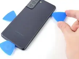
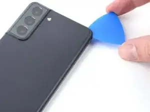
    • Rotate the right-edge opening pick around the top-right corner of the phone.

    • Only insert the pick up to 5 mm, as you may damage internal components if you go further.

    • This procedure can be applied to each corner, except the top-left where the rear-facing camera is located.

  11. waHFYqLJyXMZxTqZ
    waHFYqLJyXMZxTqZ
    YJsWWdGUaeVSRMP2
    qkTTKlDuKNOvnWWT
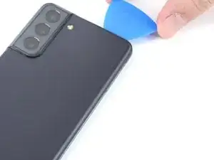
    • Slide the top-most opening pick as close to the camera shell as possible.

    • Repeat for the left-edge pick.

  12. dVF2ePIfdntWVqC5
    dVF2ePIfdntWVqC5
    NOGCo2PABOXYHEsJ
    4UgybM4vGEfqTyuA
    • Heat an iOpener and apply it to the camera shell for two minutes.

    • As you wait for the adhesive to loosen, note the following:

    • There's additional adhesive to the right of the camera that you need to cut through.

    • There's a plate on the back cover surrounding the phone's flash that the pick can get stuck on:

    • Angle the pick downward to avoid any damage.

  13. 5ILUDkyEXY5JvKec
    5ILUDkyEXY5JvKec
    OCt4NmSjWjXINZ4E
    pnRWaXgCuuPtFQ3h
    • Rotate the back cover counterclockwise to create a gap between the camera shell and the frame.

    • Only insert the pick up to 5 mm to avoid scratching the camera.

    • Insert an opening pick in the gap.

    • If this method doesn't work, move to the next step for an alternative method; otherwise, skip the next step.

    The whole topic of the camera shell and adhesive is confusing. It's not immediately clear if the camera bezel is a separate piece. I suggest redoing this section a bit and combining it with the alternate method (which really isn't an alternate at all). The square of adhesive in the flash area needs to be called out in the same step as the camera shell/bezel. This topic is simpler than it appears in this manual. I expected all sorts of adhesive to be on the camera frame when I got the cover off, but that wasn't the case. Make sure to indicate the camera shell/bezel is integrated with the case.

    Don Riggs -

    Hi Don.

    Thank you for the feedback! I have consolidated some of the steps to make it simpler.

    Alex Diaz-Kokaisl -

  14. uHTSlM15CStwfi3u
    uHTSlM15CStwfi3u
    vwoHH5T1lycFaAEo
    as1dMAJhHvYvERhd
    • Slide an opening pick between the camera shell and the frame to cut the adhesive.

    • There's a significant amount of adhesive securing the frame to the camera shell, so multiple rounds of heating may be needed.

  15. FUlfcAd2hZFwWpYT
    FUlfcAd2hZFwWpYT
    mqdfpMiFs1bR1fal
    XddibPk2qkNWsuKe
    • Line up the opening pick's tip with your phone's flash

    • Insert the pick slowly, making sure to avoid the flash's plate.

    • The plate's resistance can feel similar to adhesive. Angle the pick downward to keep the pick from sliding into the plate.

    • Slice the adhesive to the right of the camera.

  16. DOKRRGuNQn5UTQDN
    DOKRRGuNQn5UTQDN
    OlUeiF1Z2HpuCrea
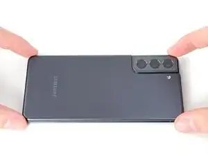
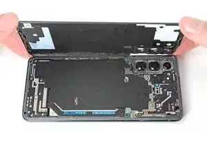
    • Remove the back cover.

    • If your back cover is still sticking to the frame, slide the pick around the edges of the phone until the back cover completely separates.

    • During reassembly:

    • This is a good point to power on your phone and test all functions before sealing it up. Be sure to power your phone back down completely before you continue working.

    • Remove any adhesive chunks with a pair of tweezers or your fingers. Apply heat if you're having trouble separating the adhesive.

    • If you're using Samsung custom-cut adhesives, follow this guide.

    • If you're using double-sided tape, follow this guide.

    Do NOT clean the inside of the back cover with alcohol. I was trying to wipe away some adhesive residue (not even necessary, just get the chunks out), and I got the alcohol on this delicate gasket that's around the clear plastic lens covers in back cover. I wish they had made these windows glass, because they are junk (another topic). The alcohol caused about 1/3 of the gasket to disintegrate immediately. This didn't make me happy, because I didn't want to wait for a new gasket (if they are even available). I improvised, but I hope no more of the gasket flakes off and gets on the camera lenses.

    Don Riggs -

  17. GQaY1KNEnkuAIUID
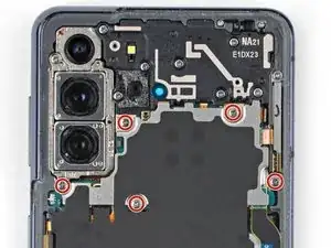
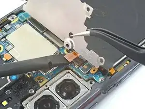
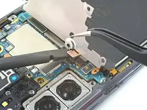
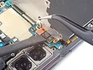
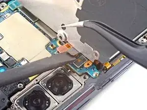
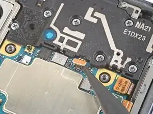
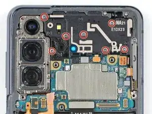
    • Use a Phillips screwdriver to remove the five 4 mm-long screws securing the motherboard bracket to the frame.

    • Throughout this repair, keep track of each screw, and make sure it goes back exactly where it came from.

  18. UXEgWpMEKVHnCxlj
    UXEgWpMEKVHnCxlj
    bVjCPmQROVtZ2Ga1
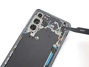
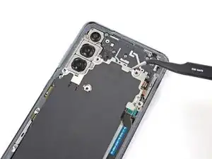
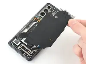
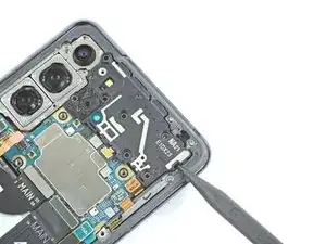
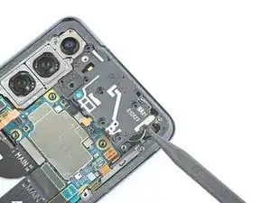
    • Use a pair of tweezers to gently pull up and unclip the motherboard bracket from the frame.

    • Do not completely remove the bracket yet, as it's still attached to the wireless charging coil.

  19. edof4wwKdY36hHow
    edof4wwKdY36hHow
    oqkuadwCE6yyULIl
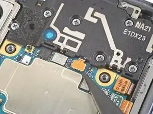
    • While using tweezers, or your fingers, to hold the motherboard bracket out of the way, use a spudger to pry up the battery press connector.

    • Take care to pry only under the edge of the connector to prevent damaging the socket itself and surrounding components.

    • To re-attach press connectors like this one, carefully align and press down on one side until it clicks into place, then repeat on the other side. Do not press down on the middle. If the connector is misaligned, the pins can bend, causing permanent damage.

  20. Do3elGKPvNa2ETpk
    Do3elGKPvNa2ETpk
    JUwBRXaRPRQ5qXdt
    • While still holding the motherboard bracket out of the way, use a spudger to pry up and disconnect the wireless charging coil's press connector.

  21. ZDlOBgBMQgSBW3Kn
    ZDlOBgBMQgSBW3Kn
    1gfUYUXLoojg3iWT
    pWDOlGRodVmS4WiG
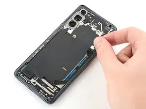
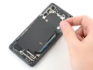
    • The wireless charging coil is secured to the phone with light adhesive.

    • Use your fingers to gently peel the wireless charging coil away from the phone.

    • During reassembly, refasten the motherboard bracket screws first to properly align the charging coil into place, then firmly press the rest of the coil down to adhere it.

  22. Mpv4fu6athpTxV22
    Mpv4fu6athpTxV22
    RPYmKbdnZIRJ2eKZ
    • Use the point of a spudger to pry up and disconnect the earpiece speaker cable's press connector.

  23. VBuHuOEgjFH6CCTQ
    • Use a Phillips screwdriver to remove the seven 4 mm screws securing the earpiece speaker to the motherboard.

  24. VrCZKfSKFQGolGQT
    VrCZKfSKFQGolGQT
    JrSNfAOmrOehFYvu
    GPAd4AqnaThnoc55
    • Insert the point of a spudger into the gap between the right-most edge of the earpiece speaker and the phone.

    • Use the spudger to pry up and release the clips holding the earpiece speaker in place.

    • Use tweezers, or your fingers, to remove the earpiece speaker.

  25. AAmDORJxKLKZfcKo
    AAmDORJxKLKZfcKo
    YxjQg1FTPkHraSR5
    • Use the flat end of a spudger to pry up and disconnect the front camera's press connector.

  26. oIRAXZM3KkfV4MdX
    oIRAXZM3KkfV4MdX
    QAC3IJ4i4yykQXAX
    FZfCQBNjfAqQebJZ
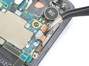
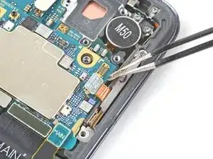
    • Use a spudger to pry up and disconnect the orange press connector adjacent to the 5G antenna cable's press connector.

    • Repeat for the green 5G antenna cable's press connector.

  27. CTBZTboAmlOdcaa1
    CTBZTboAmlOdcaa1
    FarKG4ClmbAnNkkd
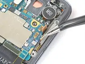
    • Use a spudger to pry up and disconnect the 5G antenna cable's press connector.

    My phone doesn't have one? I double checked the model before I took it apart and that's correct and everything else is correct in the guide so far, but here I have the two orange connectors with no black 5G antenna cable.

    Meg Mitchell -

    Hi Meg.

    Great catch! Some S21 models don't have these antennas; they are limited to Verizon carriers. I will update the introductions to explain this.

    Alex Diaz-Kokaisl -

    Thanks Alex! I had some water damage in my phone that was causing the cameras to fog up so I was able to remove them, dry out the cameras, put them back in and everything works great. Really loving these little ifixit tools.

    Meg Mitchell -

  28. 4qh5xsbjQGpJMxLw
    4qh5xsbjQGpJMxLw
    DZKxsusDhtI2rZA6
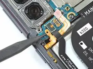
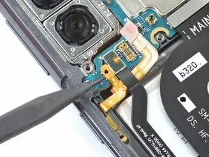
    • Use the point of a spudger to pry up and disconnect the power button cable's press connector.

  29. PGAJkmjOejwZiDPN
    PGAJkmjOejwZiDPN
    CLntf1uhxNOCXXYD
    • Use the flat end of a spudger to pry up and disconnect the display cable's press connector.

  30. KRdC2rtrSWGIBBZe
    KRdC2rtrSWGIBBZe
    F2CnpTDWnYQ1AgKN
    4YqYX5QFCZMGYIBh
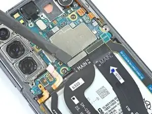
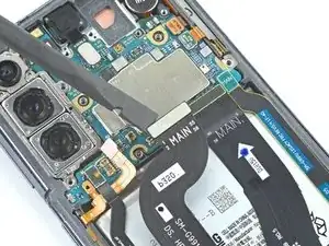
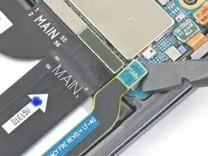
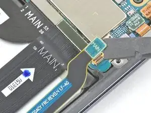
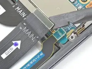
    • Use a spudger to pry up and disconnect the secondary interconnect cable's press connector.

    • Repeat for the main interconnect cable's press connector.

  31. 3ihux3SOgvBZghBd
    • Use a spudger, or your fingers, to bend the power button cable away from the phone.

    • Repeat for the left-edge 5G antenna cable.

    • Avoid folding or sharply bending the cables while repositioning them; doing so could tear the cables.

  32. KOAHUBISBORLnQCw
    KOAHUBISBORLnQCw
    VRgylIqHxlqTwOqR
    txkb1QNGjpNUBpUa
    • Use tweezers, or your fingers, to bend the orange 5G antenna cable away from the phone.

    • Repeat for the green 5G antenna cable.

    • Avoid folding or sharply bending the cables while repositioning them; doing so could tear the cables.

  33. VarKvGslocxeTyOe
    • Use a Phillips screwdriver to remove the 4 mm screw securing the camera bracket and the motherboard to the frame.

  34. xLkLcxh5EY4bHiUs
    xLkLcxh5EY4bHiUs
    qaaCRRQMCFj4PfUU
    4A3J2eQGLtWZVZYY
    • Insert a spudger between the bottom-right edge of the motherboard assembly and the frame.

    • Pry up with the spudger to release the clips securing the motherboard assembly.

    • Use your fingers to remove the motherboard assembly.

Conclusion

Compare your new replacement part to the original part—you may need to transfer remaining components or remove adhesive backings from the new part before installing.

To reassemble your device, follow the above steps in reverse order.

Take your e-waste to an R2 or e-Stewards certified recycler.

Repair didn’t go as planned? Check out our Answers community for troubleshooting help.
Alex Diaz-Kokaisl

Member since: 16/01/22

117875 Reputation

0 comments