Introduction

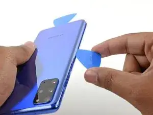
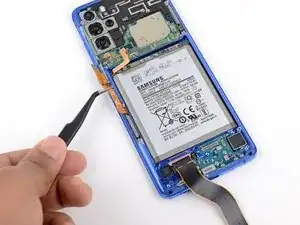
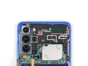
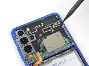
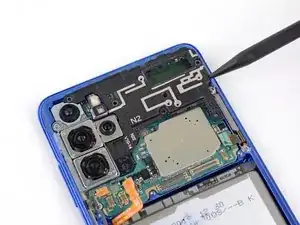
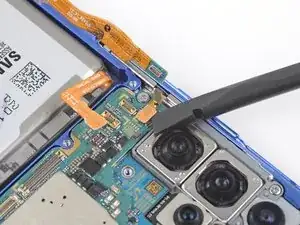
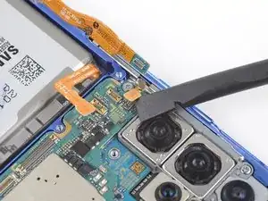
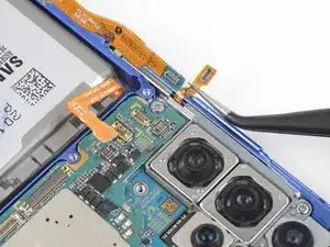
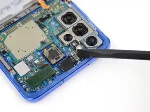
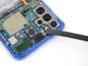
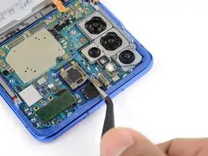
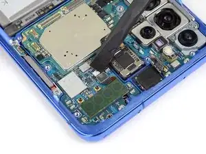
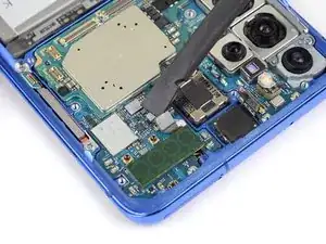
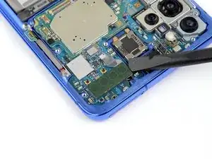
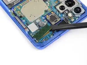
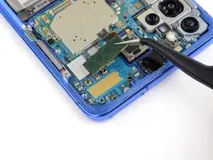
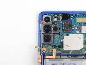
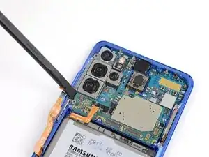
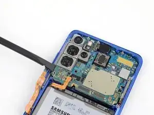
Follow this guide to remove and replace the earpiece speaker in the Galaxy S20 Plus.

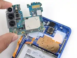
While it is not completely necessary to remove the motherboard in order to remove the earpiece speaker, the repair is made much easier with the motherboard out of the way.

  1. vQpvnPIOawBX4MI3
    vQpvnPIOawBX4MI3
    VCAWWTfELiK2dWh4
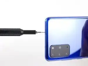
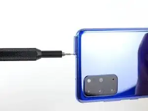
    • Insert a SIM card eject tool, bit, or a straightened paperclip into the hole on the SIM tray, located at the top edge of the phone next to the plastic antenna band.

    • If you inserted the tool into the other hole, don't worry—the microphone and the ingress gasket are mounted out of harm's way.

    • Press in firmly to eject the tray.

  2. PUF4JmMZIr6DDSuO
    PUF4JmMZIr6DDSuO
    kTGGABXFKp5RGVXm
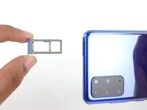
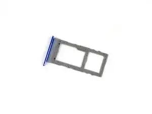
    • Remove the SIM card tray.

    • The SIM card will fall out of the tray easily.

    • When you reinsert the SIM card, ensure that it is in the proper orientation relative to the tray.

    • A thin rubber gasket around the SIM tray provides water and dust protection. If this gasket is damaged or missing, replace the gasket or the entire SIM tray to protect your phone's internal components.

  3. RGQTOGPFnsCcpEgk
    • Unplug and power off your phone before you begin.

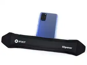
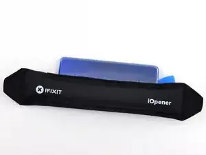
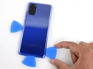
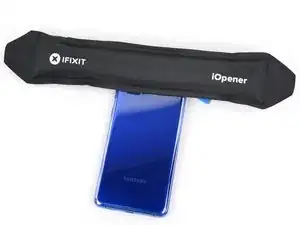
    • Heat an iOpener and apply it to the back cover's bottom edge for two minutes.

    • A hair dryer, heat gun, or hot plate may also be used, but be careful not to overheat the phone—the display and internal battery are both susceptible to heat damage.

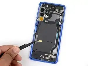
  4. LNX1YnZ2IliLlHlO
    LNX1YnZ2IliLlHlO
    NK1k56TvaO3arMlF
    OHRyEEwPE1TloEgT
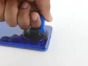
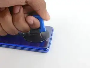
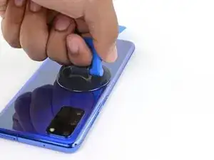
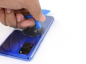
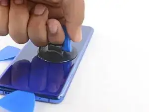
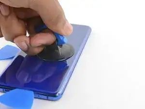
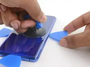
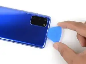
    • Apply a suction cup to the back of the phone, as close to the center of the bottom edge as possible.

    • If your display is badly cracked, covering it with a layer of clear packing tape may allow the suction cup to adhere. Alternatively, very strong tape may be used instead of the suction cup. If all else fails, you can superglue the suction cup to the broken glass.

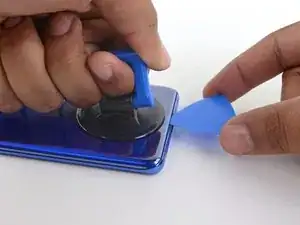
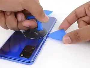
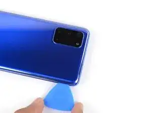
    • Pull on the suction cup with strong, steady force to create a gap between the back cover and the frame.

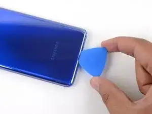
    • Insert the point of an opening pick into the gap.

    • Due to tight tolerances, this may take multiple attempts of reheating with the iOpener and separating with the suction cup before you get it right.

    • If you are having trouble creating a gap, apply more heat to the edge and try again.

    • Do not apply excessive force with the pick, or you risk cracking the back cover glass.

  5. cmUEJSd3tWMfNlMf
    cmUEJSd3tWMfNlMf
    GC6tjtUNyER5FM5X
    nveoYwTlBQJBG3WA
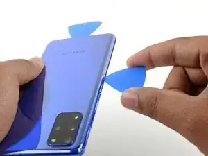
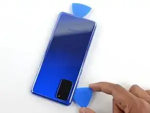
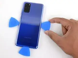
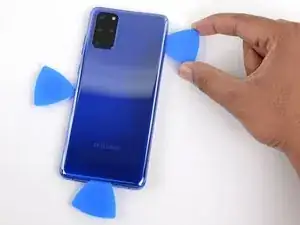
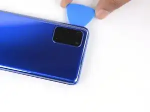
    • Slide the pick back and forth along the bottom edge to slice through the adhesive.

    • Do not attempt to cut the adhesive near the corners of the phone where the glass is curved or you risk cracking the glass panel.

    • Leave your opening pick in the seam to prevent the adhesive from resealing.

  6. SRM1Z1BRPRQjubxm
    • Apply a heated iOpener to the left edge of the back cover for two minutes.

  7. pMMSKMYxb2AJVc2a
    pMMSKMYxb2AJVc2a
    taCXdaZXYSAEPhf4
    PRX2kcGRSBYPxbDc
    • Apply a suction cup to the back of the phone, as close to the center of the left edge as possible.

    • Pull on the suction cup with strong, steady force to create a gap between the back cover and the frame.

    • Insert the point of an opening pick into the gap.

    • As the glass on this edge is curved, you won't be able to insert this pick very far. As long as the very tip of the pick is underneath the glass's edge, you will be able to proceed.

    • Due to tight tolerances, this may take multiple attempts.

    • If you are having trouble creating a gap, apply more heat to the edge and try again.

    • You can try also applying a few drops of high concentration (over 90%) isopropyl alcohol into the seam to help loosen the adhesive.

    • Do not apply excessive force with the pick, or you risk cracking the back cover glass.

  8. rl1TPKFFLTe24JTW
    rl1TPKFFLTe24JTW
    GgyxAsq11wCjVJqC
    • Once the pick is underneath the glass's edge, tilt it downward and insert it further to fully separate the back cover's adhesive.

  9. BKeryiSHoPnSdnwf
    BKeryiSHoPnSdnwf
    RlRwU2uKc2UwlTMH
    iQ2WGblFVsI6p2kM
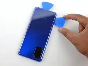
    • Slide the pick all along the left edge of the phone to separate the back cover's adhesive.

    • Take care when sliding across the ridge in the frame surrounding the volume and power buttons—the cutout in the glass may make it more prone to cracking.

    • Leave your pick under the left edge of the glass to prevent the adhesive from resealing.

  10. 3FUrgRNIX6wRxNxr
    • Apply a heated iOpener to the right edge of the back cover for two minutes.

    • A hair dryer, heat gun, or hot plate may also be used, but be careful not to overheat the phone—the display and internal battery are both susceptible to heat damage.

  11. VUKQi4L22oB3KE5b
    VUKQi4L22oB3KE5b
    PHpklysCpbt6YssP
    icUPtvXaLG5UqQjg
    • Apply a suction cup to the back of the phone, as close to the center of the right edge as possible.

    • Pull on the suction cup with strong, steady force to create a gap between the back cover and the frame.

    • Insert the point of an opening pick into the gap.

    • Like with the previous edge, you will need to tilt the opening pick downward to fully insert it underneath the back cover.

  12. GJ2twTm252UuIcWR
    GJ2twTm252UuIcWR
    SFUTnesVLmRnKgEA
    C3UDnoguKYtgJBYS
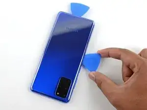
    • Slide the pick all along the right edge of the phone to separate the back cover's adhesive.

    • Leave your pick under the right edge of the glass near the top of the device to prevent the adhesive from resealing.

    • As you do this, the back cover may release one or both of the other picks and allow them to fall free. If this occurs, set the pick(s) aside as the bottom edge shouldn't reseal from this point onward.

  13. BloAMPsqEwokmpic
    • Apply a heated iOpener to the top edge of the back cover for two minutes.

  14. wYGGjntSLQfttLTZ
    wYGGjntSLQfttLTZ
    xJLySSjP4EFoWOMC
    1tbIvvJA2iiQTqQx
    • The glass near the corners of the back cover is curved and very susceptible to cracking. Be gentle during this step to prevent damaging your back cover.

    • Gradually slide the pick from the right edge of the device around the top right corner.

    • Continue slicing along the top edge all the way around to the left edge to fully separate the back cover adhesive.

    • If the slicing becomes difficult at any point, stop and reapply heat before continuing.

  15. kUKESuMLUNGpErlI
    kUKESuMLUNGpErlI
    RaxbFjK3C4uAxuu6
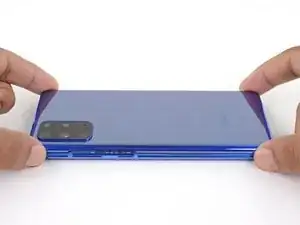
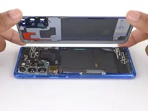
    • Lift the back cover slowly. Use opening picks to slice any remaining adhesive.

    • Remove the back cover.

    • During reassembly:

    • This is a good point to power on your phone and test all functions before sealing it up. Be sure to power your phone back down completely before you continue working.

    • Remove any adhesive chunks with a pair of tweezers or your fingers. Apply heat if you're having trouble separating the adhesive.

    • If you're using Samsung custom-cut adhesives, follow this guide.

    • If you're using double-sided tape, follow this guide.

  16. pSgHMBAO5pZWB6p5
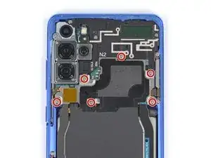
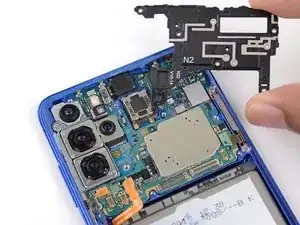
    • Use a Phillips #00 screwdriver to remove the six 4 mm-long screws securing the motherboard bracket.

    • Throughout this repair, keep track of each screw and make sure it goes back exactly where it came from.

  17. 5fj1SRDy34NXggh5
    5fj1SRDy34NXggh5
    iu1ovGxPgxdXwAoh
    UKjNF5JJVPEA2KfQ
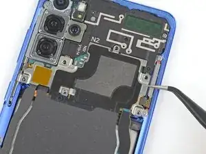
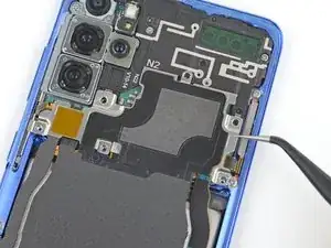
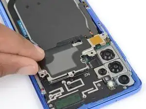
    • Use a pair of tweezers to gently pull up and unclip the motherboard bracket from the plastic midframe.

    • Do not completely remove the bracket yet, as its still attached to the wireless charging coil.

  18. TRapJLQDy5hh4cHs
    TRapJLQDy5hh4cHs
    nwMo66buUSJTt3so
    wvoOQGHxgSKkCYcM
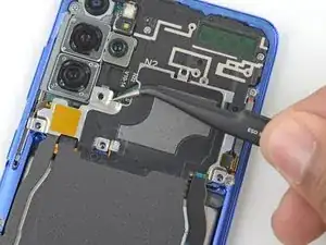
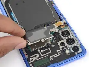
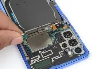
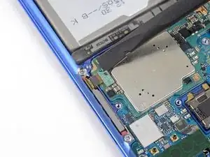
    • Gently tilt up the motherboard bracket so the orange battery connector is accessible.

  19. xd3nWqAkOk6WLteB
    xd3nWqAkOk6WLteB
    Ghb5rA4dojgIHPou
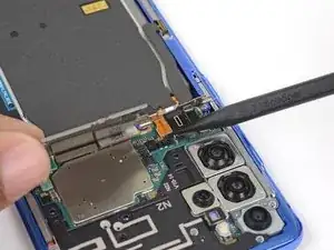
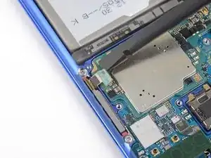
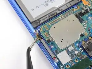
    • Use a spudger to pry up and disconnect the battery connector.

    • When you disconnect connectors like these, be careful not to dislodge the small surface-mounted components surrounding the socket.

  20. 3EOMhiUSjSkkj5Bv
    3EOMhiUSjSkkj5Bv
    n6Mg4EPW3q6rPPi2
    • Use a spudger to pry up and disconnect the wireless charging coil connector.

  21. qqcGQPSmVcwTGfjU
    qqcGQPSmVcwTGfjU
    o2sdviXhltVSn4Nk
    mQhZKISXBCRDRtLX
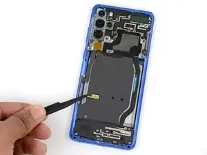
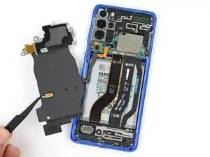
    • Use a pair of tweezers to gently peel the wireless charging coil away from the device.

    • Remove the wireless charging coil.

    • During reassembly, first reconnect the charging coil and battery connectors and refasten the motherboard bracket screws to properly align everything into place, then firmly press the coil pad down to adhere it.

  22. 2jZSEV51wXXcBi4w
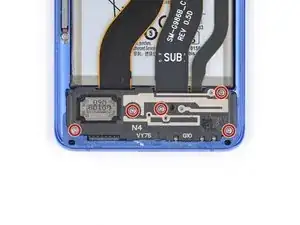
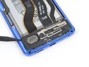
    • Use a Phillips #00 screwdriver to remove the five 4 mm-long screws securing the loudspeaker and lower midframe.

  23. KvdIZVACy1ZnHTus
    KvdIZVACy1ZnHTus
    YRVQlbGJ5JvFKqY1
    AxIAbVWNEOfYrQB6
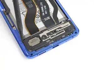
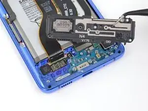
    • Insert the point of a spudger or a pair of tweezers into the notch in the top left corner of the midframe and pry up to release the clips holding it in place.

    • Remove the loudspeaker and lower midframe.

  24. ucaEsKjAAvEi12Zx
    ucaEsKjAAvEi12Zx
    ZDybGDuJO4Xpgl4P
    HotXpdaRsJs2tupk
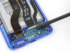
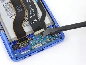
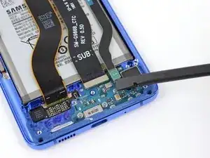
    • Use a spudger to pry up and disconnect the main and auxiliary flex cables from the daughterboard near the bottom of the device.

    • To re-attach press connectors like this one, carefully align and press down on one side until it clicks into place, then repeat on the other side. Do not press down on the middle. If the connector is misaligned, the pins can bend, causing permanent damage.

  25. TkQhLclC3vpDWhYY
    TkQhLclC3vpDWhYY
    4MbtxCjJhYbO4XPS
    ssICDjOKjiA5HCIN
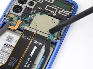
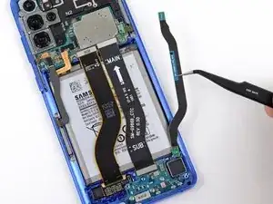
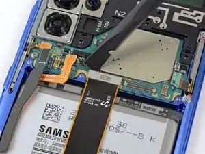
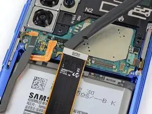
    • Use a spudger to pry up and disconnect the main and auxiliary flex cables from the motherboard.

  26. 3PTbVOft4dUGhJO6
    3PTbVOft4dUGhJO6
    5shNGCgMpZJugQxF
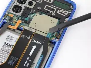
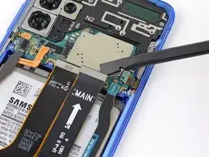
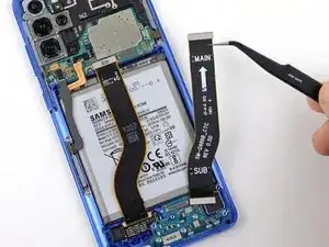
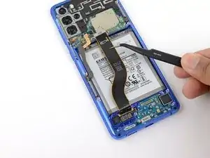
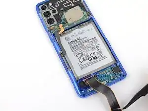
    • Gently peel up and remove the main and auxiliary flex cables.

  27. GRK1OhmRUQNAwkdA
    GRK1OhmRUQNAwkdA
    Bo2AhlEKnFHQho3P
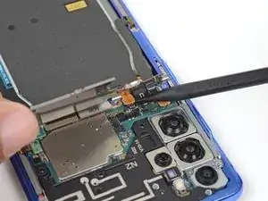
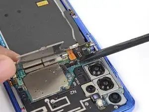
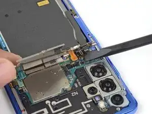
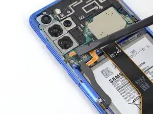
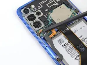
    • Pry up and disconnect the left 5G antenna cable from the motherboard.

  28. BlHlmMuUC6aIW3i3
    BlHlmMuUC6aIW3i3
    a2q5A21IBYuRQUyX
    • Use a spudger to pry up and disconnect the main display flex cable from the motherboard.

  29. GkHPveZVBSn62QOc
    GkHPveZVBSn62QOc
    U1VniJ4mCqlPA4am
    pGBP1ULxcKYtxgku
    • Gently peel up and bend the display and left 5G antenna flex cables out of the way of the motherboard and battery.

  30. NBokFaWA4ImPOYCp
    • Use a Phillips #00 screwdriver to remove the three 4 mm-long screws securing the upper midframe.

  31. MHkBD6ZRk34bCKTS
    MHkBD6ZRk34bCKTS
    djhlQyjBMIIlTbJ4
    ZwlNs2PeFQnMtELo
    • Insert the point of a spudger into the notch on the right side of the upper midframe and pry up to release the clips holding it into place.

    • Remove the upper midframe.

  32. VyFJAApcUgO6VxXm
    VyFJAApcUgO6VxXm
    vbpTa6elfZffIhA6
    2rVnpbZgkCWesLSu
    • Use a spudger to pry up and disconnect the right 5G antenna flex cable from the motherboard.

    • Use a pair of tweezers to bend the cable out of the way of the motherboard.

  33. sgi2KT3kXvj2kGZy
    sgi2KT3kXvj2kGZy
    dTPTdXJQwliPqRBV
    5tQPLf4ShJx2ybmc
    • Pry up and disconnect the side button flex cable from the motherboard.

    • Bend the cable out of the way of the motherboard.

  34. 1xSSVwBFqUmqvXbG
    1xSSVwBFqUmqvXbG
    tuQbkpOMxvc4GOrB
    RPHILWvOShmU3BBI
    • Pry up and disconnect the front facing camera flex cable from the motherboard.

    • Bend the cable out of the way of the motherboard.

  35. FkdVWxdo5CfbISHg
    FkdVWxdo5CfbISHg
    KsjmU2Efiuk2Icnp
    • Pry up and disconnect the upper 5G antenna cable from the motherboard.

  36. qMG3FQBsxODfHKKa
    qMG3FQBsxODfHKKa
    niQOFmVPiGo34xXH
    4vZh6DG5AGtbJfUb
    • Use the flat end of a spudger to pry up the corner of the 5G millimeter wave antenna module.

    • The module is secured with a bit of adhesive, but should release easily.

    • Remove the 5G antenna module.

    • During reassembly, reconnect the 5G antenna connector first to properly align it into place, then firmly press the rest of the antenna module down to adhere it.

  37. fjq4j6ufjKHfMjts
    • Use a Phillips #00 screwdriver to remove the two screws securing the motherboard and camera assembly.

    • One 4 mm-long screw

    • One 3.4 mm-long screw

  38. u3dVQHIL2TCSIHjT
    u3dVQHIL2TCSIHjT
    LuBbCuBTZBAQBKsQ
    y2jkDDX4JvZyOiW6
    • Insert the flat end of a spudger into the bottom left corner of the motherboard assembly and pry up to release it from the phone body.

    • Remove the motherboard assembly.

  39. dLxEDXyMEgaxexHm
    dLxEDXyMEgaxexHm
    uQeR3ZCRhsid3GcU
    5myGSbUCodORJlB3
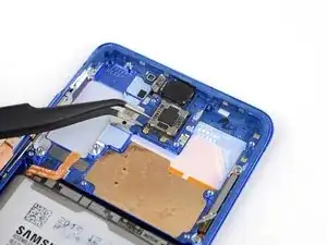
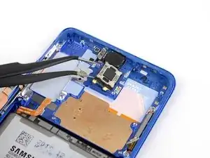
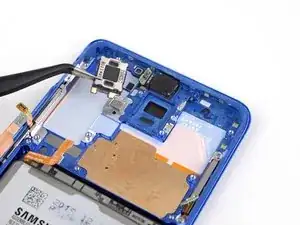
    • Insert one point of a pair of tweezers into the notch at bottom left corner of the earpiece speaker.

    • The earpiece speaker sits in a deep recess and is secured with adhesive. If you have trouble getting under it, apply a few drops of high concentration (over 90%) isopropyl alcohol to help soften the adhesive.

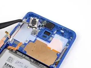
    • Pry up to release the adhesive and remove the earpiece speaker.

    • It is possible to reuse the speaker adhesive when installing a replacement speaker, but if you need to replace the adhesive, you can do so with a pre-cut adhesive sheet.

Conclusion

Compare your new replacement part to the original part—you may need to transfer remaining components or remove adhesive backings from the new part before installing.

To reassemble your device, follow the above steps in reverse order.

After you've completed the repair, follow this guide to test your repair.

Take your e-waste to an R2 or e-Stewards certified recycler.

Repair didn’t go as planned? Check out our Answers community for troubleshooting help.

Tarun Thiruma

Member since: 20/11/19

35226 Reputation

One comment

I replaced the earspeaker but it still doesnt work. I cant see any connector for this. Any tips?
Evan Thomas-Broughton -