Introduction
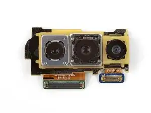
Follow this guide to remove and replace the rear-facing camera module for the Galaxy S10+. The module includes all three rear-facing cameras, as well as the frame that holds them.
This procedure requires removing the motherboard. The most difficult part is separating the glass back cover from the phone.
-
-
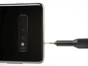
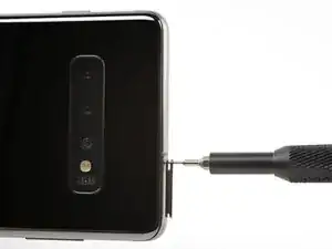
Insert a SIM card eject tool, bit, or a straightened paperclip into the hole on the SIM tray, located at the top edge of the phone next to the plastic antenna band.
-
Press firmly to eject the tray.
-
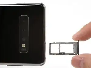
Remove the SIM card tray.
-
-
-
Unplug and power off your phone before you begin.
-
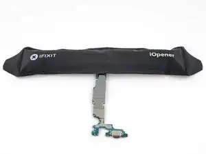
Heat an iOpener and apply it to the back cover's right edge for two minutes.
-
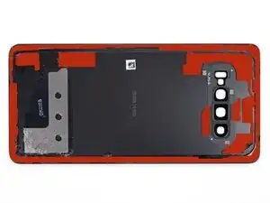
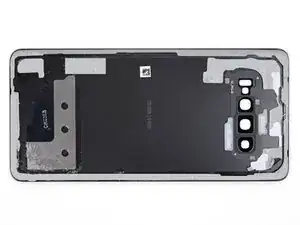
As you wait, take a look at the image of the removed back cover and take note of where the adhesive is located.
-
-
-
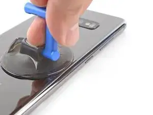
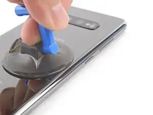
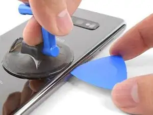
Apply a suction cup to the back of the phone, as close to the center of the right edge as possible (where the adhesive is narrowest).
-
Pull on the suction cup with strong, steady force to create a gap between the back cover and the frame.
-
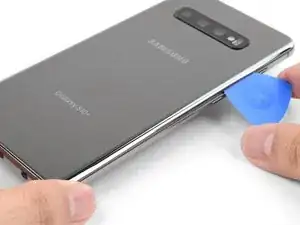
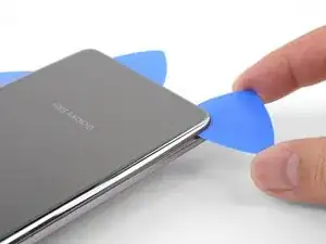
Insert the point of an opening pick into the gap.
-
If you are having trouble creating a gap, your best bet is to apply more heat to the edge and try the previous step again.
-
You can try applying a few drops of high concentration (over 90%) isopropyl alcohol into the seam to help loosen the adhesive.
-
-
-
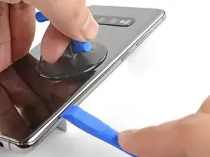
Rest the heated right edge of the phone on something that is about 0.5 inches (13 mm) thick. This angles the phone for the opening tool.
-
Brace the left edge of the phone with your fingers so that the phone won't slide. Pull on the suction cup with firm pressure.
-
Press the edge of an opening tool into the seam between the back cover and the frame.
-
Slide the opening tool back and forth along the seam a few times.
-
-
-
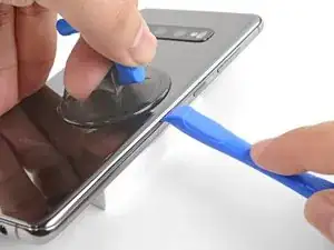
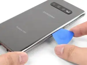
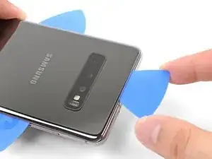
Slide the opening pick along the edge of the phone, slicing through the adhesive.
-
Leave a pick in the seam to prevent the adhesive from re-sealing.
-
-
-
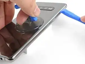
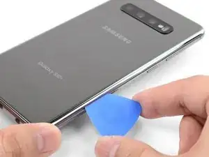
Insert an opening pick into the right edge near the bottom right corner.
-
Carefully slide the pick around the corner. Continue cutting along the bottom edge and around the bottom left corner.
-
Leave an opening pick in the seam to prevent the adhesive from re-sealing.
-
-
-
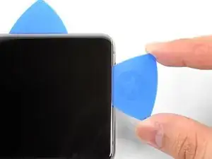
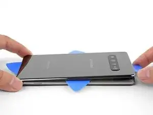
Once you have sliced around the phone, twist an opening pick in one of the edges to help separate the back cover from the frame.
-
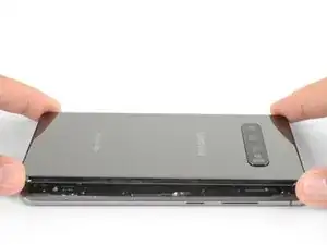
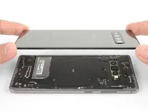
Lift the back cover slowly. Use opening picks to slice any remaining adhesive.
-
Remove the back cover.
-
-
-
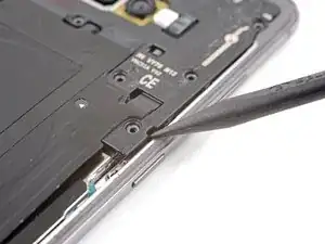
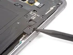
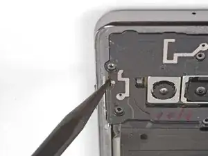
Insert the point of a spudger into the notch on the right edge of the midframe, near the Bixby button.
-
Pry up to loosen the midframe from the phone.
-
-
-
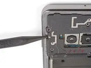
Insert the point of a spudger into the notch on the left edge of the phone, located near the power button.
-
Pry up to loosen the midframe from the phone.
-
-
-
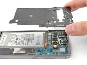
Lift the midframe from the top corners and remove it from the phone.
-
Align the midframe's top edge to the phone and lay the frame down on the phone.
-
Use fingers to apply pressure along the midframe perimeter to snap the midframe clips back into place. The edges should sit flush against the phone edge.
-
-
-
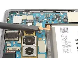
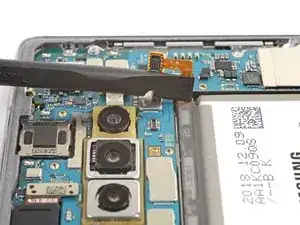
Insert the flat end of a spudger underneath the battery connector, which is attached to the motherboard below the rear-facing camera.
-
Pry upwards to disconnect the connector from its socket.
-
Gently push the battery's flex cable away from the motherboard socket to prevent accidental contact.
-
-
-
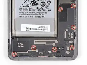
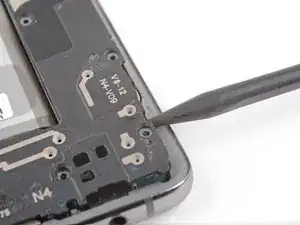
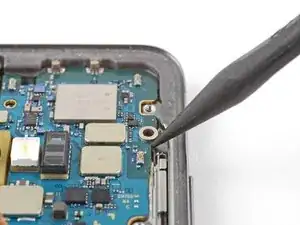
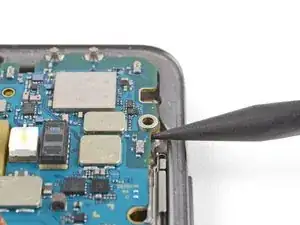
Insert the point of a spudger in the notch near the bottom right corner of the lower midframe. It is marked by a small triangle.
-
Pry up to release the midframe from the phone.
-
-
-
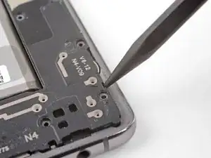
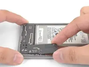
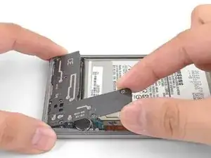
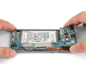
Grasp the loosened end of the midframe with your fingers and lift upwards slowly.
-
Wiggle the midframe slightly to help release the remaining edge clips.
-
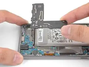
Remove the lower midframe. The loudspeaker is built into the lower midframe.
-
-
-
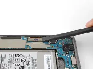
Use the flat end of a spudger to pry up and disconnect the display connector from its motherboard socket, located near the bottom right corner of the phone.
-
-
-
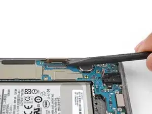
Use the flat end of a spudger to pry up and disconnect the headphone jack's connector from its motherboard socket.
-
-
-
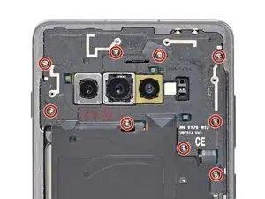
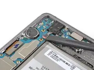
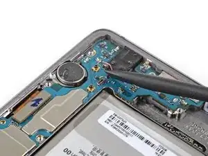
Remove the three Phillips screws securing the motherboard to the phone:
-
One 3.8 mm screw
-
Two 3.7 mm screws
-
-
-
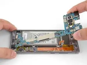
Insert the point of a spudger underneath the right edge of the motherboard, near the volume up button.
-
Pry up gently to loosen the motherboard from its recess.
-
-
-
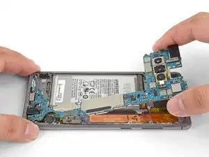
Using your fingers, grasp the motherboard by the top corners.
-
Lift the motherboard edge slightly out of its recess. Be careful not to snag any cables along the way.
-
Pull the motherboard towards the top edge of the phone while wiggling the board slightly. This will loosen the charging port from its socket.
-
Once the charging port is freed from its socket, remove the motherboard.
-
Gently push the motherboard against the bottom edge of the phone until the charging port is completely seated.
-
Lower the motherboard and press into place. Be careful not to trap any cables underneath the motherboard. The board should sit flush against the frame.
-
-
-
Flip the motherboard over.
-
Use the flat end of a spudger to pry up and disconnect the two camera connectors from their sockets on the motherboard.
-
-
-
Heat an iOpener and lay it over the rear-facing camera module for one minute. This helps loosen the adhesive holding the camera module to the motherboard.
-
-
-
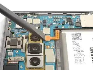
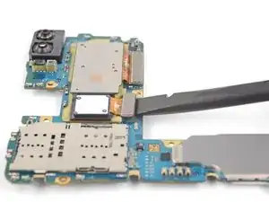
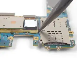
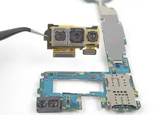
Insert the point of a spudger under the top-left corner of the camera module, where there is a small notch.
-
Pry up to loosen the camera module from the motherboard.
-
-
-
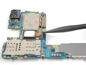
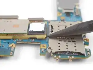
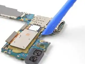
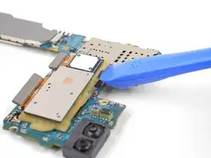
Insert the edge of an opening tool under the loosened corner of the camera module.
-
Pry up to release the camera module from the motherboard.
-
Continue prying around the camera module with the opening tool until the module is freed from the motherboard.
-


To reassemble your device, follow these instructions in reverse order.
After you've completed the repair, follow this guide to test your repair.
Repair didn’t go as planned? Check out our Answers community for troubleshooting help.

So, I have owned multiple phones in my life and some of them had two doors, one for the Sim, one for the SD card. As it was darkish where I was installing the SD & SIM card, this is what I assumed my S10 plus 1tb had, and I poked a paper clip into the microphone hole and when it didn't open I pushed harder not realizing that it was the microphone. Some research that I've done says that the hole is straight and comes to an end and the microphone is 90° to that, so it cannot be poked by the pin, is this true(I hope it is!) ? I don't want to have to take apart my phone if I don't have to, to replace the microphone or God forbid the motherboard to replace one small component. Come on Samsung, is this planned obsolescence?
Lin Car -
Hi Lin,
Good question! I took apart our S10 and that is indeed true! Inserting the SIM eject tool into the top microphone hole shouldn’t damage your microphone, or compromise water resistance.
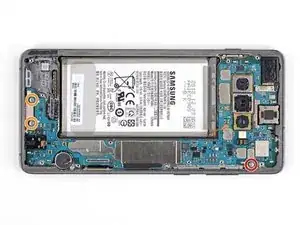
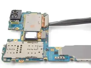
Here is a photo reference. The microphone hole is just an L-shaped tunnel drilled into the frame. At the end of the “L”, it is sealed by a thin waterproof gasket (red circle). The microphone is actually built into the motherboard (orange circle), which is pressed against this gasket. Sound is able to transfer across the thin gasket, but this design also allows it to be waterproof.
I will edit the steps to reflect this information. Thanks for the heads up!
Arthur Shi -