Introduction
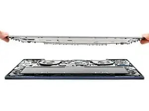
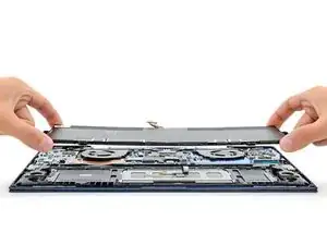
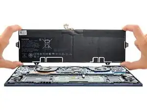
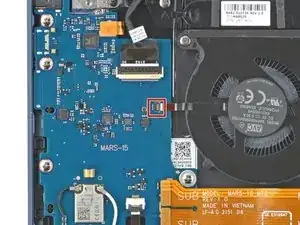
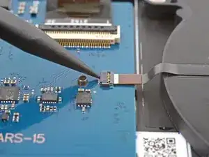
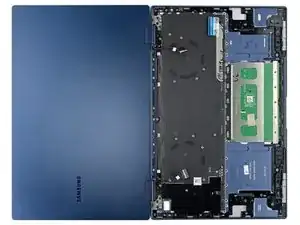
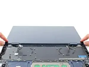
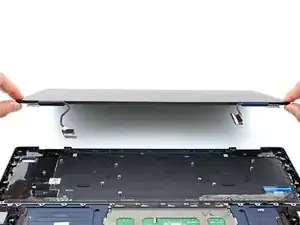
Use this guide to replace the front case on your Galaxy Book Pro 360 15" laptop with a genuine Samsung part.
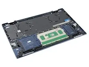
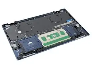
The front case consists of the keyboard and touchpad pre-installed into the frame. Make sure you have the right part before you begin the repair.
Before you begin, refer to the Samsung PC Repair Guide for safety information.
For your safety, discharge the battery below 25% before disassembling your device. This reduces the risk of a thermal event if the battery is accidentally damaged during the repair. If your battery is swollen, take appropriate precautions.
Note: Some photos show the heat sink and primary SSD removed. This is optional, as you don't need to remove the heat sink or the primary SSD to remove the motherboard.
Tools
Parts
-
-
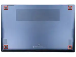
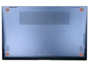
Close the screen and lay your laptop down with the rear case facing up to access the four rubber feet.
-
-
-
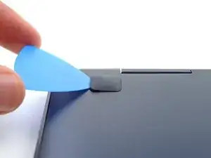
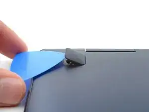
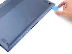
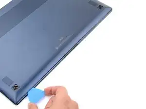
Insert an opening pick between the rear case and the rubber foot.
-
Pry up with the pick and dislodge the foot from the rear case.
-
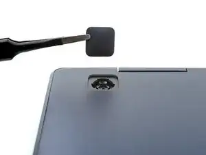
Use tweezers or your fingers to remove the rubber foot.
-
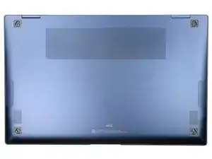
Repeat this process on the remaining rubber feet.
-
-
-
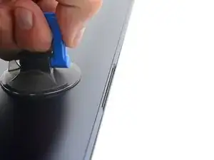
Apply a suction handle to the middle of the rear case's bottom edge, as close to the edge as possible.
-
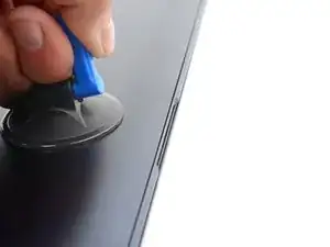
Pull up on the handle with a strong, steady force to create a small gap between the rear case and the frame.
-
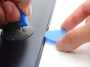
Insert an opening pick into the gap you created.
-
-
-
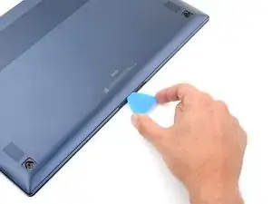
Slide the opening pick along the bottom edge to release the clips securing the rear case.
-
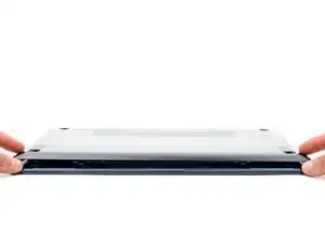
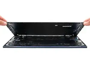
Continue sliding the pick along the perimeter of the laptop until all the clips securing the rear case have been released.
-
-
-
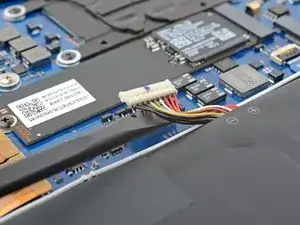
Insert the flat end of a spudger under the battery cables, as close to the connector as possible.
-
Gently pry up and disconnect the battery connector from its socket.
-
-
-
Use the pointed end up a spudger to pry up the locking flap on the left fan cable's ZIF connector.
-
-
-
Grip the left fan cable's pull tab with tweezers and gently pull the cable out of its socket.
-
-
-
Use the flat end of spudger to pry up and disconnect both of the interconnect cable's press connectors from the daughterboard.
-
-
-
Use the pointed end of a spudger to pry up and disconnect the bottom left speaker's connector from the daughterboard.
-
-
-
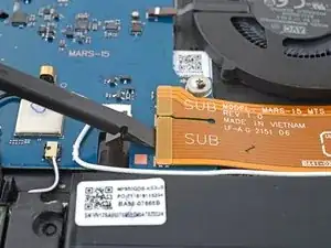
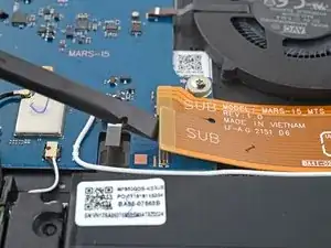
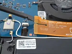
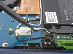
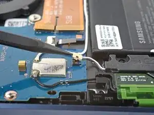
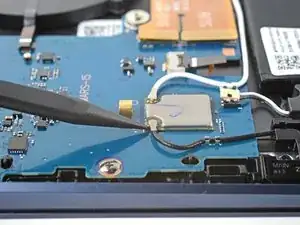
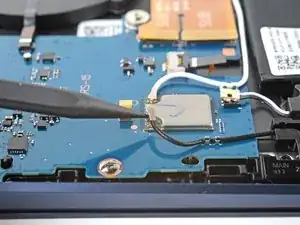
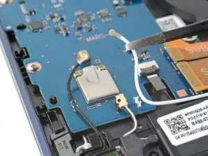
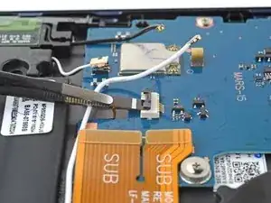
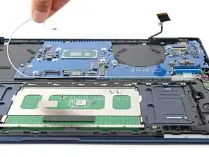
Insert the pointed end of a spudger under the black antenna cable and slide it as close to the connector as possible.
-
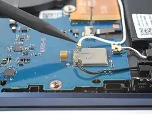
Gently lift straight up to disconnect the antenna.
-
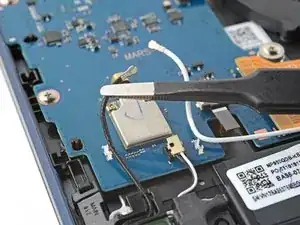
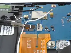
Repeat the disconnection procedure on the white antenna cable.
-
-
-
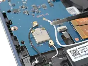
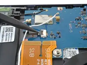
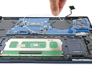
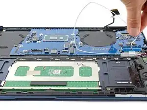
Use tweezers or your fingers to lift the black and white antenna cables out of their clips on the daughterboard.
-
-
-
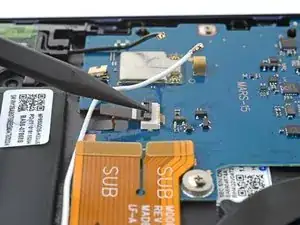
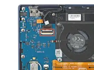
Use the pointed end of a spudger to pry up the locking flap on the backlight cable's connector.
-
-
-
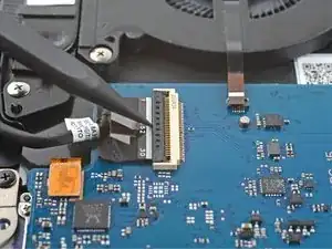
Grip the backlight cable's pull tab with tweezers and gently pull the cable out of its socket.
-
-
-
Grip the left display cable's pull tab with tweezers or your fingers and gently pull the cable out of its socket.
-
-
-
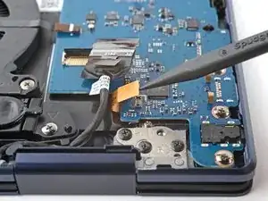
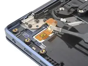
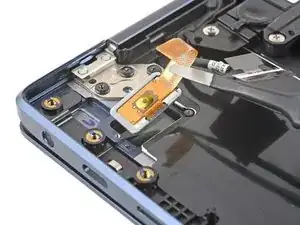
Use the pointed end of a spudger to pry up and disconnect the fingerprint sensor's press connector.
-
-
-
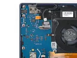
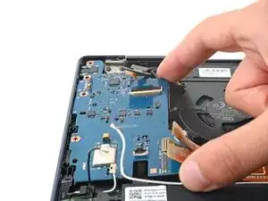
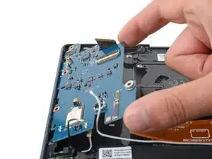
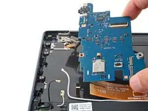
Lift the right side of the daughterboard up and pull towards the center of the laptop to remove it.
-
Move all cables that connect to the daughterboard (display, fingerprint, interconnect, speaker, backlight, and antennas) out of the way so they don't get stuck under the daughterboard when it's reinserted.
-
Reinsert the daughterboard at a downward angle to position the headphone jack, USB-C port, and memory slot back into their recesses.
-
Before securing the daughterboard, make sure the alignment pins on the frame are in their cutouts on the daughterboard.
-
-
-
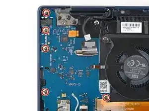
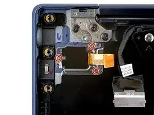
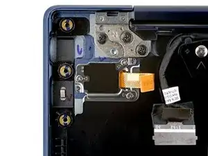
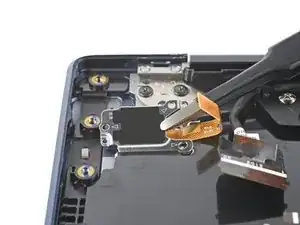
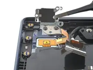
Use a Phillips #00 screwdriver to remove the three 2.5 mm screws securing the fingerprint sensor bracket on the top left corner of the laptop.
-
-
-
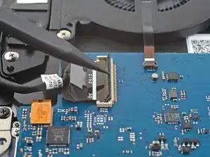
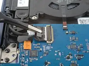
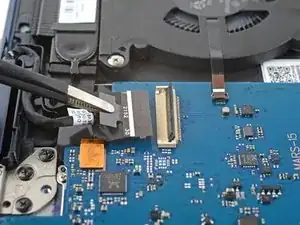
Use the pointed end of a spudger to pry up the locking flap on the right fan cable's ZIF connector.
-
-
-
Grip the right fan cable's pull tab with tweezers and gently pull the cable out of its socket.
-
-
-
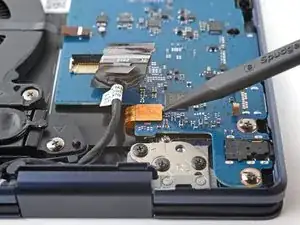
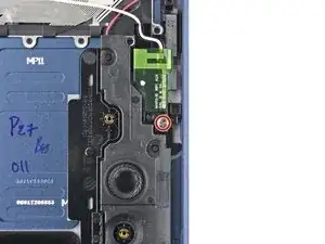
Use the pointed end of a spudger to pry up and disconnect the bottom right speaker's connector from the motherboard.
-
-
-
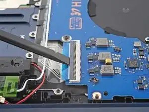
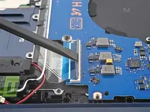
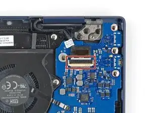
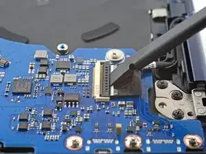
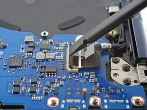
Use the flat end of a spudger to pry up the locking flap on the keyboard cable's ZIF connector.
-
-
-
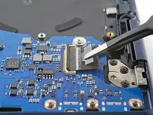
Grip the keyboard cable's pull tab with tweezers or your fingers and gently pull the cable out of its socket.
-
-
-
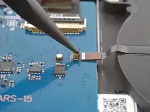
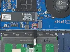
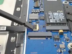
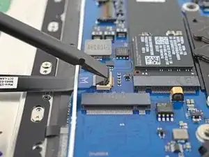
Use the flat end of a spudger to pry up the locking flap on the touchpad's ZIF connector on the motherboard.
-
-
-
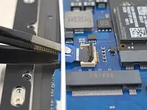
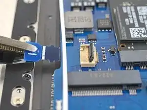
Grip the touchpad cable's pull tab with tweezers and gently pull the cable out of its socket on the motherboard.
-
-
-
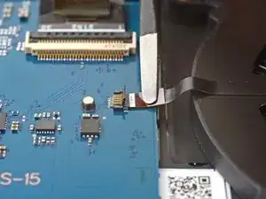
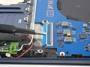
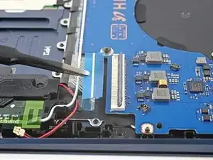
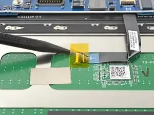
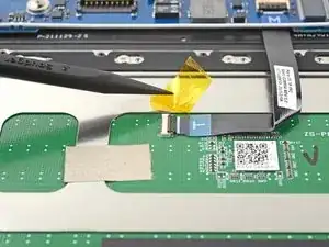
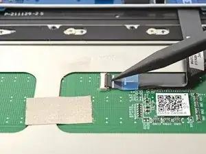
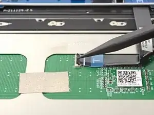
Use your fingers or a spudger to peel up the tape covering the ZIF connector on the touchpad.
-
Remove the tape.
-
-
-
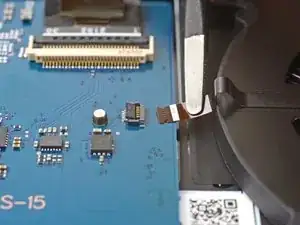
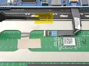
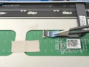
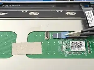
Grip the touchpad cable's pull tab with tweezers and gently pull the cable out of its socket on the touchpad.
-
Remove the touchpad cable.
-
-
-
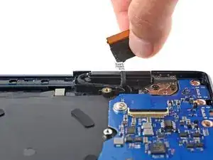
Use the flat end of spudger to pry up the locking flap on the right display cable's ZIF connector.
-
-
-
Grip the right display cable's pull tab with tweezers or your fingers and gently pull the cable out of its socket.
-
-
-
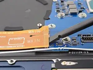
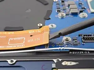
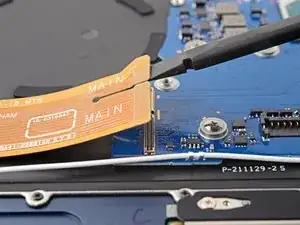
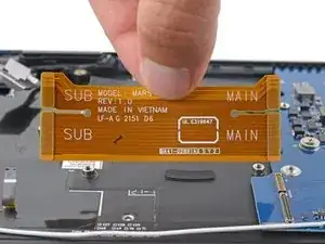
Use the flat end of a spudger to pry up and disconnect both of the interconnect cable's press connectors from the motherboard.
-
-
-
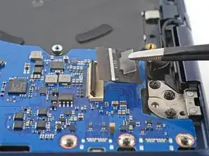
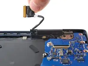
Slowly pull the right display cable out of its recess.
-
Repeat the process on the left display cable.
-
-
-
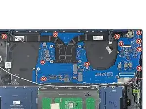
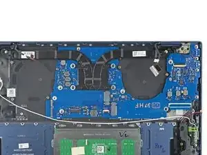
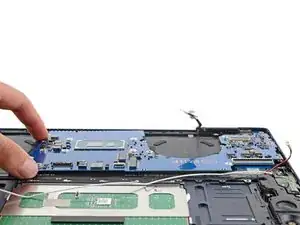
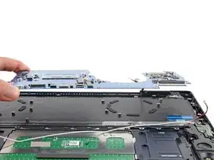
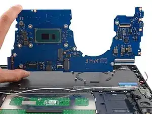
Lift the motherboard straight up and remove it.
-
Move all cables that connect to the motherboard (display, keyboard, speaker, and antenna) out of the way so they don't get stuck under the motherboard when it's reinserted.
-
Make sure the alignment pins on the frame are in their cutouts on the motherboard.
-
Push down on right edge of the motherboard to ensure the USB-C and thunderbolt ports are in their recesses.
-
-
-
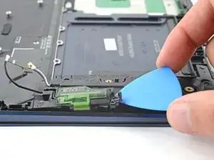
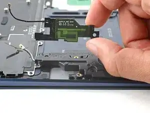
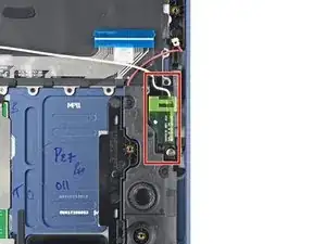
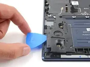
Insert a pick between the left antenna and the bottom left speaker.
-
Pry up with the pick to dislodge the antenna.
-
Remove the antenna from its recess.
-
-
-
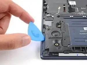
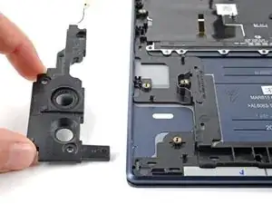
Insert an opening pick between the bottom left speaker's left edge and the frame.
-
Pry up with the opening pick to dislodge the speaker from its recess.
-
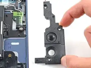
Remove the speaker.
-
-
-
Open the laptop until it's completely flat and lay it down with the display and keyboard facing down.
-
-
-
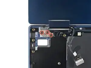
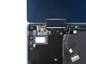
Use a Phillips screwdriver to remove the three 3.5 mm screws securing the left screen hinge.
-
-
-
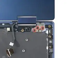
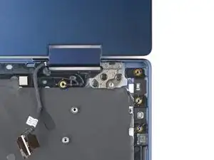
Use a Phillips screwdriver to remove the three 3.5 mm screws securing the right screen hinge.
-
To reassemble your device, follow the instructions in reverse order and perform the opposite actions, e.g., "reattach" instead of "removing." Skip steps that use heating and prying, and pay close attention to the 📌 bullets as you work through the steps.
Take your e-waste to an R2 or e-Stewards certified recycler.
Repair didn’t go as planned? Check out our Answers community for troubleshooting help.
