Introduction

Use this guide to replace the motherboard in your Galaxy Book Pro 15" Laptop.

Before you begin, refer to the Samsung PC Repair Guide for safety information.

For your safety, discharge the battery below 25% before disassembling your device. This reduces the risk of a thermal event if the battery is accidentally damaged during the repair. If your battery is swollen, take appropriate precautions.

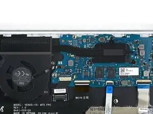
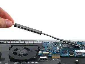
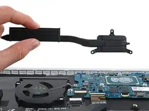
Note: Some photos show the heat sink removed. This is optional, as you don't need to remove the heat sink to remove the motherboard.

  1. HTyDgbiLsTi2wgNM
    HTyDgbiLsTi2wgNM
    5aE4tSww6TYMyDLj
    aRGCQqZ4CrH2GU42
    • Before you begin, power down your laptop and unplug it.

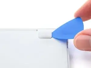
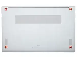
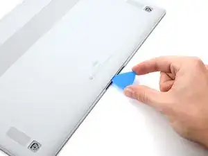
    • There are two kinds of rubber feet along the top and bottom of the rear case. Keep track of their position as you remove them.

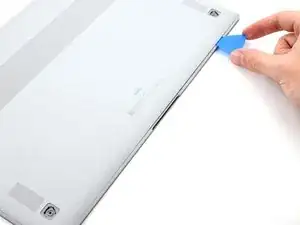
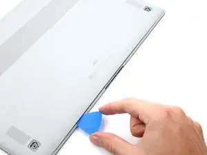
    • Insert an opening pick between the rubber foot and the rear case.

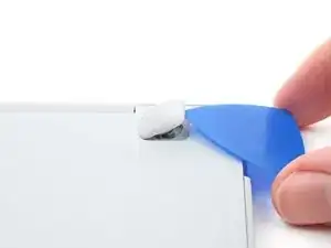
    • Pry up with the opening pick to release the clips securing the foot.

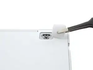
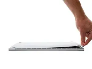
    • Remove the foot.

    • Repeat this procedure for the three remaining feet.

    • During reassembly, press the feet into their correct slot to reinsert them. Mismatched feet won't fit correctly.

  2. jLcXiL1IG2511Ytk
    jLcXiL1IG2511Ytk
    SYUMGMUY1JZ5IDBo
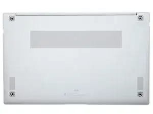
    • Use a Phillips screwdriver to remove the four 4.5 mm-long screws securing the rear case.

    • If you're reassembling with the Samsung Self-Repair kit, be sure to replace the screws with new ones labeled #3313.

  3. dZ15UHrTO2rDYrW4
    dZ15UHrTO2rDYrW4
    utVDfO3wyKKNEnT4
    WEwAYSWxSMHrXvFr
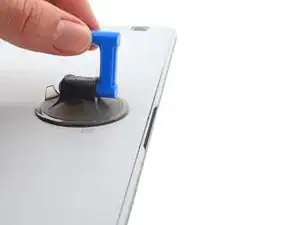
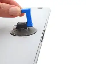
    • Apply a suction cup to the rear case, as close to the center of the bottom edge as possible.

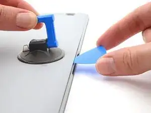
    • Pull up on the suction cup with strong, steady force to create a gap between the rear case and the frame.

    • Insert an opening pick into the gap.

  4. Y2kHCiQhGT6GoIy2
    Y2kHCiQhGT6GoIy2
    tVWucyBNEdF5pSJg
    ukgx5LvtimGNGDOJ
    • Slide the pick along the bottom edge of the rear case to release its plastic clips.

    • Repeat this process for the left and right edges, but stop before reaching the top edge.

  5. KeNh3JiLb2hYVUxH
    KeNh3JiLb2hYVUxH
    4W2uOnJGDkvmPCRj
    wXFQvLmBfuvEFOS6
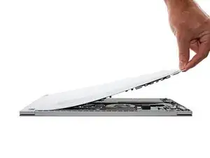
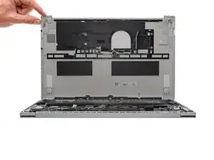
    • The top edge of the rear case is lightly adhered to the frame.

    • Pull the top of the rear case away from the frame to separate the adhesive and release the remaining clips.

    • If you're having trouble separating the adhesive, use an iOpener, hair dryer, or heat gun to soften it.

    • Remove the rear case.

    • During reassembly, perform the following:

    • If you're using a using a genuine Samsung replacement rear case, be sure to peel off any adhesive liners from the rear case before securing the top edge's clips.

    • If you're reusing your rear case, you can use some pre-cut adhesive to re-adhere the top edge if your existing adhesive is no longer sticky.

    • This is a good point to power on your laptop and test all functions before sealing it up. Be sure to power your laptop back down completely before you continue working.

  6. MAARGWltOuSoyXI3
    MAARGWltOuSoyXI3
    ePOaLgYQuOR2Cw1a
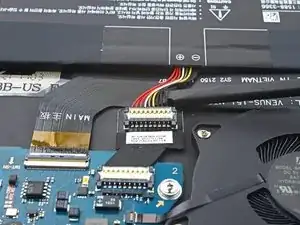
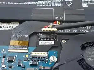
    • Insert a spudger between the frame and the bottom of the battery cable connector.

    • Pry up and disconnect the battery cable connector.

  7. puSRIbygtMPBq2tk
    puSRIbygtMPBq2tk
    Zu1VkDsIVDXXohtW
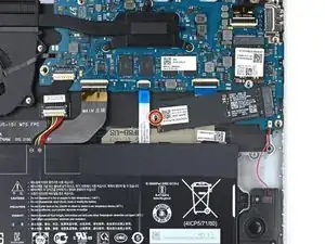
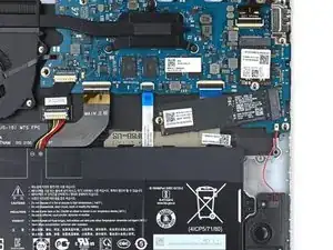
    • If your Galaxy Book doesn't have an M.2 2280 SSD, skip the next two steps.

    • Use a Phillips screwdriver to remove the 3.5 mm-long screw securing the SSD.

  8. SVCg5ec2VKSJ4cvg
    SVCg5ec2VKSJ4cvg
    3RK6NLdYiRIVRp3X
    OaVCsV6g6vONNBbq
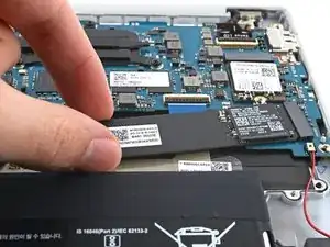
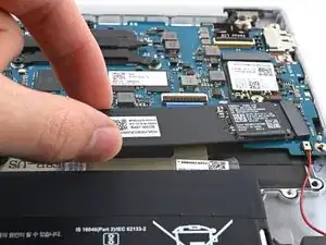
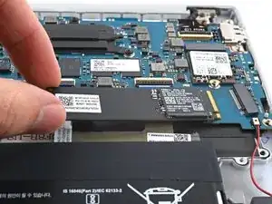
    • Lift the free end of the SSD up slightly and pull the SSD straight out of its socket on the motherboard.

  9. bUFPmDk3JegO4GVS
    bUFPmDk3JegO4GVS
    O4tLZQe2WdlmrCpq
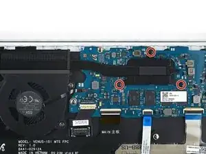
    • Use a Phillips screwdriver to remove the three 3.5 mm-long screws securing the heat sink.

  10. eNTn6CkvGMVgoDLo
    eNTn6CkvGMVgoDLo
    ggyrUNobKJKXrVyT
    ylNRqxFNtxfIHoch
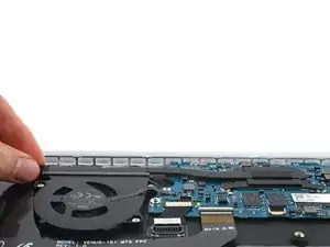
    • Lift the left edge of the heat sink upward to separate the heat sink from the motherboard.

    • You may feel a bit of resistance. This is normal, since the heat sink is slightly bonded to the motherboard with thermal paste.

    • Remove the heat sink.

    • Follow this guide for how to clean and reapply thermal paste.

  11. p56VLNxBSsZWVPqg
    p56VLNxBSsZWVPqg
    skUVis1W2RXRWlDZ
    • Use a Phillips screwdriver to remove the 3.5 mm-long screw securing the SSD.

  12. vVtUGXNUKnfTU1jx
    vVtUGXNUKnfTU1jx
    GvfqXhxcFHEIsFAD
    • Lift the free end of the SSD up slightly and pull the SSD straight out of its socket on the motherboard.

  13. Wu6w1hhqAcZlQkWs
    Wu6w1hhqAcZlQkWs
    nr5oAAcVVF4J6N3Q
  14. EwE6xtGHX5LLHHA4
    EwE6xtGHX5LLHHA4
    T4xv2GH4GZmwgCXK
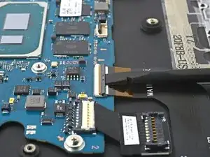
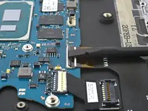
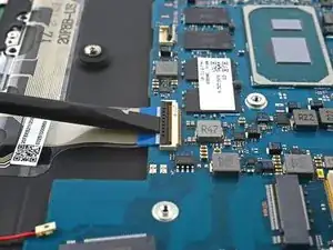
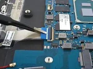
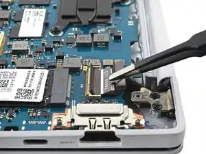
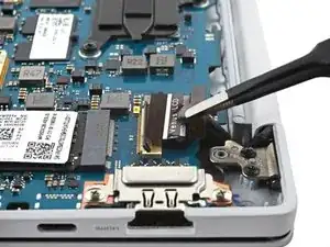
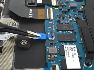
    • Use a spudger to gently pry up the locking flap on the motherboard ZIF connector for the interconnect cable.

    I was wondering please, what kind of connectors are used here? I need to replace the ribbon cable and the locking flap connectors on both the main and sub boards.

    PrintsWojo -

  15. c5dnwAFjG6WGhrng
    c5dnwAFjG6WGhrng
    IfEEbmXCHDmUYpeU
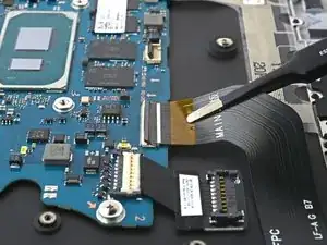
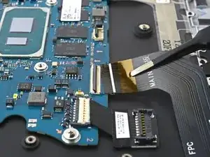
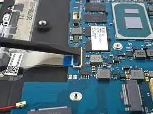
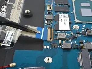
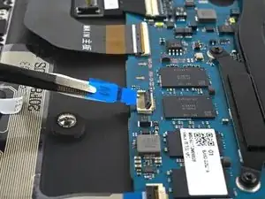
    • Disconnect the interconnect cable by sliding it out from its socket on the motherboard.

  16. ZN6kbVpX1yaAUHmX
    ZN6kbVpX1yaAUHmX
    lZXUGLSXaeLrbWK2
    • Insert a spudger between the frame and the bottom of the battery extender's cable connector.

    • Pry up and disconnect the battery extender's cable connector.

  17. kDHucSWGHeNRchwQ
    kDHucSWGHeNRchwQ
    tIxRvHEjwf5ZDGId
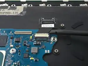
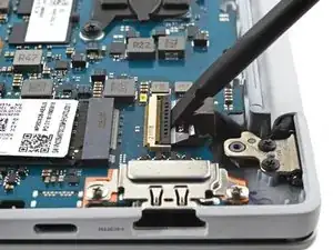
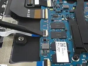
    • Use a spudger to gently pry up the locking flap on the ZIF connector for the keyboard cable.

  18. jKOOJhsguZgZnPxD
    jKOOJhsguZgZnPxD
    pW1SLrojRKSQD3Cj
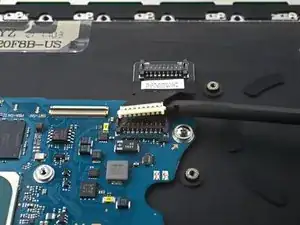
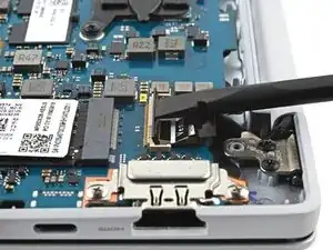
    • Disconnect the keyboard cable by sliding it out from its socket on the motherboard.

  19. wNoit63HmOAfd1Ao
    wNoit63HmOAfd1Ao
    q3dupMGrJryCO3oA
  20. 2OMCIgHEERIBBAFr
    2OMCIgHEERIBBAFr
    5jGF46MKMoouARA5
    • Disconnect the display cable by sliding it out from its socket on the motherboard.

  21. eatOqpvmEt1lrU3L
    eatOqpvmEt1lrU3L
    TYSDa5YA5UY4kUsw
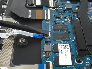
    • Use a spudger to gently pry up the locking flap on the ZIF connector for the touchpad cable.

  22. 5YLbNCwqo3pNhbic
    5YLbNCwqo3pNhbic
    OgUfU1qVVRYUbpTT
    • Disconnect the touchpad cable by sliding it out from its socket on the motherboard.

  23. bitWNijmr2FZJWIA
    bitWNijmr2FZJWIA
    Dn3ffCBDLREnKaVd
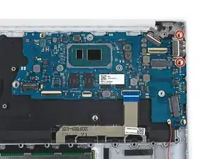
    • Use a Phillips screwdriver to remove the two 3.5 mm-long screws securing the motherboard port bracket.

  24. otfmDGfySQnsuWt5
    otfmDGfySQnsuWt5
    Jj4DTIRyYTJwrU13
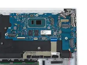
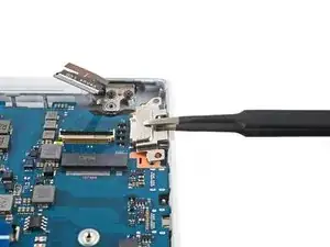
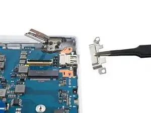
    • Use tweezers, or your fingers, to remove the motherboard port bracket.

  25. oQJfuhKV5vrdhIoV
    oQJfuhKV5vrdhIoV
    JUljkGjVgPPVTXtk
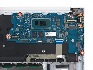
    • Use a Phillips screwdriver to remove the three 3.5 mm-long screws securing the motherboard.

  26. cykcUOSYfaWXKtK6
    cykcUOSYfaWXKtK6
    6HioJSrnpBF1Irst
    Q54TBK3HBZhofL45
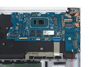
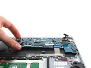
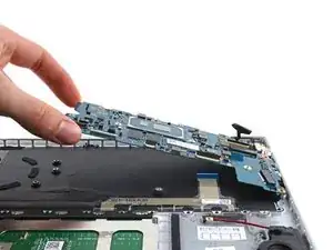
    • Lift the left side of the motherboard upward to separate it from its pegs on the frame.

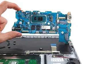
    • Lift the motherboard straight up to separate the rest of the pegs.

    • Remove the motherboard.

    • During reassembly, make sure all of the connectors are above the motherboard before securing it back into the fame.

Conclusion

To reassemble your device, follow the instructions in reverse order and perform the opposite actions, e.g., "reattach" instead of "removing." Skip steps that use heating and prying, and pay close attention to the 📌 bullets as you work through the steps.

Take your e-waste to an R2 or e-Stewards certified recycler.

Repair didn’t go as planned? Check out our Answers community for troubleshooting help.
Alex Diaz-Kokaisl

Member since: 16/01/22

117875 Reputation

0 comments